Secure Care INDOORNODE2 UWB Indoor Node User Manual
Secure Care Products Inc UWB Indoor Node
UserManual.wiki
>
Secure Care
>
INDOORNODE2 User Manual
User Manual
Navigation menu
Upload a User Manual
Namespaces
Wiki Guide
HTML
PDF
Info
Views
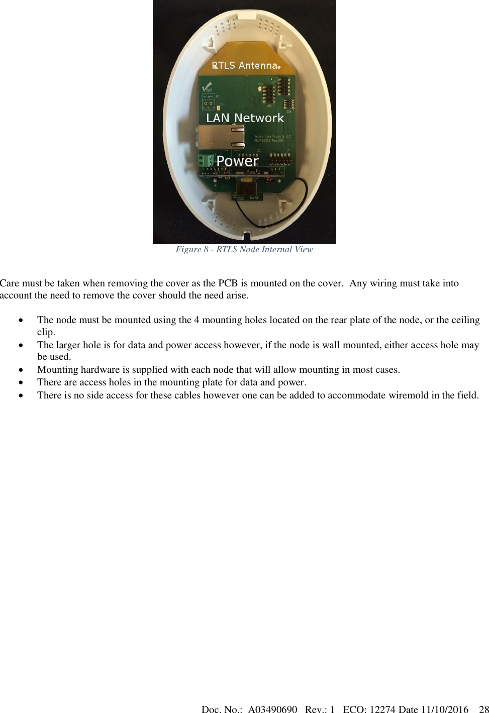
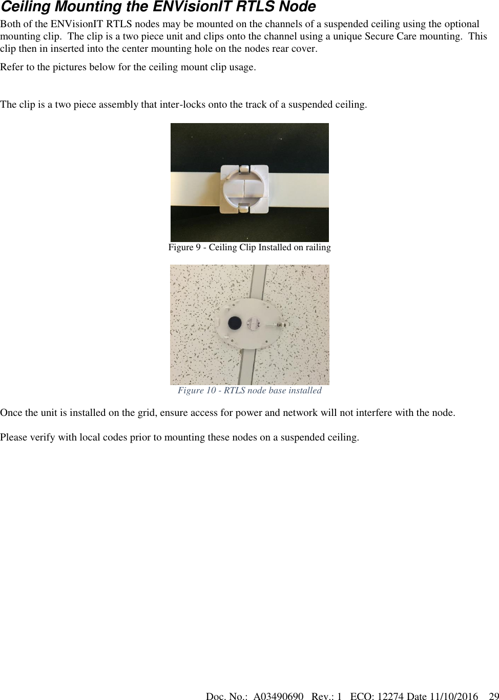
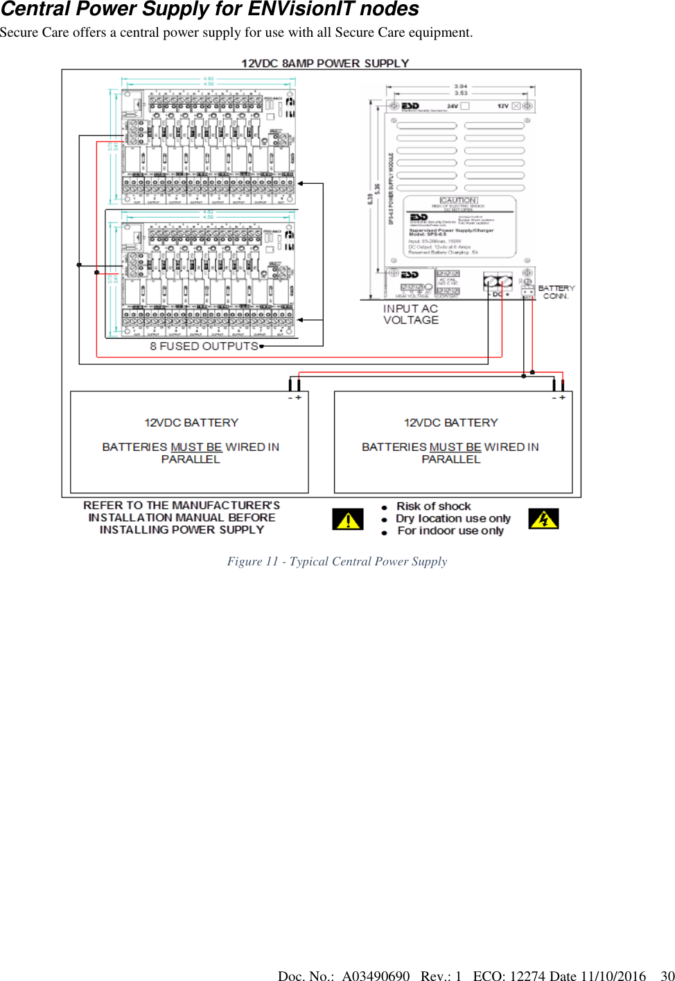
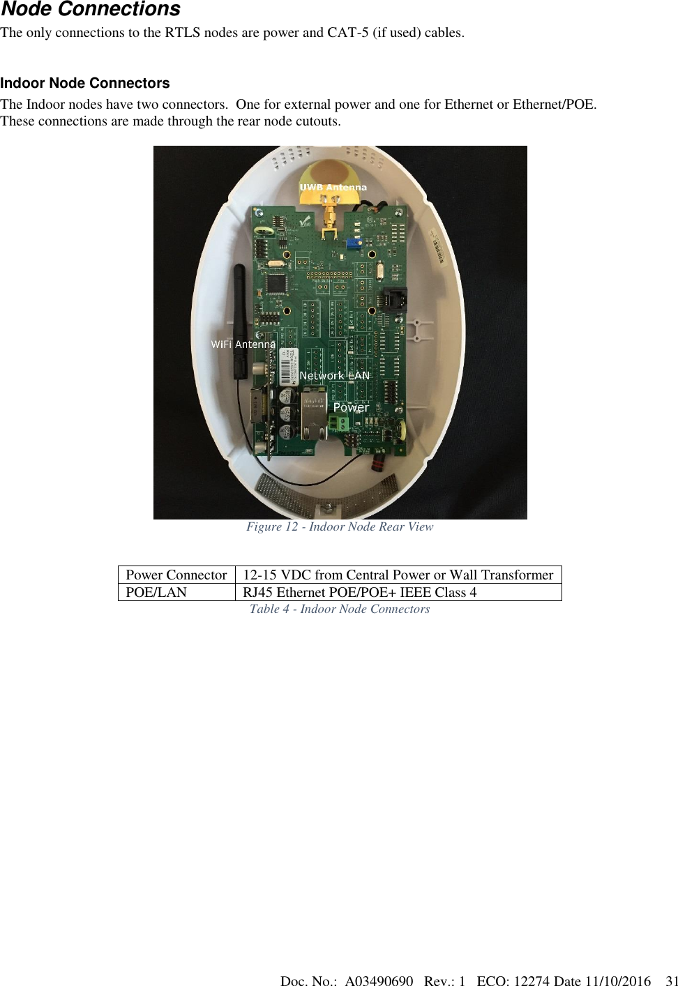
User Manual
Discussion / Help
Navigation