Secure Care INDOORNODE2 UWB Indoor Node User Manual
Secure Care Products Inc UWB Indoor Node
User Manual
Doc. No.: A03490690 Rev.: 1 ECO: 12274 Date 11/04/2016
ENVisionIT RTLS Node Installation Manual
39 Chenell Drive
Concord, NH USA 03301-8501
US Phone: (800) 451-7917 / (603) 223-0745
US Fax: (603) 227-0200
Int’l Phone: +1+603- 223-0745
Int’l Fax: 1-603- 227-0200
www.securecare.com
© 2016 Secure Care Products®, LLC
CONTENT IS SUBJECT TO CHANGE WITHOUT NOTICE
FOR THE LATEST UPDATED MANUALS PLEASE VISIT AND LOG INTO THE DISTRIBUTOR PORTAL
AT
WWW.SECURECARE.COM
Please contact your Distributor /
Installer for service …
Tel.: ___________________________

Doc. No.: A03490690 Rev.: 1 ECO: 12274 Date 11/10/2016 1
TABLE OF CONTENTS
ENVISIONIT RTLS NODE INSTALLATION MANUAL ................................................................................ 0
TABLE OF CONTENTS ............................................................................................................................... 1
TABLE OF FIGURES ................................................................................................................................... 4
SECTION 1 IMPORTANT NOTICES ........................................................................................................ 5
SECTION 2 SYSTEM BLOCK DIAGRAM ............................................................................................... 9
Part Numbers ....................................................................................................................................................... 10
Transmitters ......................................................................................................................................................... 10
SECTION 3 POWER AND GROUNDING REQUIREMENTS ................................................................ 11
General Information .................................................................................................................................................. 11
SECTION 4 TYPICAL INSTALLATION ................................................................................................. 12
Installation Overview ................................................................................................................................................ 12
Determine if the system is Wired or Wireless ......................................................................................................... 12
Wired connection ................................................................................................................................................. 12
Network Structure ................................................................................................................................................ 12
Wireless connection ............................................................................................................................................. 12
Mounting the Nodes ................................................................................................................................................... 12
Locating Node Positions ...................................................................................................................................... 13
Connecting the ENVisionIT RTLS device into the system .................................................................................... 13
SECTION 5 DEVICE SPECIFICATIONS ................................................................................................ 14
ELECTRICAL SPECIFICATIONS ........................................................................................................................ 14
Indoor Node ......................................................................................................................................................... 14
RTLS Node .......................................................................................................................................................... 14
Radio Frequencies ............................................................................................................................................... 14
Wire Specifications .................................................................................................................................................... 14
Power Cable ......................................................................................................................................................... 14
Network Cable ..................................................................................................................................................... 14
Environmental Specifications ................................................................................................................................... 14
Safety ................................................................................................................................................................... 14
Physical Specifications .............................................................................................................................................. 14
Indoor Node Physical Specifications ................................................................................................................... 14
RTLS Node Physical Specifications .................................................................................................................... 15
Doc. No.: A03490690 Rev.: 1 ECO: 12274 Date 11/10/2016 2
RTLS Recognized Badge Types ............................................................................................................................... 16
Location Specific Mounting ................................................................................................................................ 16
Wireless ...................................................................................................................................................................... 17
802.11-a/b/g ......................................................................................................................................................... 17
Ultra-Wideband ................................................................................................................................................... 17
SECTION 6 SYSTEM COMPONENT DESCRIPTIONS ......................................................................... 18
Indoor Node ............................................................................................................................................................... 18
Visual Indicators ........................................................................................................................................................ 19
RTLS Node ................................................................................................................................................................. 19
SECTION 7 STANDARD FEATURES .................................................................................................... 21
Indoor Node ............................................................................................................................................................... 21
Features ................................................................................................................................................................ 21
RTLS Node ................................................................................................................................................................. 21
Features ................................................................................................................................................................ 21
SECTION 8 THEORY OF OPERATION ................................................................................................. 22
Real Time Location System ...................................................................................................................................... 22
Ultra-Wideband ................................................................................................................................................... 22
ENVisionIT RTLS Nodes .................................................................................................................................... 22
Anchor NODE ............................................................................................................................................................ 22
Anchor to Standard node communication............................................................................................................ 22
Anchor Node to Server communication .............................................................................................................. 23
SECTION 9 INSTALLATION AND CONNECTIONS ............................................................................. 24
Pre-Installation Requirements ................................................................................................................................. 24
Basic Installation of Nodes ........................................................................................................................................ 24
Mounting the Indoor Node ....................................................................................................................................... 24
Surface Mount Enclosure for Indoor Node .......................................................................................................... 24
Flush Mount Enclosure for the Indoor Nodes ...................................................................................................... 25
Mounting the RTLS node ......................................................................................................................................... 27
Wall Mounting the RTLS node ........................................................................................................................... 27
Ceiling Mounting the ENVisionIT RTLS Node ...................................................................................................... 29
Central Power Supply for ENVisionIT nodes ......................................................................................................... 30
Node Connections ...................................................................................................................................................... 31
Indoor Node Connectors ...................................................................................................................................... 31
RTLS Node Connectors ....................................................................................................................................... 32
Doc. No.: A03490690 Rev.: 1 ECO: 12274 Date 11/10/2016 3
Configuring devices ................................................................................................................................................... 32
SECTION 10 ADDING DEVICES ......................................................................................................... 33
Secure Care Software ................................................................................................................................................ 33
ENVisionIT RTLS Management Software .......................................................................................................... 33
mVision Event Notification Software .................................................................................................................. 33
Loading the RTLS System with Device Information .............................................................................................. 33
Adding a node to the RTLS network ................................................................................................................... 33
SECTION 11 TESTING ......................................................................................................................... 34
SYSTEM TEST ......................................................................................................................................................... 34
Testing node coverage ......................................................................................................................................... 34
Testing tag coverage ............................................................................................................................................ 34
Testing Location Accuracy .................................................................................................................................. 34
Testing Network Connectivity ............................................................................................................................. 34
SECTION 12 TROUBLESHOOTING .................................................................................................... 35
Troubleshooting Nodes .............................................................................................................................................. 35
Basic troubleshooting steps ....................................................................................................................................... 35
Troubleshooting RTSL Network Issues ................................................................................................................... 36
SECTION 13 MAINTENANCE .............................................................................................................. 37
General Maintenance Procedures ............................................................................................................................ 37
RTLS Node .......................................................................................................................................................... 37
Indoor Node ......................................................................................................................................................... 37
SECTION 14 REPLACEMENT PARTS LIST ....................................................................................... 38
SECTION 15 GENERAL PRODUCT WARRANTY .............................................................................. 39
1. Notices .................................................................................................................................................................... 39
2. Limited Warranty ................................................................................................................................................. 41
3. Limitations of Liability.......................................................................................................................................... 42
4. Governing Law and Arbitration .......................................................................................................................... 43
5. Severability ............................................................................................................................................................. 43
6. Waiver .................................................................................................................................................................... 43
SECTION 16 COMPLIANCE INFORMATION ...................................................................................... 44

Doc. No.: A03490690 Rev.: 1 ECO: 12274 Date 11/10/2016 4
Safety .......................................................................................................................................................................... 44
FCC ............................................................................................................................................................................. 44
RADIO AND TELEVISION INTERFERENCE .................................................................................................... 44
APPENDIX A APPENDIX ...................................................................................................................... 45
TABLE OF FIGURES
Figure 1 - Basic System Diagram .................................................................................................................................. 9
Figure 2 - Indoor Node ................................................................................................................................................ 18
Figure 3 – RTLS Node ................................................................................................................................................ 20
Figure 4 - Surface Mount Rear Cover ......................................................................................................................... 25
Figure 5 - Indoor Node Flush Mount Rear Cover ........................................................................................................ 26
Figure 6 - Flush Mount Enclosure Secure Part Part# 461 ............................................................................................ 26
Figure 7 - RTLS Node back plate ................................................................................................................................ 27
Figure 8 - RTLS Node Internal View .......................................................................................................................... 28
Figure 9 - Ceiling Clip Installed on railing .................................................................................................................. 29
Figure 10 - RTLS node base installed ......................................................................................................................... 29
Figure 11 - Typical Central Power Supply .................................................................................................................. 30
Figure 12 - Indoor Node Rear View ............................................................................................................................ 31
Figure 13 - RTLS Node Rear View ............................................................................................................................. 32
Figure 14 - Add Device Screen ................................................................................................................................... 33
Doc. No.: A03490690 Rev.: 1 ECO: 12274 Date 11/10/2016 5
SECTION 1 IMPORTANT NOTICES
PLEASE READ THIS MANUAL BEFORE BEGINNING
THE INSTALLATION OF A SECURE CARE SYSTEM
This installation manual is provided for reference by purchasers and installers of Secure Care Products, LLC
(“Secure Care’s”) systems. This manual is not intended as a catalog of warnings for the protection of anyone or as a
substitute for obtaining professional training or assistance in the design of a facility’s security procedures and systems,
or in the installation, set-up, testing, support, operation, maintenance, repair or use of Secure Care’s systems. Nothing
in this manual modifies the terms of Secure Care’s General Product Warranty Statement or of any written agreement
signed by Secure Care or creates further warranties or extends benefits of any sort to anyone beyond those already
expressly established in Secure Care’s General Product Warranty Statement and in any written contract signed by
Secure Care.
1. Secure Care is Not Responsible for the Locks
ALL LOCKS USED WITH SECURE CARE’S SYSTEM ARE DESIGNED, MANUFACTURED, LABELED
AND DELIVERED SOLELY BY AN INDEPENDENT VENDOR OVER WHOM SECURE CARE HAS NO
CONTROL AND FOR WHOSE ACTIONS OR FAILURES TO ACT SECURE CARE DISCLAIMS ALL
RESPONSIBILITY. REGARDLESS OF WHETHER THE LOCKS CARRY SECURE CARE’S LOGO OR NAME
OR ANY OTHER TRADEMARK, SERVICE MARK OR TRADE NAME USED OR CLAIMED BY SECURE
CARE, SECURE CARE DISCLAIMS ALL WARRANTIES, EXPRESS OR IMPLIED, WITH RESPECT TO THE
LOCKS AND/OR THEIR USE WITH OR OPERATION IN THE SECURE CARE SYSTEM, INCLUDING,
WITHOUT LIMITATION, ALL IMPLIED WARRANTIES OF MERCHANTABILITY, FITNESS FOR A
PARTICULAR PURPOSE, TITLE AND/OR NON-INFRINGEMENT. SECURE CARE ALSO DISCLAIMS ALL
OBLIGATIONS WITH RESPECT TO THE LOCKS AND/OR THEIR USE WITH OR OPERATION IN THE
SECURE CARE SYSTEM THAT MIGHT OTHERWISE ARISE OR BE IMPLIED FROM THE FACT THAT
SUCH LOCKS CARRY SECURE CARE’S LOGO OR NAME OR ANY OTHER TRADEMARK, SERVICE
MARK OR TRADE NAME USED OR CLAIMED BY SECURE CARE OR FROM THE DELIVERY OR
INSTALLATION OF THE LOCKS WITH SECURE CARE SOFTWARE, PARTS AND/OR PRODUCTS OR
FROM A COURSE OF DEALING OR USAGE IN TRADE. ALL RESPONSIBILITY FOR DESIGNING,
MANUFACTURING, LABELING AND WARNING OF HIDDEN DEFECTS OR DANGERS IN THE LOCKS
AND/OR THEIR USE WITH AND OPERATION IN THE SECURE CARE SYSTEM RESTS EXCLUSIVELY
WITH THE INDEPENDENT VENDOR, AND ANY CLAIMS, COSTS, DAMAGES OR LIABILITIES ARISING
FROM THE LOCKS AND/OR THEIR USE WITH OR OPERATION IN THE SECURE CARE SYSTEM SHALL
BE MADE SOLELY AGAINST THE INDEPENDENT VENDOR.
2. Secure Care Is Not Responsible for The Computer Hardware.

Doc. No.: A03490690 Rev.: 1 ECO: 12274 Date 11/10/2016 6
IF YOU PURCHASE COMPUTER HARDWARE THROUGH SECURE CARE AND REQUEST THAT
SECURE CARE SOFTWARE BE INSTALLED AND TESTED ON THAT HARDWARE AT THE FACTORY,
SECURE CARE WARRANTS ONLY THAT THE HARDWARE AND THE SOFTWARE PACKAGES WERE
INSTALLED, SET-UP AND TESTED PRIOR TO SHIPMENT IN ACCORDANCE WITH ALL SECURE CARE
PRODUCT MANUALS AND THAT, AT THE TIME THE HARDWARE AND THE SOFTWARE PACKAGES
WERE FINALLY INSPECTED AT THE FACTORY, THEY WERE PERFORMING (SUBJECT TO SECURE
CARE’S SPECIFIED TOLERANCES) IN ACCORDANCE WITH SECURE CARE’S SPECIFICATIONS.
SECURE CARE WILL NOT BE RESPONSIBLE FOR ANY DEFECTS IN OR PROBLEMS CAUSED BY THE
HARDWARE, ALL CLAIMS FOR WHICH MUST BE MADE TO THE HARDWARE MANUFACTURER
AND/OR VENDOR. SECURE CARE DISCLAIMS ALL WARRANTIES, EXPRESS OR IMPLIED, WITH
RESPECT TO THE HARDWARE AND/OR ITS USE WITH OR OPERATION IN THE SECURE CARE SYSTEM,
INCLUDING, WITHOUT LIMITATION, ALL IMPLIED WARRANTIES OF MERCHANTABILITY, FITNESS
FOR A PARTICULAR PURPOSE, TITLE AND/OR NON-INFRINGEMENT. SECURE CARE ALSO
DISCLAIMS ALL OBLIGATIONS WITH RESPECT TO THE HARDWARE AND/OR ITS USE WITH OR
OPERATION IN THE SECURE CARE SYSTEM THAT MIGHT OTHERWISE ARISE OR BE IMPLIED FROM
THE FACT THAT SUCH HARDWARE CARRIES SECURE CARE’S LOGO OR NAME OR ANY OTHER
TRADEMARK, SERVICE MARK OR TRADE NAME USED OR CLAIMED BY SECURE CARE OR FROM THE
DELIVERY OR INSTALLATION OF THE HARDWARE WITH SECURE CARE SOFTWARE, PARTS AND/OR
PRODUCTS OR FROM A COURSE OF DEALING OR USAGE IN TRADE. ALL RESPONSIBILITY FOR
DESIGNING, MANUFACTURING, LABELING AND WARNING OF HIDDEN DEFECTS OR DANGERS IN
THE HARDWARE AND/OR ITS USE WITH AND OPERATION IN THE SECURE CARE SYSTEM RESTS
EXCLUSIVELY WITH THE HARDWARE MANUFACTURER AND/OR VENDOR, AND ANY CLAIMS,
COSTS, DAMAGES OR LIABILITIES ARISING FROM THE HARDWARE AND/OR ITS USE WITH OR
OPERATION IN THE SECURE CARE SYSTEM SHALL BE MADE SOLELY AGAINST THE HARDWARE
MANUFACTURER AND/OR VENDOR.
3. Several Factors Outside the Secure Care System Can Affect its Performance
Secure Care’s software, parts and products are designed for operation in a wireless system. However, the range,
performance, and predictability of any wireless system, including Secure Care’s, is dependent on several factors,
including, but not limited to, the following: building structure; environmental extremes (e.g., temperature, earth
tremors, air pollution, etc.); the proximity of other wireless devices; the presence of variable speed products; sources
of Radio Frequency Interference (RFI); physical orientation and positioning of the equipment; and sources of Electro
Static Discharge (ESD). Secure Care is not responsible for the effect of these types of factors on operation of its
software, parts and products and disclaims all responsibility for any claim relative thereto.
4. The Secure Care System Must be Properly Installed
Secure Care's system must be installed, set-up, tested, supported, operated, maintained, repaired and used only in
accordance with all manuals and instructions (including the user, installation, technical and other manuals) issued by
Secure Care (the "Product Manuals"). It is your responsibility to assure that any person who might be installing,
setting-up, testing, supporting, maintaining or repairing the Secure Care system knows the contents of and has access
to the Product Manuals and has successfully completed Secure Care technical training. It is also your responsibility
to assure that any person who might be operating or using this Product knows the contents of and has access to the
Product Manuals and has successfully completed Secure Care in-service training. Secure Care can not be responsible
for performance problems caused by a failure to follow prescribed and appropriate procedures for installation, set-up,
testing, support, operation, maintenance, repair and use.
All adjustable features on new and repaired Secure Care software, parts and products are shipped with “factory
default” settings. These “factory default” settings may not comply with building and life safety codes or other
applicable laws and regulations in the location where they are installed or operated. Secure Care strongly recommends,
therefore, that the settings on all Secure Care software, parts and products be checked and, if necessary, reset to comply
with local building and life safety codes and other applicable laws and regulations at the time of any installation, set-
up, testing, support, maintenance or repair.
5. Performance of the Secure Care System Software Depends on Proper Maintenance

Doc. No.: A03490690 Rev.: 1 ECO: 12274 Date 11/10/2016 7
Secure Care’s system is driven by software. However, the performance and reliability of any software-driven
system depends on adequately maintaining the recommended minimum configuration of computing platform,
operating systems and applications programs and on regularly performing industry-standard and application-specific
backup processes. If recommended minimum configurations of computing platform, operating systems, and
applications programs are not adequately maintained, or if appropriate backups are not regularly performed, the
software may not drive the system as intended. Secure Care is not responsible for operational problems caused by a
failure to perform these maintenance and backup procedures and disclaims all responsibility for any claim relative
thereto.
6. Only a Qualified Service Technician Should Work on a Secure Care System
Secure Care does not authorize, and strongly recommends against, any installation or field replacement of software,
parts or products by untrained contractors or facility staff. Such work can be hazardous, can render the system
ineffective and will void any Secure Care warranty or liability that might otherwise relate to the system.
Before any software, parts or products which have been designed and manufactured by Secure Care can be safely
installed, set-up, tested, supported, maintained or repaired, technical training in accordance with standards established
by Secure Care is required. Regardless of how Secure Care’s software, parts or products are obtained, they should
not be installed, set-up, tested, supported, maintained or repaired by any person who has not satisfactorily completed
that technical training (a “qualified service technician”.) When Secure Care’s software, parts or products are sold
separately from installation services, it is assumed that only a qualified service technician will conduct any installation,
set-up, testing, support, maintenance or repair involving that software, part or products.
7. Only a Authorized Distributor or Installer can Install a Secure Care System
8. Secure Care Products LLC, requires all installations, upgrades or servicing of an existing installation of any
and all SCP products or systems to be performed by factory certified Distributors and/or Installers with
signed distributor or installer agreements. Customers that gain technical service certifications and maintain
their certifications over time are allowed to install replacement hardware and
service previous installations conducted by certified distributors for the facilities they own and operate only
for the products they are certified to and for the sole purpose of maintenance and repairs. In doing
so, they assume liability for those repairs and maintenance. Any individual working for and assisting a
company who has not signed a distributor agreement and as a result is not a certified distributor of Secure
Care Products LLC will assume all liability of the equipment/system in its entirety. Certified individuals
no longer working for a certified Secure Care distributor is no longer considered certified to
install/service Secure Care Product equipment/systems.
9. Equipment/systems installed outside the above criteria will void any and all warranty given by Secure Care
Products, LLC.
10. Any Work Must Comply with Electrical and Life Safety Codes
It is important that any installation, set-up, testing, support, operation, maintenance, repair or use involving the
system comply with all local and national electrical and life safety codes. If you have any questions about compliance
with those codes, please contact your local authorities.
11. Immediately Have Replacements or Repairs Checked On-Site by a Qualified Service Technician

Doc. No.: A03490690 Rev.: 1 ECO: 12274 Date 11/10/2016 8
Secure Care receives and responds to telephone and dial-in inquires (the “Help Line”) about its software, parts and
products for the purpose of discussing users’ experiences with Secure Care’s system, helping users better understand
how their systems work, and providing ideas about what may be causing difficulties. However, Secure Care cannot
accurately diagnose the cause of any problems or give complete instructions on how to fix problems over the telephone
or Internet. The only way to assure that software, parts or products are installed, set-up, tested, supported, maintained
or repaired correctly or that a Secure Care system is functioning properly is to have it examined on site by a qualified
service technician. In addition, Secure Care software, parts and products cannot be operated or used correctly by
anyone who has not successfully completed Secure Care in-service training. Secure Care’s Help Line is not a
substitute for on-site diagnosis and servicing by a qualified service technician or for successful completion of Secure
Care in-service training. Secure Care strongly recommends that any installation, set-up, testing, support, maintenance
or repair of a system that is performed by a person who has not satisfactorily completed technical training in
accordance with standards established by Secure Care be immediately checked on-site by a qualified service
technician.
WARNING: Even slight modifications to the system or changes in the operating environment may cause Secure
Cares system to malfunction. The only way to assure that secure cares system has been installed, SET-UP, TESTED,
SUPPORTED, maintained and repaired correctly is to have a qualified service technician do the work.
12. The Secure Care System is not a Substitute for Careful Identification and Monitoring by Professional Staff
Secure Care’s software, parts and products have been designed to augment a facility’s reasonable procedures for
protecting residents, patients, and infants. However, no system or combination of procedures and equipment can
eliminate all risk or assure complete security. Secure Care’s system is not intended as a substitute for the careful
identification and monitoring of residents, patients, and infants by a facility’s professional staff.
Revised 3/10/16
Doc. No.: A03490690 Rev.: 1 ECO: 12274 Date 11/10/2016 9
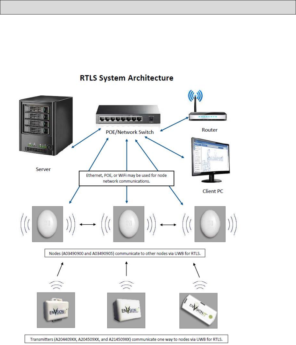
SECTION 2 SYSTEM BLOCK DIAGRAM
The typical RTLS installation will consist of 4 or more nodes placed at strategic locations within a room or area
communicating with one or more primary nodes via a network link. The nodes receive the RTLS tags and badges at
the 4 GHz or 6.5 GHz frequency being transmitted by the tags. Using Real Time Location algorithms in the
ENVisionIT software the system can locate a tag within the perimeter of the node layout.
Figure 1 - Basic System Diagram

Doc. No.: A03490690 Rev.: 1 ECO: 12274 Date 11/10/2016 10
Note that the Client PC, router, POE+ switch and server may be supplied by customer or Secure Care
Products, LLC.
Wireless Nodes are manufactured by Secure Care Products LLC for use in RTLS system. Nodes receive UWB
signals from RTLS transmitters. This information is passed on to computer for processing needed to determine the
location of transmitters. Nodes communicate among local groups for synchronization to aid in the location process.
Nodes receive one way signals from transmitters
Transmitters are manufactured by Secure Care Products LLC for use in RTLS system. The transmitters send UWB
signals to nodes to aid in location. This information is passed on to the computer for processing in determining the
precise location of transmitters.
RTLS system software developed by Secure Care Products LLC ties all this together. The software allows
customers to know the location of staff, patients, and assets in their facility with unprecedented accuracy.
Part Numbers
Kit #
Part Number
Description
A03490900-x
Indoor node, Surface mount UWB channel 2
A03490900-x
Indoor node, flush mount UWB channel 2
A03490905-x
RTLS Node Flush Mount Channel 2
A03490905-x
RTLS Node Flush Mount Channel 5
Table 1 Part Numbers
Transmitters
These are the transmitter families that are supported on the RTLS system. There are currently 4 classes of tags.
These tag types are UWB as well as monitored by existing Secure Care door management products.
RTLS Security A204409xx Tags
RTLS Multi-Vision A204509xx Tags
The following two tag types are UWB only.
RTLS Economy Asset tag (UWB Only) A2145090x
Staff Safety badge (UWB only) A2145091x

Doc. No.: A03490690 Rev.: 1 ECO: 12274 Date 11/10/2016 11
SECTION 3 POWER AND GROUNDING REQUIREMENTS
General Information
Both nodes, can be powered up via Power-Over-Ethernet, an approved central power supply or an approved plugin
power supply powered by a 110/220/230VAC duplex outlet specific to regional or country options (minimum two
amp) within ten cable feet of the intended installation location.
It is strongly recommended to run dedicated and isolated circuit to power nodes and other devices.
NOTICE!
When using a plugin power supply:
Do not extend the power supply cord provided. The maximum distance the duplex outlet should be from a node is
ten cable feet.
Do not connect the node power to a receptacle controlled by a switch.
PLEASE READ SAFETY PRECAUTIONS IN SECTION 4 BEFORE PROCEEDING
NOTICE!
This equipment may only be operated indoors. Operation outdoors is in violation of 47 U.S.C. 301 and could subject
the operator to serious legal penalties.

Doc. No.: A03490690 Rev.: 1 ECO: 12274 Date 11/10/2016 12
SECTION 4 TYPICAL INSTALLATION
WARNING: All life safety and electrical codes must be strictly followed.
Installation Overview
As with any Monitoring System, each application can be different. Use the guidelines below as a basic
understanding of what a standard application would be like.
1. Seek prior approval from local life safety officials prior to installing any locking system.
2. Identify all equipment to be installed and inspect for any damage that may have resulted during shipment. If
damage is found notify the carrier immediately and arrange for inspection. Be sure to retain all shipping and
packaging materials.
3. Install any communication and/or power wires, if necessary from the Node to the appropriate power/data
location. Leave sufficient extra length to allow for node placement adjustments.
4. The location of the Nodes is provided by the system configuration documentation. Mount as required. Standard
application would place this equipment on the wall 5’ to 10’ off the floor.
5. Make all necessary wiring connections as shown in Section 9 of this manual.
6. Plug in all power supplies to un-switched, backed up power sources. Do not connect to a switched receptacle
7. The system is now ready for tuning, programming, and testing
Determine if the system is Wired or Wireless
The method that the nodes will be communicating and how they are to be powered is provided with the system
configuration documentation.
Wired connection
Connect the node to the network port with Cat 5A Ethernet cable for the ENVisionIT network.
If using Power over Ethernet (POE), the switch must meet IEEE Class 4 POE+
If using a central power supply the power cables will need to be run.
Network Structure
The ENvisionIT RTLS network is intended to be an isolated network. Connections to existing infrastructure
networks should be only be done after careful planning.
Wireless connection
The ENVisionIT node can connect wirelessly via 802.11 a/b/g to the Secure Care ENVisionIT network. Once
connected, the node will attempt to automatically join and build the RTLS network. The nodes will communicate
between themselves via UWB and WiFi.
Mounting the Nodes
The nodes can be mounted in several ways.
Flush Wall Mounted
Suspended ceiling mount.
There are mounting holes in the base that allow for wall mounting or there is an option of using ceiling clips to
mount the node to the grid of a dropped ceiling.
Doc. No.: A03490690 Rev.: 1 ECO: 12274 Date 11/10/2016 13
Locating Node Positions
All node locations will be pre-determined and the mounting locations will be provided as part of the installation
specific documentation. It should be noted that the locations specified may have to be adjusted during final testing
to ensure proper coverage and tag detection.
Prior to finalizing the node mounting, it is recommended to temporarily place the node at the specified location
using painter tape. Once the final location is determined, then the node can be permanently mounted.
See Appendix x for an example of the installation location document.
Connecting the ENVisionIT RTLS device into the system
Once the nodes are connected to power and the network, they must be configured into the ENVisionIT configuration
tool.
Refer to the ENVisionIT users guide for detailed steps to add a device into the system.

Doc. No.: A03490690 Rev.: 1 ECO: 12274 Date 11/10/2016 14
SECTION 5 DEVICE SPECIFICATIONS
ELECTRICAL SPECIFICATIONS
Indoor Node
• Input Power: 12 – 15vdc 1A
• POE+ IEEE Class 4
• Wall plug or central power.
• Battery Back Up: None
RTLS Node
• Input Power: 12 – 15vdc 1A
• POE+ IEEE Class 4
• Wall plug or central power
• Battery Back Up: None
Radio Frequencies
• Ultra Wideband at 4 and 6.5 GHz
• WiFi 802.11 a/b/g/n
Wire Specifications
Power Cable
Plenum Shielded Low Power cable: 1 pair 18 AWG, PN C600006300
Network Cable
Cat 5A or Cat 6 Ethernet
Environmental Specifications
Safety
Please pay attention to the following safety warnings: These products should not be used in a manner not specified
by the manufacturer.
• Refer servicing to trained, qualified personnel
• There are no serviceable parts inside the nodes.
• Do not install substitute parts or perform any unauthorized modifications to the node.
• Power supply: Risk of shock
• Dry location use only
• For indoor use only
Physical Specifications
Indoor Node Physical Specifications
Front Cover
ABS
Mounting
Surface Mount, flush mount or ceiling mount
Terminal Connections
Pluggable Terminal Block for central or wall mounted power
RJ45 Ethernet connector
For wired network and POE with Rear Wire Entry
Node Components
Surface Mounted Components, PCB Assembly

Doc. No.: A03490690 Rev.: 1 ECO: 12274 Date 11/10/2016 15
Physical Dimensions:
Oval 61/2”L x 61/2”WxH3”
RTLS Node Physical Specifications
Front Cover
ABS Plastic
Mounting
Surface Mount or dropped ceiling mount
Terminal Connections
Pluggable Terminal Block for central or wall mounted power
RJ45 Ethernet connector
For wired network and POE with Rear Wire Entry
Node Components
Surface Mounted Components, PCB Assembly
Physical Dimensions:
Oval 5 7/8” L x 4” W x 1 ½ “ H
Table 2- Physical Specifications

Doc. No.: A03490690 Rev.: 1 ECO: 12274 Date 11/10/2016 16
RTLS Recognized Badge Types
The nodes recognize the following types of badges and tags
Economy Asset Tag
A21450906-23 (Ch 2)
A21450906-53 (Ch 5)
Provides tracking of valuable assets through out a
monitored and includes a programmable button.
RTLS Security Tag
A20440930-2 (Ch 2)
A20440930-5 (Ch 5)
Provides UWB location information and has a
programmable status push button. Has door management
capability
RTLS Multi-Vision Tag
A20450930-2 (Ch 2)
A20450930-5 (Ch 5)
Provides UWB location information and has a
programmable status push button and has door
management capabilities. It also has cutband capability.
Staff Safety Badge
A21450910-21 (Ch 2)
A21450910-51 (Ch 5)
Provides UWB location information and has a
programmable push button.
Table 3 - RTLS Tags
Location Specific Mounting
Any location specific mounting data will be added when known. The typical Node locations are pre-determined and
a location map will be provided to the installer.
General process will generally consist of a pre-site visit by a Secure Care trained distributor to take an initial facility
scan to determine node placement.
If the system is a wireless system, a Wi-Fi scan is done as well.
Once node placement is determined, power wiring is calculated along with the number of power supplies. Then the
installation team will be provided with the node locations and power requirements and begin planning and preparing
for node install.
Any Exit panels, EXIU and/or KinderGUARD devices will be installed at this time as well. The EXIU and/or
EHUB should be connected to the Secure Care system router for the ENVisionIT network.
During this time the PC will be set up and ENVisionIT software installed at the factory. All available node specific
information will be factory loaded into the system.
Once nodes are in place, the ENVisionIT software will be configured with the device information for the facility.
When all devices are configured into the system, a system wide test will be performed to determine accuracy and
coverage.
Doc. No.: A03490690 Rev.: 1 ECO: 12274 Date 11/10/2016 17
Wireless
802.11-a/b/g
The nodes, when connecting wirelessly to a network, use a secure wireless network that confirms to 802.11a/b/g/n.
Ultra-Wideband
The Secure Care RTLS system uses the ultra-wideband frequencies of 4 and 6.5 GHz and are set to use either
channel 2 or channel 5 depending on the country. The tags transmit a signal that is received by the node and, in
conjunction with the time of flight data from other nodes, the tag is located.
Doc. No.: A03490690 Rev.: 1 ECO: 12274 Date 11/10/2016 18
SECTION 6 SYSTEM COMPONENT DESCRIPTIONS
There are two types of RTLS nodes.
An Indoor node
A smaller, RTLS node
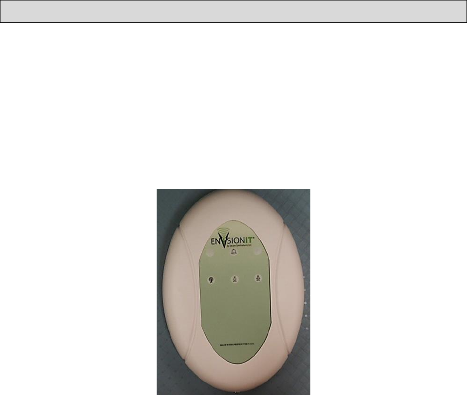
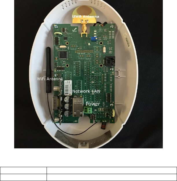
Indoor Node
The Indoor Node is a self-contained multi-function RTLS tag locator node that is contained in a plastic housing,
The node is typically installed on a wall along with 3 others to locate tags within their specific area.
The nodes are used in conjunction with a primary node in each location. The primary node then communicates tag
information back to the ENVisionIT software via wired or wireless Ethernet.
Figure 2 - Indoor Node
The RTLS Indoor Node recognizes ultra-wideband signals sent from Secure Care Products ultra-wideband devices,
The Indoor Node routes received information to the appropriate locations via:
• Wi-Fi to and from the network and nodes
• Local Area Network (LAN).
• UWB from tags
The Indoor Node will operate normally when receiving signals from as many as 4000 tags or when low levels of RF
noise are present.
The Indoor Node can be used with the following devices:
• Other Nodes
• RTLS Security Tags
• RTLS Multi-Vision Tags
• RTLS Staff Safety Badges
• RTLS Economy Asset Tags
The Indoor Node connects to Secure Care ENVisionIT Software via:
Doc. No.: A03490690 Rev.: 1 ECO: 12274 Date 11/10/2016 19
• A hard wired LAN connection between an off-the-shelf switch and the server.
• A Wi-Fi (802.11 a/b/g/n) network
• Ethernet LAN and Wireless (Wi-Fi).
The SCP Wi-Fi (802.11 a/b/g/n) network may be configured to join any existing 802.11 a/b/g/n network. However,
this type of network should not be promoted. Rather a standalone secure 802.11 a/b/g/n network should be promoted
to ensure adequate security and reliability.
The Indoor Node can be used with a central power supply, POE, or wall brick.
All user programmable features of the Indoor node can be managed remotely via the ENVisionIT system.
The Indoor Node can be connected to remotely via an internet connection (GoToAssist) (Requires a connection to
an external Internet from the ENVisionIT server)
Visual Indicators
Visual indicators for power and connectivity:
• Power LED (Green/Red
• Green = On and connected to the network
• Red = On, but not connected to the network
The Indoor Node will relay RTLS information to the Secure Care ENVisionIT software application.
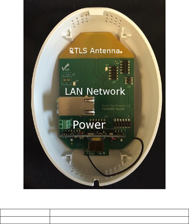
RTLS Node
The Node is a self-contained tag locator node contained in a plastic housing which mounts on the wall or suspended
ceiling.
The node is installed along with at least 3 other Nodes to locate tags within their specific area.
The Nodes are used in conjunction with a primary node in each location. The primary node then communicates tag
information back to the ENVisionIT software via wired or wireless Ethernet.
The Node is available as either UWB Channel 2 or UWB Channel 5. This is country specific.
The Node recognizes ultra-wideband signals sent from Secure Care Products ultra-wideband devices. The Node
routes received information to the appropriate locations via:
• Other Nodes
• RTLS Security Tags
• RTLS Multi-Vision Tags
• RTLS Staff Safety Badges
• RTLS Economy Asset Tags

Doc. No.: A03490690 Rev.: 1 ECO: 12274 Date 11/10/2016 20
Figure 3 – RTLS Node
The Nodes communicates with the ENVisionIT Software via:
• A hard wired LAN connection between an off-the-shelf switch/router (wireless or wired) and the
server. Note that the system is designed to be an isolated stand-alone network.
• A secure Wi-Fi (802.11 a/b/g/n) network
The SCP RTLS Wi-Fi network may be configured to join any existing 802.11 a/b/g/n network however, this type of
network will not be promoted. Rather a secure, standalone 802.11 a/b/g/n network should be promoted to ensure
adequate security and reliability.
The Node can be powered by a central 12VDC power supply, POE+ (Power over Ethernet), or wall brick.
All user programmable features are done remotely via the network connection to the ENVisionIT system.
An authorized person at Nurse Station can some change features of a node via the ENVisionIT software.
The ENVisionIT Node can be directly accessed remotely via an internet connection (External Internet Connection to
the ENVisionIT server is required.)
There is a green LED backlit through the plastic in the logo area when the node is powered on.

Doc. No.: A03490690 Rev.: 1 ECO: 12274 Date 11/10/2016 21
SECTION 7 STANDARD FEATURES
Indoor Node
Features
Wired or Wireless connectivity to the Secure Care ENVisionIT Network.
Accurate location of tags
Software managed
Larger version of the RTLS node
RTLS Node
Features
Small compact size
Can be powered via POE or external power source
Has wired and wireless communications
Manageable remotely via ENVisionIT software
The Node does not track or KinderGUARD transmitters. However it can be programmed such that if certain tags
enter certain zones, an alert or alarm can be generated and the appropriate response sent to designated staff.

Doc. No.: A03490690 Rev.: 1 ECO: 12274 Date 11/10/2016 22
SECTION 8 THEORY OF OPERATION
Real Time Location System
There are several types of Real Time Location System (RTLS) technologies. The ENVisionIT system can
determine a tag location by the data each node sends to the system.
The Secure Care ENVisionIT RTLS system uses a minimum of 4 node transceivers to locate a tag. The receivers
communicate with a primary node for synchronization and management.
Each node is located in a very precise location within the monitored area. Using this information along with the
time difference the signal arrived at each node (TDOA), the ENVisionIT system plots the tag location.
The nodes can use WiFi or LAN for communications between nodes and the ENVisionIT server.
Ultra-Wideband
Ultra-wideband (UWB) is a radio technology that uses a very low energy level for short-range, high-bandwidth
communications over a large portion of the radio spectrum. This system operates in the 4GHz and 6GHz spectrum.
Depending on the country, the ENVisionIt system will either be configured for UWB band 2 or UWB band 5. Most
installations in the U.S. will use UWB band 5. UWB band 2 is used in Canada, Australia, and New Zealand and
other countries in Europe.
ENVisionIT RTLS Nodes
The ENVisionIT nodes are microprocessor-based units that recognizes UWB signals sent from Secure Care
Products RTLS Tags. Communication between nodes is via Wi-Fi or wired network switch and the Windows server
running Secure Care ENVisionIT software.
The nodes are categorized into either an ANCHOR node or a standard node.
Every node must either be an anchor node or have at least one anchor node associated with it.
The standard node communicates with the anchor node for synchronization and control. Each node will send the tag
information it is detecting along with the position information to the server.
The anchor nodes then passes that information on to the ENVisionIT system. Once the ENVisionIT system has
received the information from the nodes, it can calculate the tag position and report it on the GUI.
Communications between the nodes and RTLS tags is over UWB communications. Tag recognition is via MAC
address, the last 4 octets of which are decoded as the TAG ID.
Anchor nodes use MAC addresses to talk to standard nodes. All nodes use their assigned IP address to
communicate to the ENVisionIT system.
Anchor NODE
Anchor to Standard node communication
The master node is responsible for the synchronizing of the nodes it is master for with the rest of the ENVisionIT
system. This synchronizing of nodes is critical to correct operation of the system.
It also manages the data from each node, and relaying that data on to the ENVisionIT system.
The nodes will auto-establish a network with other nodes upon power up. They will continually look for other
nodes and will begin receiving data from them once they are configured into the ENVisionIT systems Device
Configuration.
Doc. No.: A03490690 Rev.: 1 ECO: 12274 Date 11/10/2016 23
The Anchor node is determined during the configuration of the RTLS network and is assigned during the device
configuration stage of the system setup.
Anchor Node to Server communication
The Primary node communicates with the Secure Care ENVisionIT software installed on a Windows server 2012.
The communication is via Cat 5 or wireless 802.11a/b/g/n secure wireless network.

Doc. No.: A03490690 Rev.: 1 ECO: 12274 Date 11/10/2016 24
SECTION 9 INSTALLATION AND CONNECTIONS
Pre-Installation Requirements
Prior to installing the ENVisionIT RTLS system, insure all material and installation information is at hand.
The basic steps for installing are:
Locate the placement location map provided with the system.
Identify and mark the each node location as specified in the site map.
Locate and install power and network components.
Route cables to each location as necessary.
Install the ENVisionIT server and connect it to the RTLS network router. The server will have been pre-
configured with the node information at the factory.
The ‘X’ and ‘Y’ location information in the map is the exact node location, in meters, from a given point in the
room. The ‘Z’ is the height of the node off the floor.
Each node has its own unique ID assigned in the ENVisionIT server. This ID is associated with where that node
should be located in the room. It is critical that each node is placed correctly according to the map.
The placement map is the finished product of the site scan performed at the time of sale. This map shows the close
approximate location of each Node, Wi-Fi antennas, Wi-Fi routers and switch(es) and power supplies.
Basic Installation of Nodes
Mounting options available for the nodes are wall mounted using the mounting holes provided or mounted on a
suspended ceiling grid.
The location of each node is critical and is pre-determined from previous site scans and provided by Secure Care.
The wall mounted nodes are always flush mounted and must not be mounted over a metal wall box.
When installing the node, pay close attention to the coordinates that are provided as this affects the node tracking
accuracy.
Exact final placement will be determined during system testing but should be within a few centimeters of the
designated location.
The final system testing involves verifying tag location accuracy, tag coverage, node communication and
synchronization. The entire process can be very extensive depending on the size of the system and any relocation
issues that may arise during system testing.
Mounting the Indoor Node
The Indoor Node can be mounted using one of three methods. Surface, flush or ceiling mount.
Surface Mount Enclosure for Indoor Node
The surface mount enclosure is designed to be flush mounted on the wall. It mounts using the screws, anchors, and
strain relief provided with the enclosure. Wiring may be routed through one or more of the three provided knockout
locations or through surface mounted non-metallic conduit into the knockouts on the top of the enclosure.
After routing wires appropriately to the enclosure location, use the enclosure as a template to mark and drill for the
four anchor locations.
Doc. No.: A03490690 Rev.: 1 ECO: 12274 Date 11/10/2016 25
Drill a ¼” hole for each anchor location and install plastic anchors provided if needed.
Apply strain relief connectors to the required knockout locations. Route wires through the strain relief connector.
Tighten strain relief connector around the wires. Wires should withstand a pull of 35 pounds without slipping
through connector. Use the screws provided to mount enclosure to wall.
Figure 4 - Surface Mount Rear Cover
NOTE: Strain relief of routed cables is required to retain UL product listing. If above instructions are not followed,
the product UL listing is subject to removal.
Flush Mount Enclosure for the Indoor Nodes
Using the Indoor node flush mount rear mounting plate, the RTLS Indoor node can be mounted to our current
mounting box.
The flush mount enclosure is designed to be mounted in the wall where the node will be installed. It mounts using a
standard 3 gang box and strain relief provided with the enclosure.
Wiring may be routed through one or more of the four provided knockout locations on the back, sides, or top of the
wall enclosure.
Cable access and
Ceiling mount
Doc. No.: A03490690 Rev.: 1 ECO: 12274 Date 11/10/2016 26
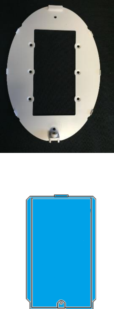
Figure 5 - Indoor Node Flush Mount Rear Cover
A typical Flush mount wall box as provided by Secure Care.
Figure 6 - Flush Mount Enclosure Secure Part Part# 461
After routing wires to the enclosure location, use the enclosure as a template to mark and cut the wallboard for
inserting the enclosure. Apply strain relief connector to required knockout locations. Route wires through strain
relief connector. Tighten strain relief connector around the wires. Wires should withstand a pull of 35 pounds
without slipping through the connector. Insert the enclosure into the wall.
Doc. No.: A03490690 Rev.: 1 ECO: 12274 Date 11/10/2016 27
Cable access and
Ceiling mount
Mounting the RTLS node
Wall Mounting the RTLS node
Route power and/or network cables to each node location leaving adequate extra cable length for node re-location
adjustments.
Using the location information provided for each node in the system, temporarily mount the node using painters
tape.
• Connect each node to power and network and attach it the location specified.
• If the system is wireless, configure the wireless router and ensure it sees each node.
• If the system is wired LAN, verify each node is seen at the router.
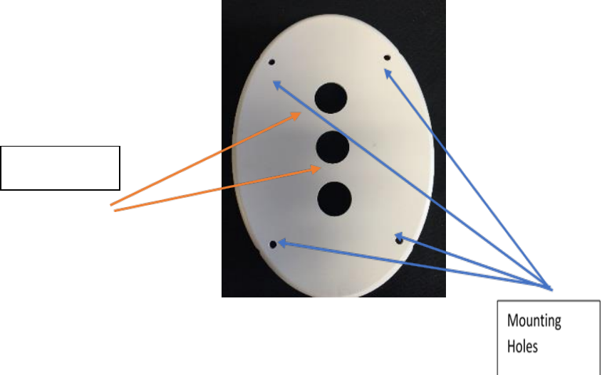
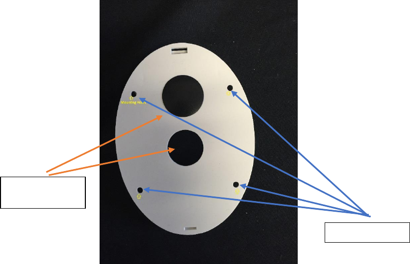
Figure 7 - RTLS Node back plate
Mounting Holes
Doc. No.: A03490690 Rev.: 1 ECO: 12274 Date 11/10/2016 28
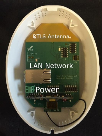
Figure 8 - RTLS Node Internal View
Care must be taken when removing the cover as the PCB is mounted on the cover. Any wiring must take into
account the need to remove the cover should the need arise.
The node must be mounted using the 4 mounting holes located on the rear plate of the node, or the ceiling
clip.
The larger hole is for data and power access however, if the node is wall mounted, either access hole may
be used.
Mounting hardware is supplied with each node that will allow mounting in most cases.
There are access holes in the mounting plate for data and power.
There is no side access for these cables however one can be added to accommodate wiremold in the field.
Doc. No.: A03490690 Rev.: 1 ECO: 12274 Date 11/10/2016 29
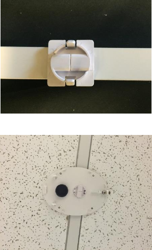
Ceiling Mounting the ENVisionIT RTLS Node
Both of the ENVisionIT RTLS nodes may be mounted on the channels of a suspended ceiling using the optional
mounting clip. The clip is a two piece unit and clips onto the channel using a unique Secure Care mounting. This
clip then in inserted into the center mounting hole on the nodes rear cover.
Refer to the pictures below for the ceiling mount clip usage.
The clip is a two piece assembly that inter-locks onto the track of a suspended ceiling.
Figure 9 - Ceiling Clip Installed on railing
Figure 10 - RTLS node base installed
Once the unit is installed on the grid, ensure access for power and network will not interfere with the node.
Please verify with local codes prior to mounting these nodes on a suspended ceiling.
Doc. No.: A03490690 Rev.: 1 ECO: 12274 Date 11/10/2016 30
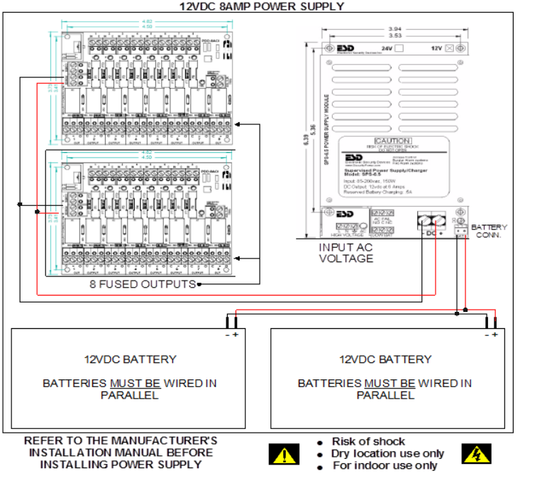
Central Power Supply for ENVisionIT nodes
Secure Care offers a central power supply for use with all Secure Care equipment.
Figure 11 - Typical Central Power Supply
Doc. No.: A03490690 Rev.: 1 ECO: 12274 Date 11/10/2016 31
Node Connections
The only connections to the RTLS nodes are power and CAT-5 (if used) cables.
Indoor Node Connectors
The Indoor nodes have two connectors. One for external power and one for Ethernet or Ethernet/POE.
These connections are made through the rear node cutouts.
Figure 12 - Indoor Node Rear View
Power Connector
12-15 VDC from Central Power or Wall Transformer
POE/LAN
RJ45 Ethernet POE/POE+ IEEE Class 4
Table 4 - Indoor Node Connectors
Doc. No.: A03490690 Rev.: 1 ECO: 12274 Date 11/10/2016 32
RTLS Node Connectors
Figure 13 - RTLS Node Rear View
Power Connector
12-15 VDC from Central Power or Wall Transformer
POE/LAN
RJ45 Ethernet POE/POE+ IEEE Class 4
Table 5 RTLS Node Connections
When using a wired network connection be careful when plugging in the Ethernet cable. The fit is tight.
Configuring devices
Once all devices are mounted and wired, they must be configured into the ENVisionIT system.
Doc. No.: A03490690 Rev.: 1 ECO: 12274 Date 11/10/2016 33
SECTION 10 ADDING DEVICES
Secure Care Software
All programming for the Node is performed through the Secure Care ENVisionIT software. Refer to the
ENVisionIT Technical User manual for programming and user information.
ENVisionIT RTLS Management Software
All tags and nodes can be tracked and managed using the Secure Care ENVisionIT software.
mVision Event Notification Software
The ENVisionIT system can interface with the Secure Care mVision alerting software. Events will then be sent to
the assigned staff.
Loading the RTLS System with Device Information
Adding a node to the RTLS network
Follow these steps to add a device into the ENVisionIT system. Devices include MatchMaker, EXIU, EHUB,
nodes, tags, network routers, etc.
Devices can only be added after the ENVisionIT system has been installed and configured.
Refer to the ENVisionIT system user manual for more specific information and steps.
From the Secure Care dashboard
1. Choose the “Menu” tab
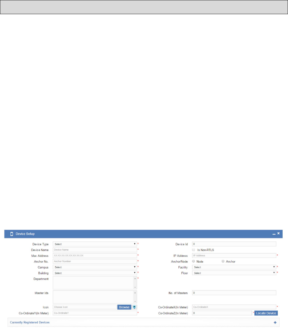
2. Choose the Device Setup tab
3. Enter the device information in the fields provided
4. Save device info (Button at bottom right of screen)
Figure 14 - Add Device Screen
The Device Configuration screen will change depending on the device being added.

Doc. No.: A03490690 Rev.: 1 ECO: 12274 Date 11/10/2016 34
SECTION 11 TESTING
SYSTEM TEST
This section will provide the test procedures that will help ensure the ENVisionIT system is working correctly and
the steps necessary to repair any failing components of the system.
Testing node coverage
Using a test tag, go to at least 5 locations within the monitored area and verify the location is reported correctly on
the ENVisionIT system.
Testing tag coverage
Using the test tag, monitor the tracking of the tag as it is moving around the area being monitored verifying the tag is
seen in all locations and there are no dead spots. Dead spots may develop after installing the system as equipment
and furniture get moved blocking or reducing coverage.
Testing Location Accuracy
Verify tags and devices are correctly displayed with the correct location on the system.
Testing Network Connectivity
Normal network troubleshooting and testing should be used.
Ping devices
Network logs
Cable tester
Wireless test tools

Doc. No.: A03490690 Rev.: 1 ECO: 12274 Date 11/10/2016 35
SECTION 12 TROUBLESHOOTING
Troubleshooting the RTLS system requires a full understanding of the RTLS system.
Types of problems that may be encountered are:
Node Failure
Network Failure
Tag Failure
Server/PC failure
Outside interference with the WiFi
Change in the area being monitored resulting in dead spots
Troubleshooting Nodes
Once we understand how to determine the failing node this section will be written.
The EHUB Talk tool can be used to communicate with the Nodes. Nodes can also be accessed via the network. See
xxx below for the commands and data that can be obtained.
Basic troubleshooting steps
Symptom 1: LED’s on the ENVisionIT Indoor node are off
Potential causes and corrective actions:
Power switch on the RTLS ENVisionIT node is in the OFF position.
Improper output voltage: Verify output voltage is approximately 12VDC.
Verify that the power supply is connected and has an output of 12VDC.
The problem may be the ENVisionIT node. Replace the RTLS ENVisionIT node.
Symptom 2: The node will not reset when the code is entered
Potential causes and corrective actions:
Incorrect reset code is being entered into the keypad.
Check for bent pins on the Remote Keypad if used.
Initialize node programming and try the default reset codes.
The problem may be in the node. Replace the node.
Symptom 3: The node has no range with tag(s) present.
Potential causes and corrective actions:

Doc. No.: A03490690 Rev.: 1 ECO: 12274 Date 11/10/2016 36
Verify that the tag in use is not expired or damaged.
Verify that the same tag is seen by other nodes in the system. If a tag is seen by other nodes at the
expected range, the node may be defective.
Verify that the node is not damaged.
The problem may be in the RTLS ENVisionIT Mini node. Replace the node making sure to
change the device information in the ENVisonIT system.
Symptom 4 The Node is not communicating with the Primary Node
Potential causes and corrective actions
Verify the node has power
If the node is wireless, verify the wireless router sees the node and is connected.
If the node is wired, verify the router can see the node
Troubleshooting RTSL Network Issues
Verify IP address and gateway settings for the RTLS network. The RTLS network should be private and secure.
Check network connectivity to the switch/router using ping and other network troubleshooting tools.
Check system event logs, ENVisionIT service event logs and SQL/MySQL event logs for clues.

Doc. No.: A03490690 Rev.: 1 ECO: 12274 Date 11/10/2016 37
SECTION 13 MAINTENANCE
General Maintenance Procedures
This section will contain any maintenance procedures that need to be performed on the RTLS system. Generally a
regularly scheduled check of power and voltage levels, tag coverage and Computer updating and regular PM should
be all the maintenance necessary. If a node is defective, the system will detect it. Defective nodes and other
components should be returned via the Secure Care RMA process.
RTLS Node
Maintenance for the RTLS node consists of verifying the operation and there is no physical damage.
There are no user serviceable parts in the RTLS node
Indoor Node
Maintenance for the Indoor node consists of verifying operation and inspecting for physical damage,
There are no user serviceable parts in the Indoor node

Doc. No.: A03490690 Rev.: 1 ECO: 12274 Date 11/10/2016 38
SECTION 14 REPLACEMENT PARTS LIST
Part
Description
A03490900-x
Indoor Node
A03490905-x
RTLS Node
P03490230
Ceiling Clip
461
Plastic Flush Mount Kit
Table 6 - RTLS Parts List

Doc. No.: A03490690 Rev.: 1 ECO: 12274 Date 11/10/2016 39
SECTION 15 GENERAL PRODUCT WARRANTY
SECURE CARE PRODUCTS, LLC
GENERAL PRODUCT WARRANTY STATEMENT
BY PERMITTING INSTALLATION OR BY MAKING USE OF ANY PRODUCT OR SERVICE DESIGNED OR
MANUFACTURED BY SECURE CARE PRODUCTS, LLC (“SECURE CARE”) (INCLUDING SUPPORT
SERVICES, MAINTAINED SOFTWARE AND MAJOR RELEASES, WHETHER OR NOT IT IS COVERED BY
ANY SOFTWARE MAINTENANCE OR LICENSE AGREEMENT) (“THIS PRODUCT”), YOU
ACKNOWLEDGE THAT YOU HAVE READ ALL THE TERMS AND CONDITIONS OF THIS GENERAL
PRODUCT WARRANTY STATEMENT, THAT YOU UNDERSTAND THEM, AND THAT YOU AGREE TO BE
BOUND BY THEM. YOU UNDERSTAND THAT, IF YOU PURCHASED THIS PRODUCT FROM ANY
AUTHORIZED DISTRIBUTOR OF SECURE CARE, THAT DISTRIBUTOR IS NOT SECURE CARE’S AGENT
AND IS NOT AUTHORIZED TO MAKE ANY REPRESENTATIONS OR WARRANTIES OR TO AGREE TO
ANY TERMS OR CONDITIONS WHICH ARE DIFFERENT FROM ANYTHING EXPRESSLY SET FORTH IN
THIS GENERAL PRODUCT WARRANTY STATEMENT.
If you do not agree to the terms and conditions of this General Product Warranty Statement, do not permit the
installation or make use of this Product and promptly return this Product to the place where you obtained it for a full
refund. If you have any difficulty obtaining a refund, please contact Secure Care at the telephone number provided in
Section 2.B below.
1. Notices
A. ALL LOCKS USED WITH THE SECURE CARE SYSTEM ARE DESIGNED, MANUFACTURED,
LABELED AND DELIVERED SOLELY BY AN INDEPENDENT VENDOR OVER WHOM SECURE CARE
HAS NO CONTROL AND FOR WHOSE ACTIONS OR FAILURES TO ACT SECURE CARE DISCLAIMS ALL
RESPONSIBILITY. REGARDLESS OF WHETHER THE LOCKS CARRY SECURE CARE’S LOGO OR NAME
OR ANY OTHER TRADEMARK, SERVICE MARK OR TRADE NAME USED OR CLAIMED BY SECURE
CARE, SECURE CARE DISCLAIMS ALL WARRANTIES, EXPRESS OR IMPLIED, WITH RESPECT TO THE
LOCKS AND/OR THEIR USE WITH OR OPERATION IN THE SECURE CARE SYSTEM, INCLUDING,
WITHOUT LIMITATION, ALL IMPLIED WARRANTIES OF MERCHANTABILITY, FITNESS FOR A
PARTICULAR PURPOSE, TITLE AND/OR NON-INFRINGEMENT. SECURE CARE ALSO DISCLAIMS ALL
OBLIGATIONS WITH RESPECT TO THE LOCKS AND/OR THEIR USE WITH OR OPERATION IN THE
SECURE CARE SYSTEM THAT MIGHT OTHERWISE ARISE OR BE IMPLIED FROM THE FACT THAT
SUCH LOCKS CARRY SECURE CARE’S LOGO OR NAME OR ANY OTHER TRADEMARK, SERVICE
MARK OR TRADE NAME USED OR CLAIMED BY SECURE CARE OR FROM THE DELIVERY OR
INSTALLATION OF THE LOCKS WITH SECURE CARE SOFTWARE, PARTS AND/OR PRODUCTS OR
FROM A COURSE OF DEALING OR USAGE IN TRADE. ALL RESPONSIBILITY FOR DESIGNING,
MANUFACTURING, LABELING AND WARNING OF HIDDEN DEFECTS OR DANGERS IN THE LOCKS
AND/OR THEIR USE WITH AND OPERATION IN THE SECURE CARE SYSTEM RESTS EXCLUSIVELY
WITH THE INDEPENDENT VENDOR, AND ANY CLAIMS, COSTS, DAMAGES OR LIABILITIES ARISING
FROM THE LOCKS AND/OR THEIR USE WITH OR OPERATION IN THE SECURE CARE SYSTEM SHALL
BE MADE SOLELY AGAINST THE INDEPENDENT VENDOR.
Doc. No.: A03490690 Rev.: 1 ECO: 12274 Date 11/10/2016 40
B. IF YOU PURCHASE COMPUTER HARDWARE THROUGH SECURE CARE AND REQUEST THAT
SECURE CARE SOFTWARE BE INSTALLED AND TESTED ON THAT HARDWARE AT THE FACTORY,
SECURE CARE WARRANTS ONLY THAT THE HARDWARE AND THE SOFTWARE PACKAGES WERE
INSTALLED, SET-UP AND TESTED PRIOR TO SHIPMENT IN ACCORDANCE WITH ALL SECURE CARE
PRODUCT MANUALS AND THAT, AT THE TIME THE HARDWARE AND THE SOFTWARE PACKAGES
WERE FINALLY INSPECTED AT THE FACTORY, THEY WERE PERFORMING (SUBJECT TO SECURE
CARE’S SPECIFIED TOLERANCES) IN ACCORDANCE WITH SECURE CARE’S SPECIFICATIONS.
SECURE CARE WILL NOT BE RESPONSIBLE FOR ANY DEFECTS IN OR PROBLEMS CAUSED BY THE
HARDWARE, ALL CLAIMS FOR WHICH MUST BE MADE TO THE HARDWARE MANUFACTURER
AND/OR VENDOR. SECURE CARE DISCLAIMS ALL WARRANTIES, EXPRESS OR IMPLIED, WITH
RESPECT TO THE HARDWARE AND/OR ITS USE WITH OR OPERATION IN THE SECURE CARE SYSTEM,
INCLUDING, WITHOUT LIMITATION, ALL IMPLIED WARRANTIES OF MERCHANTABILITY, FITNESS
FOR A PARTICULAR PURPOSE, TITLE AND/OR NON-INFRINGEMENT. SECURE CARE ALSO
DISCLAIMS ALL OBLIGATIONS WITH RESPECT TO THE HARDWARE AND/OR ITS USE WITH OR
OPERATION IN THE SECURE CARE SYSTEM THAT MIGHT OTHERWISE ARISE OR BE IMPLIED FROM
THE FACT THAT SUCH HARDWARE CARRIES SECURE CARE’S LOGO OR NAME OR ANY OTHER
TRADEMARK, SERVICE MARK OR TRADE NAME USED OR CLAIMED BY SECURE CARE OR FROM THE
DELIVERY OR INSTALLATION OF THE HARDWARE WITH SECURE CARE SOFTWARE, PARTS AND/OR
PRODUCTS OR FROM A COURSE OF DEALING OR USAGE IN TRADE. ALL RESPONSIBILITY FOR
DESIGNING, MANUFACTURING, LABELING AND WARNING OF HIDDEN DEFECTS OR DANGERS IN
THE HARDWARE AND/OR ITS USE WITH AND OPERATION IN THE SECURE CARE SYSTEM RESTS
EXCLUSIVELY WITH THE HARDWARE MANUFACTURER AND/OR VENDOR, AND ANY CLAIMS,
COSTS, DAMAGES OR LIABILITIES ARISING FROM THE HARDWARE AND/OR ITS USE WITH OR
OPERATION IN THE SECURE CARE SYSTEM SHALL BE MADE SOLELY AGAINST THE HARDWARE
MANUFACTURER AND/OR VENDOR.
C. Secure Care’s software, parts and products are designed for operation in a wireless system. However, the range,
performance, and predictability of any wireless system, including Secure Care’s, is dependent on several factors,
including, but not limited to, the following: building structure; environmental extremes (e.g., temperature, earth
tremors, air pollution, etc.); the proximity of other wireless devices; the presence of variable speed products; sources
of Radio Frequency Interference (RFI); physical orientation and positioning of the equipment; and sources of Electro
Static Discharge (“ESD”). Secure Care cannot be responsible for the effect of these types of factors on operation of
its software, parts and products.
D. This Product must be installed, set-up, tested, supported, operated, maintained, repaired and used only in
accordance with all manuals and instructions (including the user, installation, technical and other manuals) issued by
Secure Care (the “Product Manuals”). It is your responsibility to assure that any person who might be installing,
setting-up, testing, supporting, maintaining or repairing this Product knows the contents of and has access to the
Product Manuals and has successfully completed Secure Care technical training. It is also your responsibility to assure
that any person who might be operating or using this Product knows the contents of and has access to the Product
Manuals and has successfully completed Secure Care in-service training. If you do not have the Product Manuals or
if you have any questions regarding this Product and/or its installation, set-up, testing, support, operation,
maintenance, repair or use, please call Secure Care at the telephone number provided in section 2.B below. Secure
Care cannot be responsible for performance problems caused by a failure to follow published and appropriate
procedures for installation, set-up, testing, support, operation, maintenance, repair and use.
All adjustable features on new and repaired Secure Care software, parts and products are shipped with “factory
default” settings. These “factory default” settings may not comply with building and life safety codes or other
applicable laws and regulations in the location where they are installed or operated. Secure Care strongly recommends,
therefore, that the settings on all Secure Care software, parts and products be checked and, if necessary, reset to comply
with local building and life safety codes and other applicable laws and regulations at the time of any installation, set-
up, testing, support, maintenance or repair.
E. Secure Care’s system is driven by software. However, the performance and reliability of any software-driven
system depends on adequately maintaining the recommended minimum configuration of computing platform,
operating systems and applications programs and on regularly performing industry-standard and application-specific
backup processes. If recommended minimum configurations of computing platform, operating systems, and
applications programs are not adequately maintained, or if appropriate backups are not regularly performed, the
software may not drive the system as intended. Secure Care cannot be responsible for operational problems caused
by a failure to perform these maintenance and backup procedures.
Doc. No.: A03490690 Rev.: 1 ECO: 12274 Date 11/10/2016 41
F. Secure Care does not authorize, and strongly recommends against, any installation or field replacement of
software, parts or products by untrained contractors or facility staff. Such work can be hazardous, can render the
system ineffective and will void any Secure Care warranty or liability that might otherwise relate to the system.
Before any software, parts or products, which have been designed and manufactured by Secure Care can be safely
installed, set-up, tested, supported, maintained or repaired, technical training in accordance with standards established
by Secure Care is required. Regardless of how Secure Care’s software, parts or products are obtained, they should
not be installed, set-up, tested, supported, maintained or repaired by any person who has not satisfactorily completed
that technical training (a “qualified service technician”.) When Secure Care’s software, parts or products are sold
separately from installation services, it is assumed that only a qualified service technician will conduct any installation,
set-up, testing, support, maintenance or repair involving that software, part or products.
G. It is important that any installation, set-up, testing, support, operation, maintenance, repair or use involving
the system comply with all local and national electrical and life safety codes. If you have any questions about
compliance with those codes, please contact your local authorities.
H. Secure Care receives and responds to telephone and dial-in inquires (the “Help Line”) about its software, parts
and products for the purpose of discussing users’ experiences with Secure Care’s system, helping users better
understand how their systems work, and providing ideas about what may be causing difficulties. However, Secure
Care cannot accurately diagnose the cause of any problems or give complete instructions on how to fix problems over
the telephone or Internet. The only way to assure that software, parts or products are installed, set-up, tested,
supported, maintained or repaired correctly or that a Secure Care system is functioning properly is to have it examined
on site by a qualified service technician. In addition, Secure Care software, parts and products cannot be operated or
used correctly by anyone who has not successfully completed Secure Care in-service training. Secure Care’s Help
Line is not a substitute for on-site diagnosis and servicing by a qualified service technician or for successful completion
of Secure Care in-service training. Secure Care strongly recommends that any installation, set-up, testing, support,
replacement, maintenance or repair of a system that is performed by a person who has not satisfactorily completed
technical training in accordance with standards established by Secure Care be immediately checked on-site by a person
who has completed that technical training.
WARNING: EVEN SLIGHT MODIFICATIONS TO THE SYSTEM OR CHANGES IN THE OPERATING
ENVIRONMENT MAY CAUSE SECURE CARE’S SYSTEM TO MALFUNCTION. THE ONLY WAY TO
ASSURE THAT SECURE CARE’S SYSTEM HAS BEEN INSTALLED, SET-UP, TESTED, SUPPORTED,
MAINTAINED, AND REPAIRED CORRECTLY IS TO HAVE A QUALIFIED SERVICE TECHNICIAN DO THE
WORK.
I. Secure Care’s software, parts and products have been designed to augment a facility’s reasonable procedures
for protecting residents, patients, and infants. However, no system or combination of procedures and equipment can
eliminate all risk or assure complete security. Secure Care’s system is not intended as a substitute for the careful
identification and monitoring of residents, patients, and infants by a facility’s professional staff.
2. Limited Warranty
A. Subject to the limitations set forth in this general product warranty statement (as amended from time to time
by Secure Care in its absolute discretion), and unless a different period is specified in writing by Secure Care for a
particular product or service, Secure Care warrants that this product (subject to Secure Care's specified tolerances and
excluding any expendable items), if sold by Secure Care to an authorized Secure Care distributor, shall conform to
the specifications which accompany this product for a period of one (1) year from the date of delivery of this product
by Secure Care to a common carrier, f.o.b. Secure Care’s manufacturing facility in Concord, New Hampshire or, in
the case of services, from the date of first provision of such services. This warranty does not extend to and is not for
the benefit of any person other than an authorized Secure Care distributor who purchases this product from Secure
Care, any sub-distributor thereof and/or the customer to whom this product is first provided for use, by Secure Care,
an authorized Secure Care distributor or any sub-distributor thereof. In the event that this product does not comply
with this warranty, Secure Care will, at its option, either repair or replace this product or refund the purchase price,
provided that this product is returned as provided in section 2.b below. Replacement of this product under warranty
will not extend the original warranty period.
Secure Care will also, at its option, either repair or replace this Product after the warranty has expired, for an additional
charge, provided that this Product is returned as provided in Section 2.B below. If Secure Care repairs or replaces this
Product after the warranty has expired, the terms of the warranty set forth in this Section 2.A for a new Product will
apply to the repaired or replaced Product, with the exception that the term will run for ninety (90) days from the date
of repair or replacement.
Doc. No.: A03490690 Rev.: 1 ECO: 12274 Date 11/10/2016 42
Repair may include the replacement of parts and products with functionally equivalent, reconditioned parts or
products. Any part or product replaced by Secure Care will become the property of Secure Care upon replacement.
B. Warranty service is available by contacting Secure Care at 800-451-7917 and obtaining a Return Authorization
Number. No Product may be returned to Secure Care without first obtaining a Return Authorization Number. When
this Product is returned to Secure Care, please include the Return Authorization Number and a detailed written
description of the problem. Issuance of a Return Authorization Number by Secure Care will not constitute an
admission that there is a problem with the Product being returned, that any problem is covered by warranty or that
Secure Care has any responsibility to repair, replace, make refunds for or pay claims, costs, damages or liabilities
connected with the Product being returned.
NOTE: Transmitters are not repaired, nor is the warranty extended, beyond the expiration date.
If this Product is returned to Secure Care for any reason, you will retain title (unless and until a part or product is
replaced, in which case you will obtain title to the replacement part or product at the time of replacement), the risk of
loss, and the obligation to pay all costs of shipping, storage and other charges and obligations relating to this Product.
C. Except as stated in this section 2, Secure Care disclaims all warranties, express or implied, with respect to the
whole or any part of this product, including, without limitation, all implied warranties of merchantability, fitness for
a particular purpose, title and/or non-infringement. Secure Care also disclaims all obligations that might otherwise
arise or be implied from a course of dealing or usage in trade.
3. Limitations of Liability
A. Regardless of the form of any claim or action, Secure Care’s total liability to all persons, whether singly or
together, for all occurrences combined, for claims, costs, damages or liabilities based on any cause whatsoever and
arising from or in connection with this product, or the manufacture, distribution, promotion, sale, installation, set-up,
testing, support, maintenance, operation, servicing, use or performance of this product, or from or in connection with
any delay or failure in providing this product, shall not exceed the aggregate price (without interest) paid to Secure
Care for this product.
B. In no event shall Secure Care be liable to anyone for any loss of data, loss of profits or loss of use of this product
or any equipment, or for any special, incidental, consequential, exemplary, punitive, multiple, or other damages,
arising from or in connection with the manufacture, distribution, promotion, sale, installation, set-up, testing, support,
maintenance, operation, servicing, use or performance of this product or from or in connection with any delay or
failure in providing or delivering this product.
C. In no event shall Secure Care be liable to anyone for any claims, costs, damages or liabilities caused by: (i)
any distributor’s failure to perform its obligations and responsibilities under a distributor agreement with Secure Care;
(ii) improper or defective promotion, distribution, sale, installation, set-up, testing, support, maintenance or repair of
this product, including work performed, without Secure Care’s prior written consent in its absolute discretion, by a
person who has not satisfactorily completed Secure Care technical training, or in a manner not consistent with Secure
Care technical training; (iii) improper or defective operation or use of this product by a person who has not successfully
completed Secure Care in-service training, or in a manner not consistent with Secure Care in-service training; (iv)
supply of this product by a distributor for use in, or the use of this product in, any system or configuration not designed
to Secure Care standards or in which a distributor or any third party has substituted materials and/or goods not specified
by Secure Care; or (v) deterioration of this product during storage.
D. You agree to indemnify and hold Secure Care harmless from all claims, costs, damages and liabilities asserted
by anyone for any damages that are excluded and waived, or are intended to be excluded and waived, by this section
3, or which are imposed by law on behalf of anyone but which are not expressly stated in this general product warranty
statement.
E. The exclusions, waivers and limitations on claims, costs, damages and liabilities and any rights of
indemnification set forth in this Section 3 shall be enforceable to the maximum extent allowed by law and shall not
be expanded or negated in any respect by Secure Care’s operation of a “help line” to receive and respond to telephone
or dial-in inquires about this product, by any communications through that “help line” or by any actions taken by
anyone following communications with Secure Care over such “help line.”
Doc. No.: A03490690 Rev.: 1 ECO: 12274 Date 11/10/2016 43
4. Governing Law and Arbitration
A. This General Product Warranty Statement, and all questions arising out of or relating to it, shall be governed
by and construed in accordance with the laws of the State of New Hampshire, without giving effect to the conflict of
laws provisions thereof, and excluding the United Nations Convention on contracts for the international sale of goods,
the 1974 convention on the limitation period on the international sale of goods (the “1974 convention”), and the
protocol amending the 1974 convention, done at Vienna April 11, 1980.
B. Any dispute, controversy or claim arising out of or relating to this general product warranty statement shall be
resolved by arbitration. Regardless of the amount in dispute, the arbitration shall be conducted by a single arbitrator
selected by the parties or, if they cannot agree, by a single arbitrator selected in accordance with the commercial
arbitration rules of the American Arbitration Association without regard to the amount in dispute. The arbitration
shall be conducted in English, in accordance with the commercial arbitration rules of the American Arbitration
Association, in Concord, New Hampshire. The decision of the arbitrator shall be binding and enforceable by any state
or federal court in New Hampshire, and you hereby consent to the personal jurisdiction of any state or federal court
in New Hampshire for that purpose. The expense of the arbitration (excluding each side’s own attorneys' fees, costs,
and related expenses) shall initially be paid in equal shares by each side, but the total of such expenses plus any award
of attorneys' fees, cost and expenses shall finally be paid by the parties as the arbitrator determines. Nothing in this
section 4.b shall preclude Secure Care from seeking provisional or equitable relief from any appropriate court to
protect its rights prior to, pending or in the absence of such arbitration proceedings.
5. Severability
The invalidity or unenforceability of any provision of this General Product Warranty Statement shall not affect the
validity or enforceability of any other provision hereof.
6. Waiver
No term or condition of this General Product Warranty Statement may be waived except in writing signed by Secure
Care. A waiver on one or more occasions of any term or condition of this General Product Warranty Statement shall
not constitute or be deemed to be a waiver of such term or condition on any other occasion. No delay or failure of
Secure Care to exercise any right or remedy under this General Product Warranty Statement will operate as a waiver
thereof; no failure to enforce or insist upon compliance with any provision of this General Product Warranty Statement
on any one occasion shall be deemed to be a waiver of Secure Care's right to do so on another occasion; and no course
of dealing will constitute a waiver, alteration, limitation or expansion of any of the parties' rights and obligations under
this General Product Warranty Statement.
Revised 01/22/14

Doc. No.: A03490690 Rev.: 1 ECO: 12274 Date 11/10/2016 44
SECTION 16 COMPLIANCE INFORMATION
Safety
This product meets UL xxxz
FCC
‘‘This equipment may only be operated indoors. Operation outdoors is in violation of 47
U.S.C. 301 and could subject the operator to serious legal penalties.’’
RADIO AND TELEVISION INTERFERENCE
NOTE: This equipment has been tested and found to comply with the limits for a Class A digital device, pursuant to
Part 15 of the FCC rules. These limits are designed to provide reasonable protection against harmful interference
when the equipment is operated in a commercial environment. This equipment generates, uses and can radiate radio
frequency energy and, if not installed and used in accordance with the instruction manual, may cause harmful
interference to radio communications. Operation of this equipment in a residential area is likely to cause harmful
interference in which case the user will be required to correct the interference at his own expense.

Doc. No.: A03490690 Rev.: 1 ECO: 12274 Date 11/10/2016 45
APPENDIX A APPENDIX
Appendix information will be added as needed