Secure Wireless 433TF Wireless Temp/Flood Detector User Manual
Secure Wireless, Inc Wireless Temp/Flood Detector
User Manual

AT&T Model SW-ATT-TF, Temperature/Flood Sensor
Description
The AT&T model number SW-ATT-TF Sensor is a fully supervised, tamper
protected sensor that will monitor ambient temperature detect a flood/no flood
condition. It reports these conditions to the Digital Life Controller. The sensor
can be configured to detect temperature only
Flood Conditions—once the sensor detects the presence of water, the integral
transmitter will send a flood alarm transmission to the Digital Life Controller.
The sensor will also send a restore (no flood) report when the presence of
water is no longer detected by the flood sensor. For flood reporting the sensor
requires the installation of the supplied external flood probe.
Temperature Conditions—the temperature sensor will check the ambient
temperature approximately once per minute. If the temperature has changed
by three (3) degrees F or more since the sensor’s last 3 degree report, the
integral transmitter will send a temperature report to the Digital Life Controller.
(Check the installation section for required wiring for the sensor if it is used in
temperature only configuration.) The temperature sensor does not send a
restore message, but does send ambient temperature approximately once
every 70 minutes as part of the supervisory transmission.
Low Battery—if the battery voltage falls below a prescribed voltage level, the
integral transmitter will a low battery report to the Digital Life Controller
whenever transmitting. (See the ―Changing the Battery‖ section of these
instructions for information about changing the battery.)
Flood Probe Fault- if at any time the sensor detects that the wiring between
the sensor and the flood probe is either open circuit (wire cut or missing) or
short circuit (e.g. installation staple cutting into wires), the sensor will transmit
―sensor trouble‖ multiple times or until the fault is corrected.
Installing the Battery
When the system indicates the sensor battery is low, replace it immediately.
Use the recommended replacement batteries (See specification) or contact
AT&T technical support for more information.
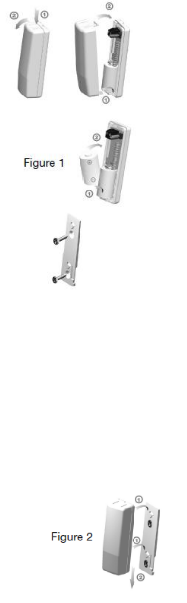
To install the battery, do the following:
1. Carefully remove the top cover from the base by
pressing on the end release button (see Figure 1)
and then remove the cover.
2. Remove the depleted battery and dispose of the
battery as required by local laws. (Disregard this step
for new system installation.)
3. Insert the replacement battery with the + sign facing
towards the middle of the sensor. (The side with the
spring is the – side of the battery.)
4. Replace the top cover.
5. Verify programming and RF communication with the
Digital Life Controller.
Locating the Sensor
1. You can mount the SW-ATT-SW on a wall or ceiling within the
protected area for temperature only, sensor can only be mounted 4 foot
or less from the probe when used for flood detection. Care should be
taken not to locate the sensor near air ducts as the effect of the airflow
from the duct affect the temperature reading.
2. Avoid mounting the sensor in areas with a large quantity of metal or
electrical wiring.
Mounting the Sensor
The SW-ATT-TF is supplied with a mounting plate and accessory
hardware. While the sensor can be mounted directly to a surface,
it is recommended that the mounting plate be used for ease of
removal for servicing.
1. Use the device mounting plate as a template for locating
the mounting holes and mark the locations with a pencil
(See Figure 2).
2. Drill the holes for the screws
3. Secure the mounting plate with the screws provided.
4. Secure the sensor to the mounting plate by carefully guiding the sensor
over the mounting plate. The sensor will snap into place when it is
secured into place (See Figure 2)
Sensor Set-up
For Temperature Only Operation
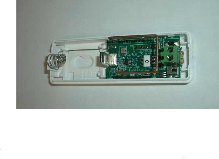
1. Install the supplied 2.2 Megaohm resistor between the Flood Probe
screw terminals on the sensor circuit board. (See Figure 3)
2. The sensor is configured for Temperature only operation.
FIGURE 3
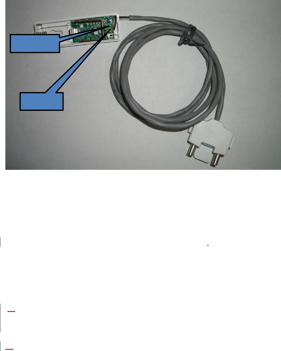
For Temperature/Flood Operation
The flood probe is supplied with a four-foot wire. Connect the flood probe to
the screw terminals located on the sensor circuit board. Observe the polarity of
the wires shown in Figure 4.
FIGURE 4
For Flood Only Operation
The sensor is designed to automatically detect the ambient temperature of the
area where it is located. For flood only applications, the Digital Life Controller
will require programming to ignore the temperature reports.
The flood probe is supplied with a four-foot wire lead. Connect the flood probe
wires to the screw terminals located on the sensor circuit board. Observe
polarity, Black wire connects to the terminal next to the tamper switch.
Locating the Flood Probe
Find a low spot on the floor of the area to be protected. Choose a location
where the probe will not be disturbed by foot traffic and cleaning equipment.
.....
Mounting the Flood Probe
....
Mount the probe with the screws provided. The best installation is where the
plastic center foot is touching the floor which sets the correct probe height.
Enrolling the Transmitter
WHITE WIRE
BLACK WIRE
(Per AT&T requirements)
Verifying the programming and RF communications
(Per AT&T requirements)
Case Tamper Detection
Removing the cover of the SW-ATT-TF will cause the integral transmitter to
send a case tamper report to the Digital Life Controller. This tamper condition
will remain on the system until the case cover is reinstalled and the integral
transmitter sends a tamper restore to the Digital Life Controller.
IMPORTANT INFORMATION ABOUT RADIO DEVICES
1. AT&T radio controls provide a reliable communications link and fill an important
need in portable wireless signaling. However, there are some limitations which
must be observed.
2. For US installations only: the radios are required to comply with FCC rules and
regulations including FCC part 15 devices. As such, they have limited transmitter
power and therefore limited range.
3. A receiver cannot respond to more than one transmitted signal at a time and may
be blocked by radio signals that occur on or near their operating frequencies
regardless of code settings.
4. Changes or modifications to the device may void FCC compliance
5. Infrequently used radio links should be tested regularly to protect against
undetected interference or fault.
6. RF signals can be affected by metal objects including metal doors or large
mirrors. Care should be taken to avoid these objects during installation as they
can interfere with proper operation.
FCC compliance statement
This device complies with FCC Rules and Regulations as Part 15 devices as well as
Industry Canada Rules and Regulations. Operation is subject to the following two
conditions:
1. This device may not cause harmful interference.
2. This device must accept any interference received, including interference that
may cause undesired operation.
Conformité Réglementaire
Ce dispositif est conforme à la réglementation de la IC et (Partie 15) de la
FCC. Son fonctionnement est soumis à deux conditions : (1) ce dispositif

ne doit pas causer d’interférences nuisibles, et (2) ce dispositif doit
accepter toute interférence reçue, y compris les interférences pouvant
entraîner des conditions de fonctionnement indésirables.
WARNING: The battery may explode if mistreated. Do not discharge,
disassemble or dispose of in fire.
Notice to users in California—CR Coin Cell Lithium Battery information:
This product contains a CR Coin Cell Lithium Battery which contains
Perchlorate Material—special handling may apply See
www.dtsc.ca.gov.harardouswaste/perchlorate.
General Specifications
Operating Temperature: 32° to 120° F (0° to 49° C)
Operating Rel. Humidity: 5 to 95%, non-condensing
Operating Frequency: 433.92 MHz
Battery Type: CR 2 3-volt lithium battery
Installation Kit: Double-faced mounting tape, two (4) #6 flat head
woodscrews