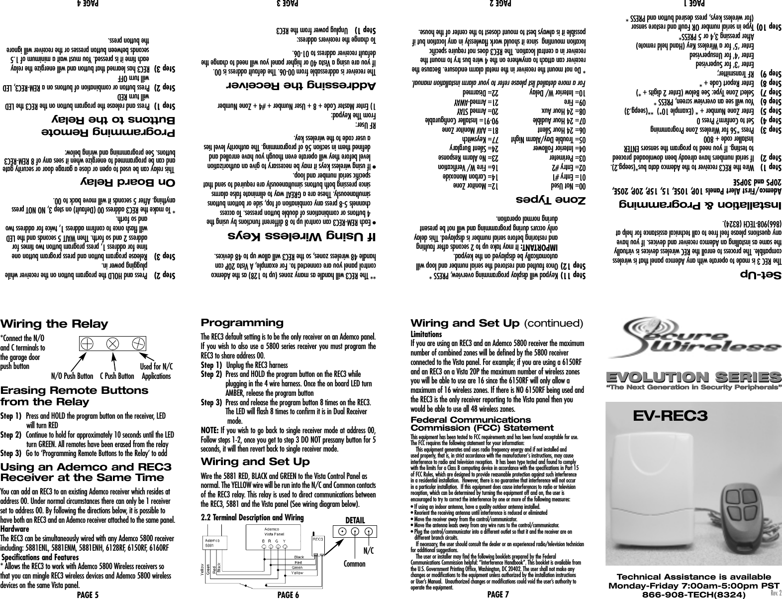
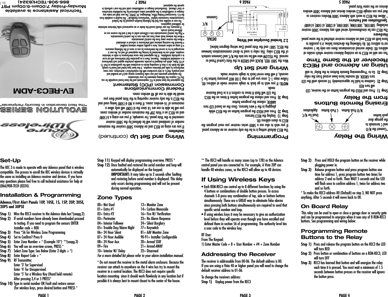
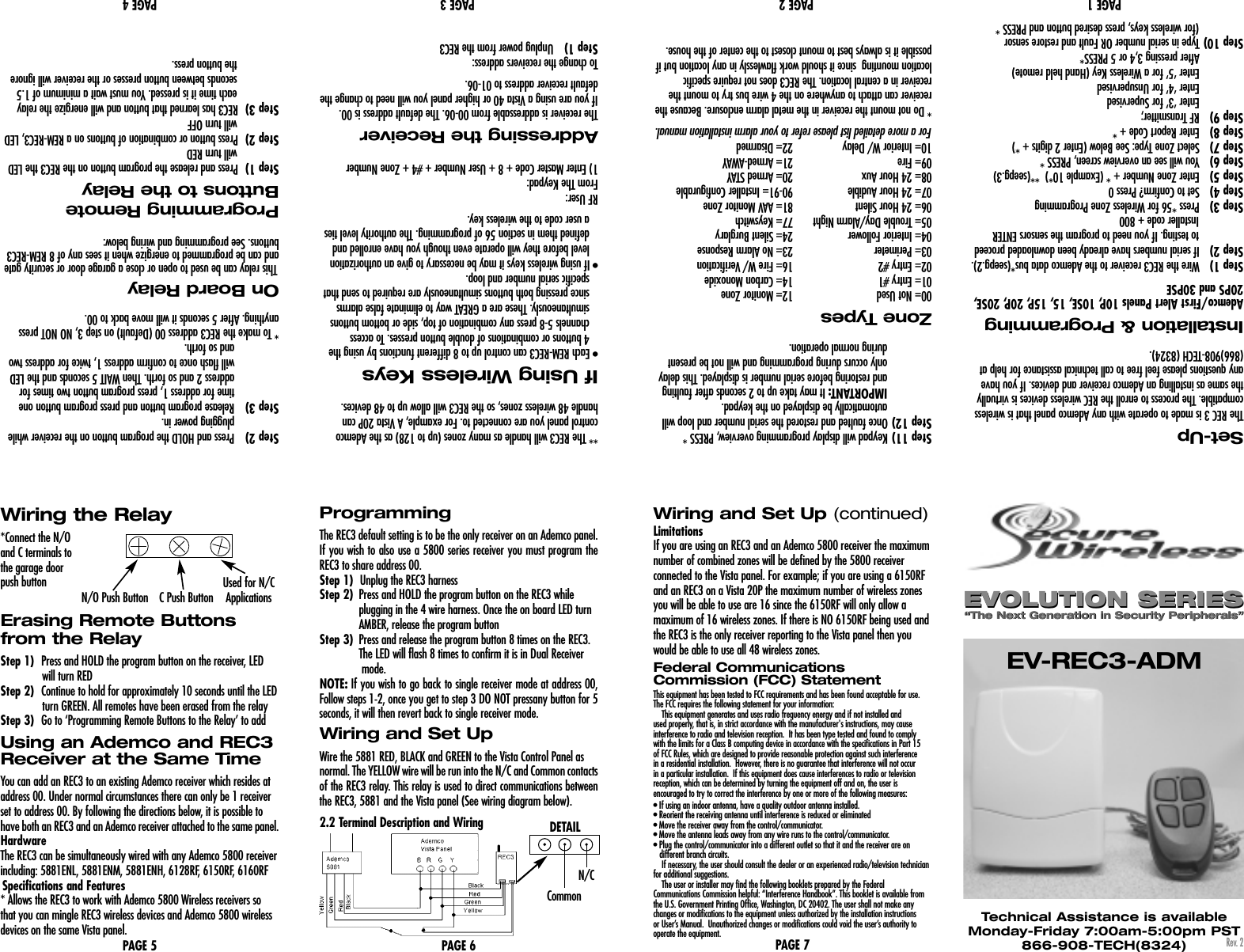
Secure Wireless EVREC3 Wireless Home Security Interface User Manual 7133 SW EV REC3 v2 Manual2

Secure Wireless, Inc Wireless Home Security Interface 7133 SW EV REC3 v2 Manual2

User Manual

Wiring the Relay*Connect the N/O and C terminals to the garage door push buttonErasing Remote Buttonsfrom the RelayStep 1) Press and HOLD the program button on the receiver, LEDwill turn REDStep 2) Continue to hold for approximately 10 seconds until the LEDturn GREEN. All remotes have been erased from the relayStep 3) Go to ‘Programming Remote Buttons to the Relay’ to addUsing an Ademco and REC3Receiver at the Same TimeYou can add an REC3 to an existing Ademco receiver which resides ataddress 00. Under normal circumstances there can only be 1 receiverset to address 00. By following the directions below, it is possible to have both an REC3 and an Ademco receiver attached to the same panel.HardwareThe REC3 can be simultaneously wired with any Ademco 5800 receiverincluding: 5881ENL, 5881ENM, 5881ENH, 6128RF, 6150RF, 6160RFSpecifications and Features* Allows the REC3 to work with Ademco 5800 Wireless receivers sothat you can mingle REC3 wireless devices and Ademco 5800 wirelessdevices on the same Vista panel.PAGE 5EV-REC3EVOLUTION SERIES“The Next Generation in Security Peripherals”“The Next Generation in Security Peripherals”EVOLUTION SERIESTechnical Assistance is availableMonday-Friday 7:00am-5:00pm PST866-908-TECH(8324)PAGE 1 PAGE 2 PAGE 3 PAGE 4Rev. 2Used for N/CN/O Push Button C Push Button ApplicationsSet-UpThe REC 3 is made to operate with any Ademco panel that is wirelesscompatible. The process to enroll the REC wireless devices is virtuallythe same as installing an Ademco receiver and devices. If you haveany questions please feel free to call technical assistance for help at(866)908-TECH (8324).Installation & ProgrammingAdemco/First Alert Panels 10P, 10SE, 15, 15P, 20P, 20SE,20PS and 30PSEStep 1) Wire the REC3 receiver to the Ademco data bus*(seepg.2). Step 2) If serial numbers have already been downloaded proceedto testing. If you need to program the sensors ENTERInstaller code + 800Step 3) Press *56 for Wireless Zone ProgrammingStep 4) Set to Confirm? Press 0Step 5) Enter Zone Number + * (Example 10*)  **(seepg.3)Step 6) You will see an overview screen, PRESS *Step 7) Select Zone Type: See Below (Enter 2 digits + *)Step 8) Enter Report Code + *Step 9) RF Transmitter; Enter ‘3’ for SupervisedEnter ‘4’ for UnsupervisedEnter ‘5’ for a Wireless Key (Hand held remote)After pressing 3,4 or 5 PRESS*Step 10) Type in serial number OR Fault and restore sensor (for wireless keys, press desired button and PRESS *Step 11) Keypad will display programming overview, PRESS *Step 12) Once faulted and restored the serial number and loop willautomatically be displayed on the keypad. IMPORTANT: It may take up to 2 seconds after faultingand restoring before serial number is displayed. This delayonly occurs during programming and will not be presentduring normal operation.Zone Types00= Not Used 12= Monitor Zone                01= Entry #1 14= Carbon Monoxide        02= Entry #2  16= Fire W/ Verification        03= Perimeter  23= No Alarm Response        04= Interior Follower 24= Silent Burglary05= Trouble Day/Alarm Night 77= Keyswitch06= 24 Hour Silent 81= AAV Monitor Zone07= 24 Hour Audible 90-91= Installer Configurable08= 24 Hour Aux 20= Armed STAY09= Fire 21= Armed-AWAY10= Interior W/ Delay  22= DisarmedFor a more detailed list please refer to your alarm installation manual.* Do not mount the receiver in the metal alarm enclosure. Because thereceiver can attach to anywhere on the 4 wire bus try to mount thereceiver in a central location. The REC3 does not require specific location mounting  since it should work flawlessly in any location but ifpossible it is always best to mount closest to the center of the house.** The REC3 will handle as many zones (up to 128) as the Ademcocontrol panel you are connected to. For example, A Vista 20P can handle 48 wireless zones, so the REC3 will allow up to 48 devices.If Using Wireless Keys• Each REM-REC3 can control up to 8 different functions by using the 4 buttons or combinations of double button presses. To access channels 5-8 press any combination of top, side or bottom buttons simultaneously. These are a GREAT way to eliminate false alarms since pressing both buttons simultaneously are required to send that specific serial number and loop.• If using wireless keys it may be necessary to give an authorization level before they will operate even though you have enrolled and defined them in section 56 of programming. The authority level ties a user code to the wireless key.RF User:From The Keypad:1) Enter Master Code + 8 + User Number + #4 + Zone NumberAddressing the ReceiverThe receiver is addressable from 00-06. The default address is 00. If you are using a Vista 40 or higher panel you will need to change thedefault receiver address to 01-06. To change the receivers address:Step 1) Unplug power from the REC3Step 2) Press and HOLD the program button on the receiver whileplugging power in. Step 3) Release program button and press program button onetime for address 1, press program button two times foraddress 2 and so forth. Then WAIT 5 seconds and the LEDwill flash once to confirm address 1, twice for address twoand so forth. * To make the REC3 address 00 (Default) on step 3, NO NOT pressanything. After 5 seconds it will move back to 00. On Board RelayThis relay can be used to open or close a garage door or security gateand can be programmed to energize when it sees any of 8 REM-REC3buttons. See programming and wiring below:Programming RemoteButtons to the RelayStep 1)  Press and release the program button on the REC3 the LEDwill turn REDStep 2)  Press button or combination of buttons on a REM-REC3, LEDwill turn OFFStep 3)  REC3 has learned that button and will energize the relayeach time it is pressed. You must wait a minimum of 1.5seconds between button presses or the receiver will ignorethe button press. Federal CommunicationsCommission (FCC) StatementThis equipment has been tested to FCC requirements and has been found acceptable for use.The FCC requires the following statement for your information:This equipment generates and uses radio frequency energy and if not installed and used properly, that is, in strict accordance with the manufacturer's instructions, may cause interference to radio and television reception.  It has been type tested and found to comply with the limits for a Class B computing device in accordance with the specifications in Part 15 of FCC Rules, which are designed to provide reasonable protection against such interference in a residential installation.  However, there is no guarantee that interference will not occur in a particular installation.  If this equipment does cause interferences to radio or television reception, which can be determined by turning the equipment off and on, the user is encouraged to try to correct the interference by one or more of the following measures:• If using an indoor antenna, have a quality outdoor antenna installed.• Reorient the receiving antenna until interference is reduced or eliminated• Move the receiver away from the control/communicator.• Move the antenna leads away from any wire runs to the control/communicator.• Plug the control/communicator into a different outlet so that it and the receiver are on different branch circuits.If necessary, the user should consult the dealer or an experienced radio/television technicianfor additional suggestions.The user or installer may find the following booklets prepared by the FederalCommunications Commission helpful: “Interference Handbook”. This booklet is available fromthe U.S. Government Printing Office, Washington, DC 20402. The user shall not make anychanges or modifications to the equipment unless authorized by the installation instructions or User’s Manual.  Unauthorized changes or modifications could void the user’s authority to operate the equipment.PAGE 6ProgrammingThe REC3 default setting is to be the only receiver on an Ademco panel.If you wish to also use a 5800 series receiver you must program theREC3 to share address 00.Step 1)  Unplug the REC3 harnessStep 2) Press and HOLD the program button on the REC3 while plugging in the 4 wire harness. Once the on board LED turn AMBER, release the program buttonStep 3) Press and release the program button 8 times on the REC3. The LED will flash 8 times to confirm it is in Dual Receiver mode.NOTE: If you wish to go back to single receiver mode at address 00,Follow steps 1-2, once you get to step 3 DO NOT pressany button for 5seconds, it will then revert back to single receiver mode.Wiring and Set UpWire the 5881 RED, BLACK and GREEN to the Vista Control Panel as normal. The YELLOW wire will be run into the N/C and Common contactsof the REC3 relay. This relay is used to direct communications betweenthe REC3, 5881 and the Vista panel (See wiring diagram below). 2.2 Terminal Description and WiringPAGE 7Wiring and Set Up (continued)LimitationsIf you are using an REC3 and an Ademco 5800 receiver the maximumnumber of combined zones will be defined by the 5800 receiver connected to the Vista panel. For example; if you are using a 6150RFand an REC3 on a Vista 20P the maximum number of wireless zonesyou will be able to use are 16 since the 6150RF will only allow a maximum of 16 wireless zones. If there is NO 6150RF being used andthe REC3 is the only receiver reporting to the Vista panel then youwould be able to use all 48 wireless zones. CommonN/CDETAIL
Wiring the Relay*Connect the N/O and C terminals to the garage door push buttonErasing Remote Buttonsfrom the RelayStep 1) Press and HOLD the program button on the receiver, LEDwill turn REDStep 2) Continue to hold for approximately 10 seconds until the LEDturn GREEN. All remotes have been erased from the relayStep 3) Go to ‘Programming Remote Buttons to the Relay’ to addUsing an Ademco and REC3Receiver at the Same TimeYou can add an REC3 to an existing Ademco receiver which resides ataddress 00. Under normal circumstances there can only be 1 receiverset to address 00. By following the directions below, it is possible to have both an REC3 and an Ademco receiver attached to the same panel.HardwareThe REC3 can be simultaneously wired with any Ademco 5800 receiverincluding: 5881ENL, 5881ENM, 5881ENH, 6128RF, 6150RF, 6160RFSpecifications and Features* Allows the REC3 to work with Ademco 5800 Wireless receivers sothat you can mingle REC3 wireless devices and Ademco 5800 wirelessdevices on the same Vista panel.PAGE 5EV-REC3-ADMEVOLUTION SERIES“The Next Generation in Security Peripherals”“The Next Generation in Security Peripherals”EVOLUTION SERIESTechnical Assistance is availableMonday-Friday 7:00am-5:00pm PST866-908-TECH(8324)PAGE 1 PAGE 2 PAGE 3 PAGE 4Rev. 2Used for N/CN/O Push Button C Push Button ApplicationsSet-UpThe REC 3 is made to operate with any Ademco panel that is wirelesscompatible. The process to enroll the REC wireless devices is virtuallythe same as installing an Ademco receiver and devices. If you haveany questions please feel free to call technical assistance for help at(866)908-TECH (8324).Installation & ProgrammingAdemco/First Alert Panels 10P, 10SE, 15, 15P, 20P, 20SE,20PS and 30PSEStep 1) Wire the REC3 receiver to the Ademco data bus*(seepg.2). Step 2) If serial numbers have already been downloaded proceedto testing. If you need to program the sensors ENTERInstaller code + 800Step 3) Press *56 for Wireless Zone ProgrammingStep 4) Set to Confirm? Press 0Step 5) Enter Zone Number + * (Example 10*)  **(seepg.3)Step 6) You will see an overview screen, PRESS *Step 7) Select Zone Type: See Below (Enter 2 digits + *)Step 8) Enter Report Code + *Step 9) RF Transmitter; Enter ‘3’ for SupervisedEnter ‘4’ for UnsupervisedEnter ‘5’ for a Wireless Key (Hand held remote)After pressing 3,4 or 5 PRESS*Step 10) Type in serial number OR Fault and restore sensor (for wireless keys, press desired button and PRESS *Step 11) Keypad will display programming overview, PRESS *Step 12) Once faulted and restored the serial number and loop willautomatically be displayed on the keypad. IMPORTANT: It may take up to 2 seconds after faultingand restoring before serial number is displayed. This delayonly occurs during programming and will not be presentduring normal operation.Zone Types00= Not Used 12= Monitor Zone                01= Entry #1 14= Carbon Monoxide        02= Entry #2  16= Fire W/ Verification        03= Perimeter  23= No Alarm Response        04= Interior Follower 24= Silent Burglary05= Trouble Day/Alarm Night 77= Keyswitch06= 24 Hour Silent 81= AAV Monitor Zone07= 24 Hour Audible 90-91= Installer Configurable08= 24 Hour Aux 20= Armed STAY09= Fire 21= Armed-AWAY10= Interior W/ Delay  22= DisarmedFor a more detailed list please refer to your alarm installation manual.* Do not mount the receiver in the metal alarm enclosure. Because thereceiver can attach to anywhere on the 4 wire bus try to mount thereceiver in a central location. The REC3 does not require specific location mounting  since it should work flawlessly in any location but ifpossible it is always best to mount closest to the center of the house.** The REC3 will handle as many zones (up to 128) as the Ademcocontrol panel you are connected to. For example, A Vista 20P can handle 48 wireless zones, so the REC3 will allow up to 48 devices.If Using Wireless Keys• Each REM-REC3 can control up to 8 different functions by using the 4 buttons or combinations of double button presses. To access channels 5-8 press any combination of top, side or bottom buttons simultaneously. These are a GREAT way to eliminate false alarms since pressing both buttons simultaneously are required to send that specific serial number and loop.• If using wireless keys it may be necessary to give an authorization level before they will operate even though you have enrolled and defined them in section 56 of programming. The authority level ties a user code to the wireless key.RF User:From The Keypad:1) Enter Master Code + 8 + User Number + #4 + Zone NumberAddressing the ReceiverThe receiver is addressable from 00-06. The default address is 00. If you are using a Vista 40 or higher panel you will need to change thedefault receiver address to 01-06. To change the receivers address:Step 1) Unplug power from the REC3Step 2) Press and HOLD the program button on the receiver whileplugging power in. Step 3) Release program button and press program button onetime for address 1, press program button two times foraddress 2 and so forth. Then WAIT 5 seconds and the LEDwill flash once to confirm address 1, twice for address twoand so forth. * To make the REC3 address 00 (Default) on step 3, NO NOT pressanything. After 5 seconds it will move back to 00. On Board RelayThis relay can be used to open or close a garage door or security gateand can be programmed to energize when it sees any of 8 REM-REC3buttons. See programming and wiring below:Programming RemoteButtons to the RelayStep 1)  Press and release the program button on the REC3 the LEDwill turn REDStep 2)  Press button or combination of buttons on a REM-REC3, LEDwill turn OFFStep 3)  REC3 has learned that button and will energize the relayeach time it is pressed. You must wait a minimum of 1.5seconds between button presses or the receiver will ignorethe button press. Federal CommunicationsCommission (FCC) StatementThis equipment has been tested to FCC requirements and has been found acceptable for use.The FCC requires the following statement for your information:This equipment generates and uses radio frequency energy and if not installed and used properly, that is, in strict accordance with the manufacturer's instructions, may cause interference to radio and television reception.  It has been type tested and found to comply with the limits for a Class B computing device in accordance with the specifications in Part 15 of FCC Rules, which are designed to provide reasonable protection against such interference in a residential installation.  However, there is no guarantee that interference will not occur in a particular installation.  If this equipment does cause interferences to radio or television reception, which can be determined by turning the equipment off and on, the user is encouraged to try to correct the interference by one or more of the following measures:• If using an indoor antenna, have a quality outdoor antenna installed.• Reorient the receiving antenna until interference is reduced or eliminated• Move the receiver away from the control/communicator.• Move the antenna leads away from any wire runs to the control/communicator.• Plug the control/communicator into a different outlet so that it and the receiver are on different branch circuits.If necessary, the user should consult the dealer or an experienced radio/television technicianfor additional suggestions.The user or installer may find the following booklets prepared by the FederalCommunications Commission helpful: “Interference Handbook”. This booklet is available fromthe U.S. Government Printing Office, Washington, DC 20402. The user shall not make anychanges or modifications to the equipment unless authorized by the installation instructions or User’s Manual.  Unauthorized changes or modifications could void the user’s authority to operate the equipment.PAGE 6ProgrammingThe REC3 default setting is to be the only receiver on an Ademco panel.If you wish to also use a 5800 series receiver you must program theREC3 to share address 00.Step 1)  Unplug the REC3 harnessStep 2) Press and HOLD the program button on the REC3 while plugging in the 4 wire harness. Once the on board LED turn AMBER, release the program buttonStep 3) Press and release the program button 8 times on the REC3. The LED will flash 8 times to confirm it is in Dual Receiver mode.NOTE: If you wish to go back to single receiver mode at address 00,Follow steps 1-2, once you get to step 3 DO NOT pressany button for 5seconds, it will then revert back to single receiver mode.Wiring and Set UpWire the 5881 RED, BLACK and GREEN to the Vista Control Panel as normal. The YELLOW wire will be run into the N/C and Common contactsof the REC3 relay. This relay is used to direct communications betweenthe REC3, 5881 and the Vista panel (See wiring diagram below). 2.2 Terminal Description and WiringPAGE 7Wiring and Set Up (continued)LimitationsIf you are using an REC3 and an Ademco 5800 receiver the maximumnumber of combined zones will be defined by the 5800 receiver connected to the Vista panel. For example; if you are using a 6150RFand an REC3 on a Vista 20P the maximum number of wireless zonesyou will be able to use are 16 since the 6150RF will only allow a maximum of 16 wireless zones. If there is NO 6150RF being used andthe REC3 is the only receiver reporting to the Vista panel then youwould be able to use all 48 wireless zones. CommonN/CDETAIL
     This device complies with part 15 of the FCC rules. Operation is subject to the following two conditions. (1)This device may not cause harmful interference, and (2)This device must accept any interference received, including interference that may cause undesired operation.  Per FCC 15.21, you are cautioned that changes or modifications not expressly approved by the part responsible for compliance could void the user’s authority to operate the equipment.              PAGE 8

Navigation menu