Secure Wireless PIRREC3 PIR Motion Detector User Manual
Secure Wireless, Inc PIR Motion Detector Users Manual
Users Manual
T«IIKm .1866) ~1fOI
~,~~
PIR.REC3 : Seawe Wreless PetlllUlMlne PIR
Compatible wilil REC3 Re<eivers
USER MANUAL
INTRODUCTION
The PIR-REC3 was designed 10 ~erole wiri1lhe REC3 re<eiver and hOI 0
unique !JOrTn Power Saver lAPS) me<oonism whidJ eriOOJes tronsminer
ocIivolion amy 2 mioo!es oher the lost movement hOI been deleded.
FEATURES
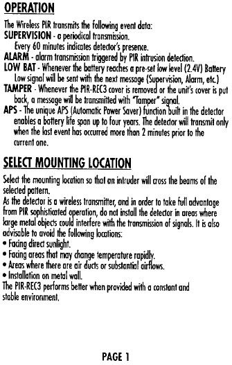
.60 lhs Pel Immune
.High ~ile Ught Immunity
.50 x 50 Covefoge
.Quod 8ement PIR
.WoIl Of Ce~ing Moontlnduded
.long Ronge Curtain 10ptW)
.Ultra High While lighllmmunity lens IOpliord) I.Calibration Free Installation
.Slate-of-lhHrt wireless PIR
.low current ASIC PIR Te<hnology
.Powered by 0 3Vo!IlithftJm bonery
.Bonery life: up to 4 years
.Bull in Aulomoti( Power Saver lAPS)
.low Baftery (ondition signm tronlln~sion
.Tesl mode for PIR [overage and RF signal
Venioo_1
OPERATION
The Wireless PIR tronsmitl the following event dolo:
SUPERVISION.o periodicol tronsm~on.
Every 60 minutel indicotes detector's presence.
AlARM. olorm tronsmission triggered by PIR intrusion detectKln
LOW BAT. Whenever the buttery reachel 0 pre-set k>w level (2.4V) Bottery
Low signol will be sent with the next message (Supervision, Alorm, ett)
TAMPER -Whenever the PlR-RE(3 cover is removed or the unit's cover is put
buck 0 melsage will be tronsmiffed with 10mper' signal.
APS -The un~ue APS (Auto~fic Power Saver) function built in the detector
enoblel 0 battery life spun up to four years- The detector will tronsmit on~
when the kist event hos O(curred ~re thon 2 minufel prior 10 the
current one-
SELECT MOUNTING LOCATION
Select the ~unfing klcafion so thot on intruder will (Joss Ihe beams of the
selected pottern.
As the detector is 0 wireless tronsmiffer, ond in order to toke full odvontoge
from PIR ~hisfiroted operotKln, do not instoll the detector in oreos where
klrge metol objects could interfere with the tronsmission of signals- It is olso
odvisable to ovoid the following klrotions
.Facing direct sunlight.
.Facing oreas thot ~y chof!ge temperoture ropidlv.
.Areos where there ore oir ducts or substontiol oirflows.
.Instollofion on metol woll-
The PIR-RE(3 performs better when provided wifh 0 constont ond
stobie environment.
PAGE 1
MOUNTING THE DETEGOR
~ Secure Wireless Pet Immune PIR can be mounted in a corner nke standard
PIR's or by insfolling the included oordware can be eosi~ mourned to a WlJII
or ceiling
Standard Corner Mounti~
1 ) Remove the screw at the bonom of the case and open the PIR.
2) (oreful~ mourn using the screw guides for flat surface mourning or corner
mourning. It is oc(eptob~ to bend the ornenno ~ightfy in order to mourn
the case to the WlJII or desired surface
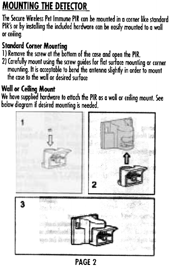
Wall or Ceiung Mount
We have supplied hardware 10 onoch the PIR as a WlJII or ceiling mourn. See
below diagram ~ desired mourning is needed.
it[If'
2
3
PAGE 2
MOUNTING THE DETECTOR continued
"
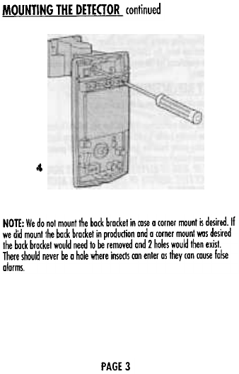
NOTE: We do not mount the bock brocket in cose a corner mount ~ desired. If
we did mount the bock bracket in production and a corner mount VIlIS desired
the bock bracket wou~ need to be removed and 2 holes would then exist.
There shou~ never be a ho~ where insects con enter as they can couse false
alarms
PAGE 3
SETTING UP THE DETECTOR
The sensitivity ad[ustmenf switch sels up !he detectar for narrool ar harsh
enviranment canditian.
Setting !he Sensnivity Adjustment (Puke WKI!h) Jumper
.Pasitian 1= Normal
.PosnKJn AUTO = Harsh
The 'I' position setting is for normal aperation.
The 'AUTO' posnion setting is for harsh environmentlacations wnil air draMs
or small anirools.
Se"ing the Pet Immunity Level
Slide tlie swnch fa 25Kgs for larger pets up 10 60lbs or 15kgs lor smaller pets
under 30lbs
ENROLLING THE PIR-REC3
The enrolling process of Ihe PIR.REC3 ~ lhe some os odding ony olher PIR.
Although lhe REC3 will eventuol~ work with every manufocturer leIs ossume
you desire 10 make Ihe PIR.REC3 work with an Ademco pane!. The pro<ess is
similor as enrolling 0 5890PI.
I ) Enter Ademco Progromming
2) Go to the Zone you desire
31 When the keypad asks you to 'learn Serial Number' Prell and HOLD Ihe
program buffon located on the PIR board for 2 seconds. The PIR will then
send 0 ser~s of 'tesllransmillions.
4) Verify the loop is set 10 '2'.
If you teach the serm! number by pressing the tamper switch, Ioo~ 4 will be
displayed. You musf then manual~ change the loop number 10 2lrom
Ihe keypad.
PAGE 4
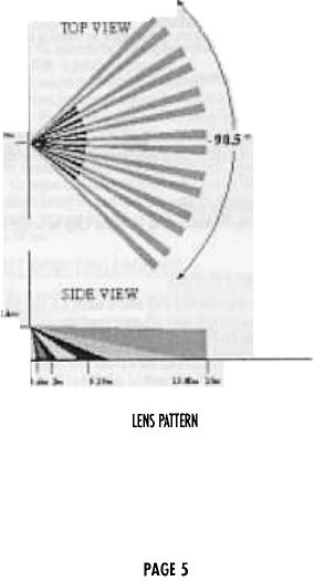
lENS PATTERN
PAGE 5
MlliRr
A 3 V I~hium battery powe~ the unil. Thanks 10 the exdusive APS (Automatic
Power Saver) characterisliCl, the ba"ery provides oooul4 years of continuous
\iPeration (depending on the amount of alarms). If the ba"ery reaches a
factory presellaw level, the lOW BATTERY signal will be senl and the detector
w~1 remain operational for 30 days giving enough lime 10 replace Ihe 3V
lilhKJm ba"ery
BATTERY REPLACEMENT
0 Remove screw at the bo"om of Ihe case to open.
0 Take oul the old battery
0 Using a flat head screwdriver shar1the Iwa pins located behind the positive
side of the ba"ery holder forI 0 seconds This monetary shart will dischorge
011 remaining power from the cirruifl allowing a 'fresh' power up
olnsloll 0 new battery according 10 polarity.
CAUTION ill RISK OF EXPLOSION IF BATTERY IS REPLACEO BY AN
INCORREa TYPE. DISPOSE OF USED BATTERIES ACCORDING TO
THE INSTRUalONS.
PAGE 6
TECHNICAL SPECIFICATIONS
Data Prato<oI Serure Wireless
Modulation Type ASK
Event Transrn~ian Alann, Tamper, Test, Supervision,
Law Bot
Supervision TH11ing 60 minutes
Oete<tian Method Quod Bement
Oete<tian Speed 0.3 -1.S mise!
Lens Type Spherical Hard Lens
Oete<tian Coverage 90.S (SO x SO)
Environment Condition Jumper for Nann~ or Harsh selection
Battery liIhium. 3V Type: CR 123A
Current Consumption
Standby -10 mA
Transmission -16 mA
Power Saving APS (Automatil Power Saver)
Instoll Test Modes LED Indirofor (RF & Opfic) Walk Test and
Alann Transmission Tesf
Operating temperature .1 O{C to +SO{C
Range
Dimensions 61 mmX 12OmmXSOmm
(2.43'w X 4.2S'h X 2'd)
Federal COnIIMIkat- Commission !FCC Slatement
Jhi,dewe (omp~es.;~ port lSol~e FCC Ru~. Operatian is ",bjed 10 !he lollo.;ng
~ condition, (1) l1Iis devile IntIy nat rouse harmful interfere",e, and (2) ~i, de."
must accept any interferelKe roceiwd, including inlerlere",e thot moy cause
undesired aperation.
PAGE 7
Changes or modifications not expressly approved by the party responsible for
compliance could void the user's authority to operate the equipment.