Securitron R100H Installation Instructions R100 1H I 500 24050 20A

User Manual: Securitron R100H Installation Instructions Installation Instructions

Open the PDF directly: View PDF PDF.
Page Count: 6

Scroll down to view the document on your mobile browser.
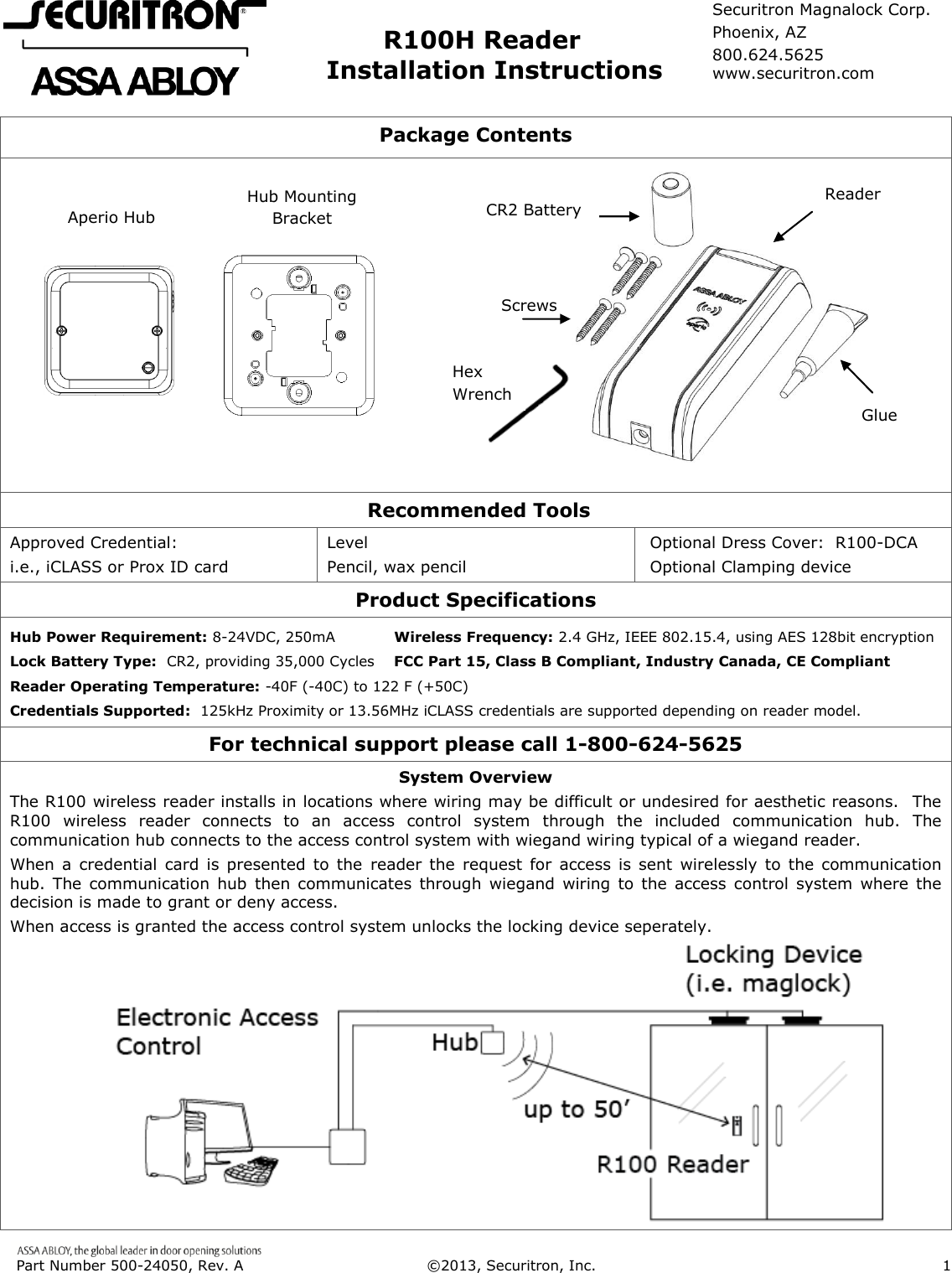
 Part Number 500-24050, Rev. A  ©2013, Securitron, Inc.                      1                     R100H Reader             Installation Instructions  Package Contents                                  Recommended Tools Approved Credential: i.e., iCLASS or Prox ID card Level Pencil, wax pencil Optional Dress Cover:  R100-DCA Optional Clamping device Product Specifications Hub Power Requirement: 8-24VDC, 250mA            Wireless Frequency: 2.4 GHz, IEEE 802.15.4, using AES 128bit encryption Lock Battery Type:  CR2, providing 35,000 Cycles    FCC Part 15, Class B Compliant, Industry Canada, CE Compliant Reader Operating Temperature: -40F (-40C) to 122 F (+50C)  Credentials Supported:  125kHz Proximity or 13.56MHz iCLASS credentials are supported depending on reader model. For technical support please call 1-800-624-5625 System Overview The R100 wireless reader installs in locations where wiring may be difficult or undesired for aesthetic reasons.   The R100  wireless  reader  connects  to  an  access  control  system  through  the  included  communication  hub.  The communication hub connects to the access control system with wiegand wiring typical of a wiegand reader. When a credential  card is  presented  to the  reader the  request  for  access  is  sent  wirelessly to  the  communication hub. The  communication  hub  then  communicates  through  wiegand  wiring  to the  access  control  system  where  the decision is made to grant or deny access. When access is granted the access control system unlocks the locking device seperately.            Aperio Hub Hub Mounting Bracket Glue Reader Screws CR2 Battery Hex Wrench Securitron Magnalock Corp. Phoenix, AZ 800.624.5625 www.securitron.com
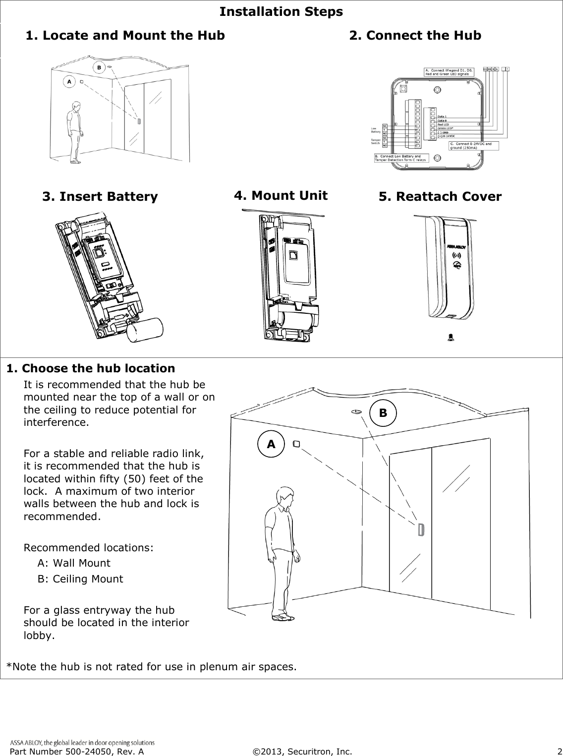
 Part Number 500-24050, Rev. A  ©2013, Securitron, Inc.                      2   Installation Steps                    1. Choose the hub location It is recommended that the hub be mounted near the top of a wall or on the ceiling to reduce potential for interference.  For a stable and reliable radio link, it is recommended that the hub is located within fifty (50) feet of the lock.  A maximum of two interior walls between the hub and lock is recommended.  Recommended locations: A: Wall Mount B: Ceiling Mount  For a glass entryway the hub should be located in the interior lobby.  *Note the hub is not rated for use in plenum air spaces. 1. Locate and Mount the Hub 2. Connect the Hub 3. Insert Battery A B 4. Mount Unit 5. Reattach Cover

Navigation menu