Securitron WT2 Wiring And Use Instructions WTMN3A I 500 24060
User Manual: Securitron WT2 Wiring and Use Instructions Installation Instructions
Open the PDF directly: View PDF ![]() .
.
Page Count: 4
DPS
RX
TMPR
PWR ON
6
5
1
2 3
4
6
7
1
2
3
4
5
6
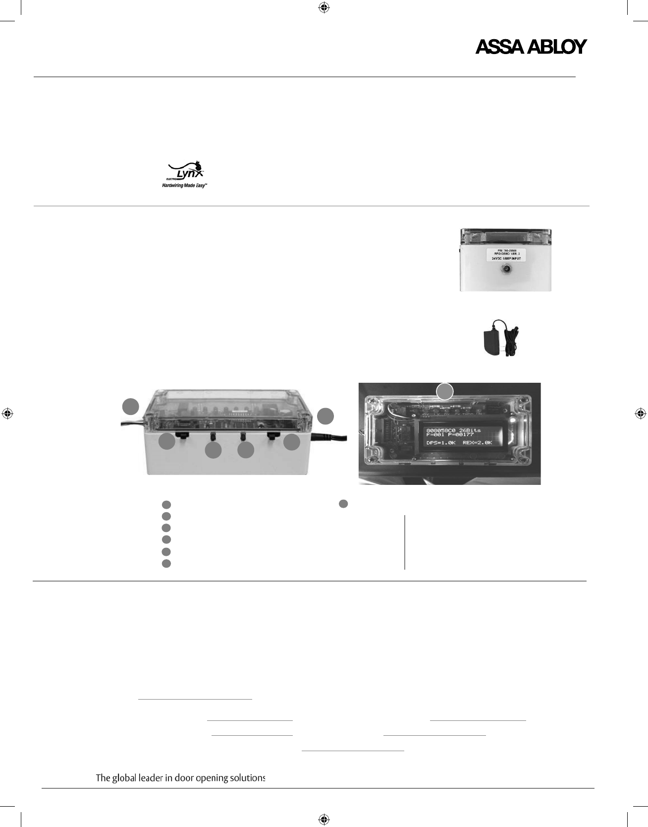
WT2 Wiegand Test Unit : Wiring and Use Instructions
CONTENTS WT2, plastic, 6.25” x 3.5” x 2.375”
TEST BOX PRODUCT
DESCRIPTION
Selectors,
Switches and Visual
Monitoring
Indicators
AC / DC adapter
FOR INSTALLATION ASSISTANCE, CALL 1-800-810-WIRE
ElectroLynx cable with Molex connectors for Integrated Wiegand products
ElectroLynx cable with Molex connector for NAC function EcoFlex electrified mortise locks
As part of their promise to provide innovative, fast and effective, and higher security solutions to their customers,
ASSA ABLOY Group companies offer ElectroLynx, a universal quick-connect system that simplifies the electrification
of the door opening. ElectroLynx™ is a trademark of ASSA ABLOY, Inc.
Designed for compatibility with ASSA ABLOY Integrated
Wiegand products and NAC Function EcoFlex mortise locks, the
ASSA ABLOY WT2 Wiegand Test Unit is a user-friendly tool that
demonstrates products features and capabilities.
The WT2 also enables field trouble shooting by verifying proper wiring,
card reader data integrity, lock functionality including: lock/unlock, door
position status, deadbolt status and REX (request-to-exit) status.
If end-of-line resistors are integrated into the product or wired into the
system, the WT2 will display these values.
If the WT2 detects line resistance above 100-Ohm on the REX or door
position sensing inputs, the unit will also display these resistance values.
Connect the WT2 directly to the lock or hinge using the provided
ElectroLynx cable.
Fail Safe /Fail Secure Selector
Open Override
Learn Button
12VDC / 24VDC Selector
To Lock
To Power Adapter
End View
Adapter
LEDs refer to the following product features:
Copyright © 2015, ASSA ABLOY Inc. All rights reserved. Reproduction in whole or in part
without the express written permission of ASSA ABLOY Inc. is prohibited.
WTMN3A – PAGE 1
Door position monitoring
Request to exit monitoring
Tamper
Indicates unit powered
DX Deadbolt monitoring
7
IMPORTANT 1. Disconnect the product to be tested from access
control system before servicing.
2. Installer must be a trained, experienced
service person.
3. Wiring must comply with applicable local electrical
codes, ordinances and regulations.
4. Unit is grounded to Common (-) for Electrostatic
Discharge (ESD) protection. Use appropriate ESD
practices when handling the unit, (i.e. standard
grounding precautions). Common (-) must be
grounded to earth (EG) at the power supply.
5. Ensure that no wires are pinched or
damaged during installation.
INSTALLATION
INSTRUCTIONS
Install product on door according to manufacturer’s instructions, which can be found at
www.intelligentopenings.com or the following:
Corbin Russwin: w w w.corbinrusswin.com
HES: www.hesinnovations.com
SARGENT: w ww.sargentlock.com
Securitron: w w w.securitron.com Yale: w w w.yalecommercial.com
Catalog A7738. Receptacle
Plug
WTMN3A – PAGE 2
WT2 Wiegand Test Unit : Wiring and Use Instructions
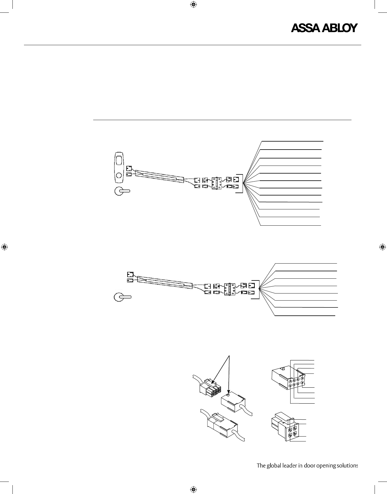
Important ElectroLynx connectors plug
and lock together in only
one way, as shown. Do NOT
force connectors together.
Reference ElectroLynx
Locking Mechanism
Copyright © 2015, ASSA ABLOY Inc. All rights reserved. Reproduction in whole or in part
without the express written permission of ASSA ABLOY Inc. is prohibited.
PIN 4 Tan (DPS)
PIN 2 (not used)
PIN 3 Pink (DPS)
PIN 2 (not used)
PIN 2
PIN 4
PIN 6
PIN 8
PIN 7
PIN 5
PIN 3
PIN 1
INTEGRATED WIEGAND
1 Black (-)
2 Red (+)
3 White (DPS)
4 Green (DPS)
5 Orange (RX)
6 Blue (RX)
1 Violet (DX)
2 Gray (DX)
Lock to
WT2 Connections
ElectroLynx Hinge with Pin Connections
Lock Cable ElectroLynx Cable to WT2
NAC FUNCTION
7 (Brown) Not Used
2 (Red) READER POS
3 (White) DATA 1
4 (Green) DATA 0
5 (Orange) RX (NO/NC)
6 (Blue) RX (COM)
9 (Violet) LOCK NEG
10 (Gray) LOCK POS
8 (Yellow) LED
11 (Pink) DPS NC
12 (Tan) DPS (COM)
1 (Black) READER NEG
CONNECT THE WT2 The WT2 is provided with two cables:
• The cable labeled ”Integrated Wiegand Locks Only” must be used with Integrated Wiegand locks.
• The cable labeled ” NAC Locks Only” must be used with NAC locks.

WT2 Wiegand Test Unit : Wiring and Use Instructions
Copyright ©2015, ASSA ABLOY Inc. All rights reserved. Reproduction in whole or in part
without the express written permission of ASSA ABLOY Inc. is prohibited.
WTMN3A– PAGE 3
Notes Failure to connect the WT2 to the lock before applying power results in
false reads.
The WT2 will accept any data from a Wiegand output and any bit structure such as
the press of a key on a keypad to trigger the lock relay.
The WT2 is capable of remembering up to the last 6 learned (programmed)
cards, whether they are the same or different.
Once single card/cards are recognized, the door device will no longer
operate by the presentation of any random card until it has been reset.
To reset the device, cycle the power while holding the learn button until it
flashes three times. Any card will then activate the lock.
The system is designed to be installation-friendly with ElectroLynx®
quick connectors.
OPERATING
INSTRUCTIONS
FOR ALL CARDS
OPERATING
INSTRUCTIONS
FOR LIMITED
To initialize the test box for all cards:
1. Connect all wires to the WT2 first.
2. Select Fail Safe or Fail Secure according to sample.
3. Select the appropriate solenoid lock voltage (12 or 24 VDC).
4. Apply power to the WT2.
5. Once the door device completes its visual and audio signaling, it will
unlock when ANY Wiegand card is presented.
To initialize the test box for a limited number of specific cards:
NUMBER OF CARDS
1. Connect all wires to the WT2 first.
2. Select Fail Safe or Fail Secure according to sample.
3. Select the appropriate solenoid lock voltage (12 or 24 VDC).
4. Apply power to the WT2.
5. Press and hold the Learn button.
6. Present a card to the lock.
7. That card is recognized and added to the list of cards that will unlock the
lock. Other cards will not work until each is presented while holding down
the learn button.
Power Input AC 100 – 240V 600mA 50Hz/60Hz
Power Output The WT2 is capable of supplying a total of 900 MA output to the unit under test.
The 900 MA is the total output for both reader interface and the lock.
WTMN3A – PAGE 4
WT2 Wiegand Test Unit : Wiring and Use Instructions
APPENDIX
FOR INSTALLATION A SSISTANCE, CALL 1-800-810-WIRE
Copyright © 2015, ASSA ABLOY Inc. All rights reserved. Reproduction in whole or in part
without the express written permission of ASSA ABLOY Inc. is prohibited.
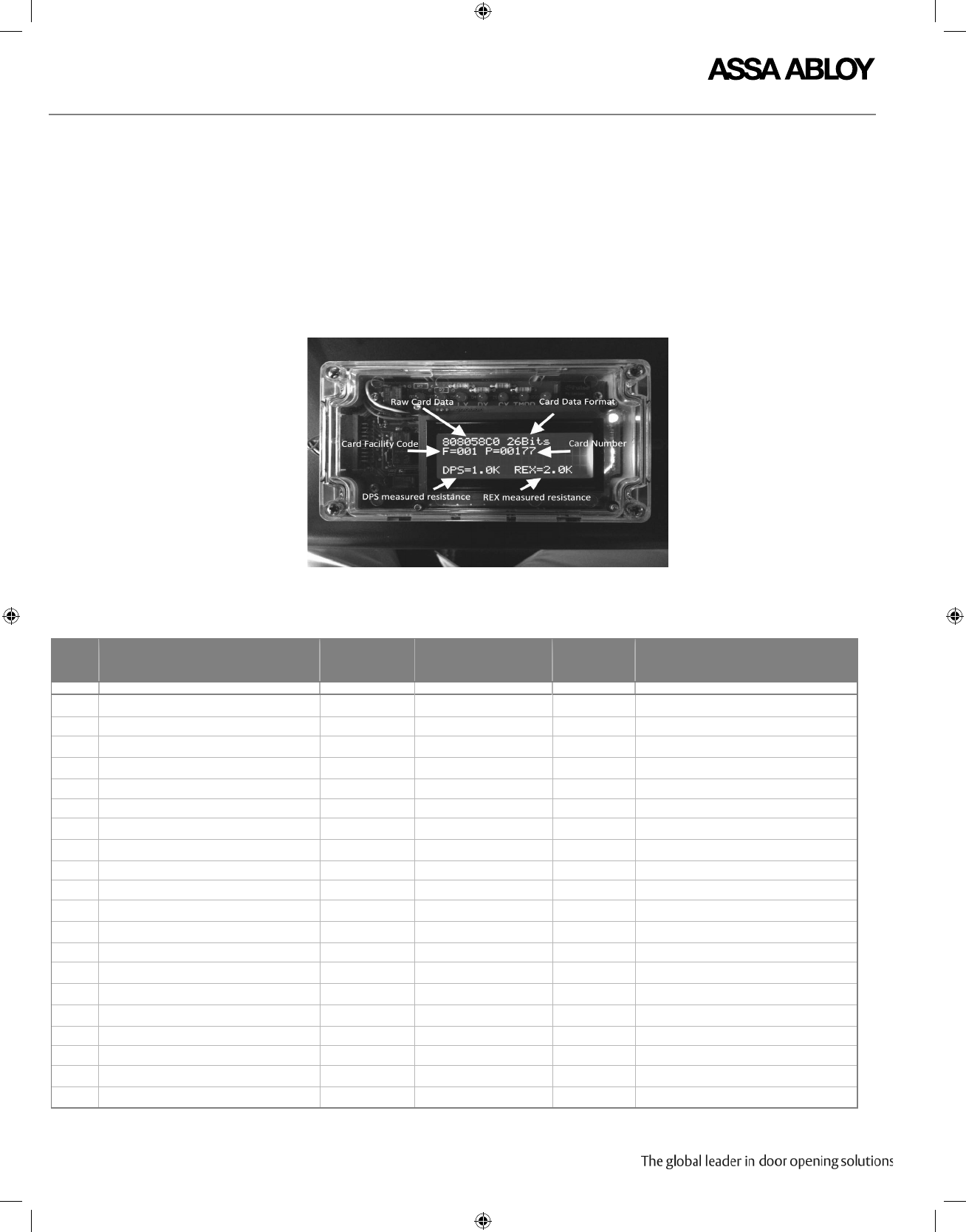
WT2
CREDENTIAL
INFORMATION
DISPLAY
The LCD display on the WT2 provides the following information:
• Measured DPS Output Resistance (if > 100-Ohm)
• Measured REX Output Resistance (if > 100-Ohm)
• Wiegand Bits Received
• Wiegand Data Received (Hexadecimal Format)
• Card Facility Code (for known HID formats)
• Card Number (for known HID formats)
PIN #
1
2
3
4
5
6
7
8
9
10
11
12
13
14
15
16
17
18
19
20
DESCRIPTION
Reader Power -
Reader Power +
Wiegand Data 1
Wiegand Data 0
REX Switch NC/NO (Keeper Switch on Strike)
REX Switch COM (Keeper Switch on Strike)
Beeper Control - Cylinder Switch
LED Control
Lock Power
Lock Relay Out
DPS Switch NC/NO
DPS Switch COM
Beeper Control
LED Control
Dead Bolt Switch NC/NO
Latch Bolt Switch NC/NO
Cylinder Switch NC/NO - Spare
Tamper Relay NC/NO
Lock Power + / Controller Power
Lock Relay IN
WIRE COLOR
Black
Red
White
Green
Orange
Blue
Brown
Yellow
Violet
Grey
Pink
Tan
Brown
Yellow
White/Orange
White/Red
White/Black
White/Blue
Red
Violet
WIRE HARNESS
(Wiring diagram on
following page)
Interface TS1
Not Used
Interface TS4
InterfaceTS4
Interface TS4
Interface TS4
Not Used
Not Used
Not Used
Not Used
InterfaceTS4
Interface TS4
InterfaceTS4
Interface TS4
AUX Board TS1 AUX-2
AUX Board TS1 AUX-1
Not Used
Interface TS1
Interface TS1
Lock Relay TS4
ELYNX CABLE
(Wiring
diagram on
previous page)
8 PIN -1
8 PIN -2
8 PIN -3
8 PIN -4
8 PIN -5
8 PIN -6
Not Used
8 PIN -8
4 PIN -1
4 PIN -2
4 PIN -3
4 PIN -4
Not Used
Not Used
Not Used
Not Used
Not Used
Not Used
Not Used
Not Used
Ground
+12 VDC always
+5 goes to ground for data 1 bit
+5 goes to ground for data 0 bit LED on when
REX used or when Keeper closed
LED on when REX used or when Keeper closed
+5 goes to ground to turn LED Green
Ground
* Lock Power+
LED on when switch closed
LED on when switch closed
+5 to turn Beeper on
+5 to turn LED Green LED on when secure
(Dead Bolt extended)
** LED on when secure (Latch Bolt extended)
LED on when Key in use (future)
LED on when Tamper true
Switch selected 12VDC or 24VDC
* Lock Control
MISCELLANEOUS COMMENTS
