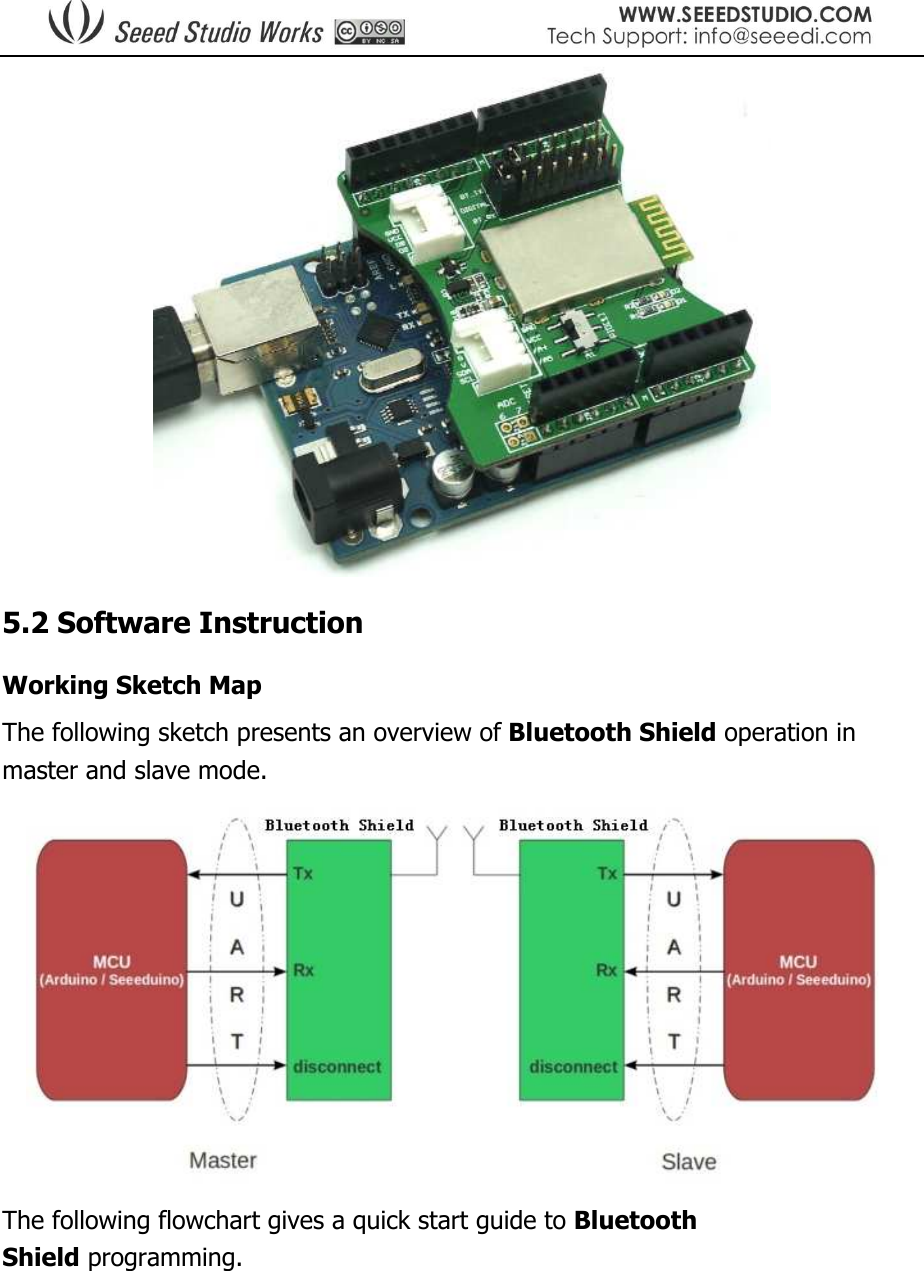
Seeed Technology BTSHIELD Bluetooth Shield User Manual manual

Seeed Technology Limited Bluetooth Shield manual

User Manual

 Revision History Revision  Descriptions  Release Date Author V3  Initial release  Sep 18, 2011 Steve V3 r1  1. Change the photos. 2. Change max current to 50mA. 3. Add  the  shielding  case  to  the Bluetooth module 4. Remove the mega compatibility. Sep 23, 2011 Steve
 Bluetooth Shield (2770069) Contents  1 Introduction  2 Features  3 Specification  4.Interface function  5 Usage o 5.1 Hardware Installation o 5.2 Software Instruction 1. Introduction The Bluetooth Shield integrates a Serial Bluetooth module. It can be easily used with Arduino / Seeeduino for transparent wireless serial communication. You can choose two pins from Arduino D0 to D7 as Software Serial Ports to communicate with Bluetooth Shield (D0 and D1 is Hardware Serial Port). The shield also has two Grove connectors (one is Digital, the other is Analog) for you to install Grove modules.
 2. Features  Seeeduino/Arduino compatible  Up to10m communication distance in house without obstacle  UART interface (TTL) with programmable baud rate (SPP firmware installed)  Default Baud rate: 38400, Data bits: 8, Stop bit: 1, Parity: No parity  Default PINCODE:”0000”  A full set of configuration commands  On board PCB Antenna  FCC ID Certificated  3. Specification Contents Item  Min  Typical  Max  Unit Voltage  2.8  3.3  3.5  VDC Current  3  /  50  mA Communication Distance(in house)  /  /  10  m Protocol  Bluetooth V2.0 with SPP firmware  / Interface  Uart Serial Port(TTL)  / Supported Baudrate  9600, 19200, 38400, 57600, 115200, 230400, 460800  bps ESD contact discharge  ±4  KV ESD air discharge  ±8  KV Dimension  57.4x45.3x19.4  mm Net Weight  10±2  g     4. Interface Function
  Pad Type  Description PIO1  Status instruction port of Bluetooth module can be read by Arduino A1 port: low-disconnected, high-connected. BT_RX  UART Data input of Bluetooth module BT_TX  UART Data output Bluetooth module Two Grove connectors  One is Digital (D8 and D9), the other is I2C/Analog (A4 and A5).  5. Usage 5.1 Hardware Installation Plug the Bluetooth Shield onto Arduino/Seeeduino and then connect the board to PC using USB cable.
  5.2 Software Instruction Working Sketch Map The following sketch presents an overview of Bluetooth Shield operation in master and slave mode.  The following flowchart gives a quick start guide to Bluetooth Shield programming.
  Commands to change default configuration 1. Set working MODE \r\n+STWMOD=0\r\n Set device working mode as client (slave). Save and Rest. \r\n+STWMOD=1\r\n Set device working mode as server (master). Save and Rest. Note: \r\n is necessary for operation and the value of are 0x0D 0x0A in Hex. \r and \n represent carriage-return and line-feed (or next line), 2. Set BAUDRATE
 \r\n+STBD=115200\r\n Set baudrate 115200. Save and Rest. Supported baudrate: 9600, 19200, 38400, 57600, 115200, 230400, and 460800. 3. Set Device NAME \r\n+STNA=abcdefg Set device name as “abcdefg”. Save and Rest. 4. Auto-connect the last paired device on power \r\n+STAUTO=0\r\n Auto-connect forbidden. Save and Rest. \r\n+STAUTO=1\r\n Permit Auto-connect. Save and Rest. 5. Permit Paired device to connect me \r\n+STOAUT=0\r\n Forbidden. Save and Rest. \r\n+STOAUT=1\r\n Permit. Save and Rest. 6. Set PINCODE \r\n +STPIN=2222\r\n Set pincode “2222”, Save and Rest. 7. Delete PINCODE(input PINCODE by MCU) \r\n+DLPIN\r\n  Delete pincode. Save and Rest. 8. Read local ADDRESS CODE \r\n+RTADDR\r\n  Return address of the device. 9. Auto-reconnect the device when they loss connection. \r\n+LOSSRECONN=0\r\n Forbid auto-reconnecting.
 \r\n+LOSSRECONN=1\r\n Permit auto-reconnecting. Commands for Normal Operation: 1. Inquire a) Master \r\n+INQ=0\r\n  Stop Inquiring \r\n+INQ=1\r\n  Begin/Restart Inquiring a) Slave \r\n+INQ=0\r\n  Disable been inquired \r\n+INQ=1\r\n  Enable been inquired When +INQ=1 command is successful, the red and green LEDS blink alternatively. 2. Bluetooth module returns inquiring result \r\n+RTINQ=aa,bb,cc,dd,ee,ff;name\r\n Serial Bluetooth device with the address “aa,bb,cc,dd,ee,ff” and the name 3. Connect device \r\n+CONN=aa,bb,cc,dd,ee,ff\r\n  Connect to a device with address of "aa,bb,cc,dd,ee,ff” 4. Bluetooth module requests inputting PINCODE \r\n+INPIN\r\n 5. Input PINCODE \r\n+RTPIN=code\r\n Example: RTPIN=0000, Input PINCODE which is four zero.
 6. Return status \r\n+BTSTA:xx\r\n  xx status: 0 - Initializing 1 - Ready 2 - Inquiring 3 - Connecting 4 - Connected (Note: This is not a command, but the information returned from the module after every command)  Warning: Changes or modifications  to this unit not expressly approved by the party responsible for compliance could void the user’s authority to operate the equipment.  NOTE:    This  equipment  has  been  tested  and  found  to  comply  with  the  limits  for  a  Class  B  digital device,  pursuant  to  Part  15  of  the  FCC  Rules.  These  limits  are  designed  to  provide  reasonable protection  against harmful interference in  a residential installation.  This equipment  generates, uses and  can  radiate  radio  frequency  energy  and,  if  not  installed  and  used  in  accordance  with  the instructions, may cause harmful interference to radio communications.  However,  there  is  no  guarantee  that  interference  will  not  occur  in  a  particular  installation.    If  this equipment does cause harmful interference to radio or television reception, which can be determined by turning the equipment off and on, the user is encouraged to try to correct the interference by one or more of the following measures:   Reorient or relocate the receiving antenna.  Increase the separation between the equipment and receiver.  Connect the equipment into an outlet on a circuit different from that to which the         receiver is connected.  Consult the dealer or an experienced radio/TV technician for help.  This  device  complies  with  Part  15  of  the  FCC  Rules.  Operation  is  subject  to  the  following  two conditions:     (1) this device may not cause harmful interference, and     (2)  this  device  must  accept  any  interference  received,  including  interference  that  may  cause undesired operation.   OEM Installation Instruction  FCC Radiation Exposure Statement: This equipment complies with FCC radiation exposure limits set forth for an uncontrolled environment. This equipment is installed and operated without distance limited between the radiator & your body. This transmitter must not be co-located or operating in conjunction with any other antenna or transmitter. This device is intended only for OEM integrators under the following conditions:    The transmitter module may not be co-located with any other transmitter or antenna.
  As long as the condition above are met, further transmitter test will not be required. However, the OEM integrator is still responsible for testing their end-product for any additional compliance requirements required with this module installed (for example, digital device emissions, PC peripheral requirements, etc.).  Maximum antenna gain with this device is -1dBi.  IMPORTANT NOTE: In the event that these conditions cannot be met (for example certain laptop configurations or co-location with another transmitter), then the FCC authorizations are no longer considered valid and the FCC ID cannot be used on the final product. In these circumstances, the OEM integrator will be responsible for re-evaluating the end product (including the transmitter) and obtaining separate FCC authorizations.  End Product Labeling The final end product must be labeled in a visible area with the following: “Contains Transmitter Module FCC ID: Z4T-BTSHIELD” or “Contains FCC ID: Z4T-BTSHIELD” .  Manual Information That Must be Included The user’s manual for end users must include the following in-formation in a prominent location. IMPORTANT NOTE: To comply with FCC RF exposure compliance requirements, the antenna used for this transmitter must not be collocated or operating in conjunction with any other antenna or transmitter.  Other notes: Bluetooth Shield modules have been built or under development for near body exposure applications. Because absorption rate testing (commonly known as SAR or Specific absorption rate) is not modularly transferable for FCC/IC. Thus, if the module is installed in the final device, the end user is still responsible to evaluate RF exposure testing (for USA, please refer to the following): • FCC Part 1.1307 • FCC Part 2.1091 Mobile Devices • FCC Part 2.1093 Portable Devices

Navigation menu