Seeed Technology EAGLEYE530S IoT Development Platform User Manual ARTIK 530 Development Board User Guide
Seeed Technology Co., Ltd. IoT Development Platform ARTIK 530 Development Board User Guide
Users Manual
Seeed Eagleye 530s User Guide

Seeed Technology Co., Ltd. Eagleye 530s User Guide
2
VERSION HISTORY
Revision
Date
Description
Maturity
V1.0
2018.04.25
Eagleye 530s User Guide.
Release

Seeed Technology Co., Ltd. Eagleye 530s User Guide
3
HANDLING GUIDE
Precaution against Electrostatic Discharge
When using the Eagleye 530s ensure that the environment is protected against static electricity:
Contamination
Do not use the Eagleye 530s in an environment exposed to dust or dirt adhesion.
Temperature/Humidity
The Eagleye 530s Development Board is sensitive to:
1. Environment
2. Temperature
3. Humidity
High temperature or humidity deteriorates the characteristics of Eagleye 530s, therefore, do not store or use the Eagleye
530s under such conditions.
Mechanical Shock
Do not to apply excessive mechanical shock or force to the Eagleye 530s.
Chemical
Do not expose the Eagleye 530s to chemicals. Exposure to chemicals leads to reactions that deteriorate the characteristics of
the Eagleye 530s.
EMS (Electro Magnetic Susceptibility)
Strong electromagnetic waves or magnetic fields may affect the characteristics of the Eagleye 530s during the operation
under insufficient PCB circuit design for Electro Magnetic Susceptibility (EMS).
Seeed Technology Co., Ltd. Eagleye 530s User Guide
7
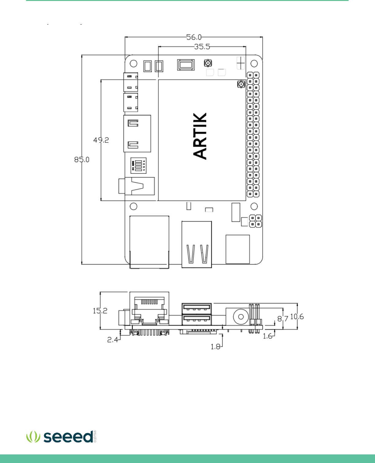
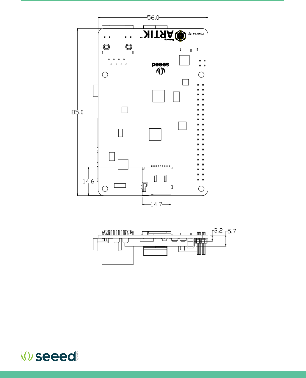
Figure 4. Mechanical Drawing Eagleye 530s all dimensions are in [mm]

Seeed Technology Co., Ltd. Eagleye 530s User Guide
8
EAGLEYE 530S MAIN FEATURES
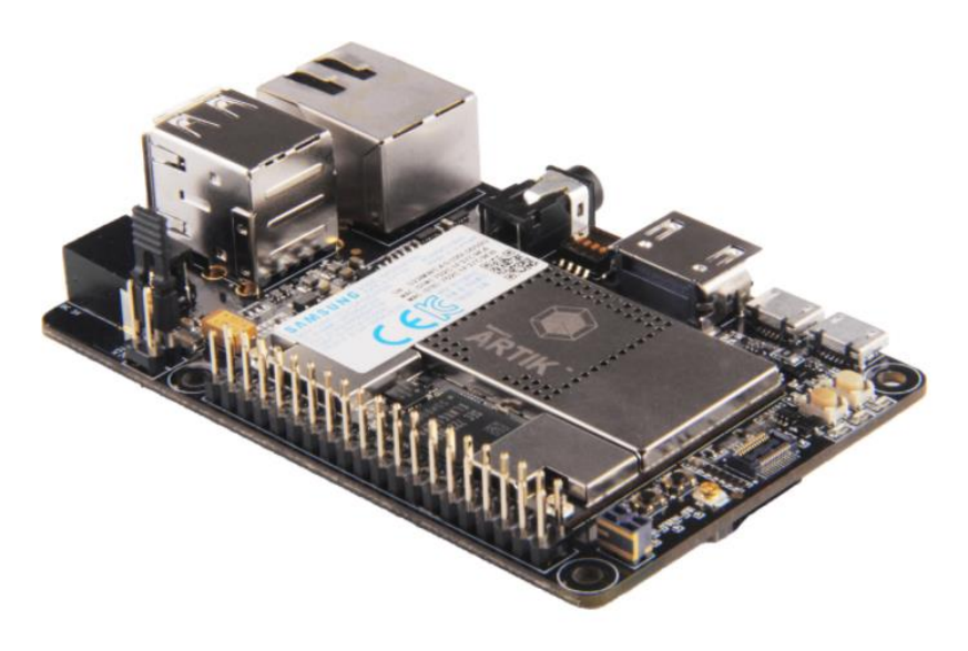
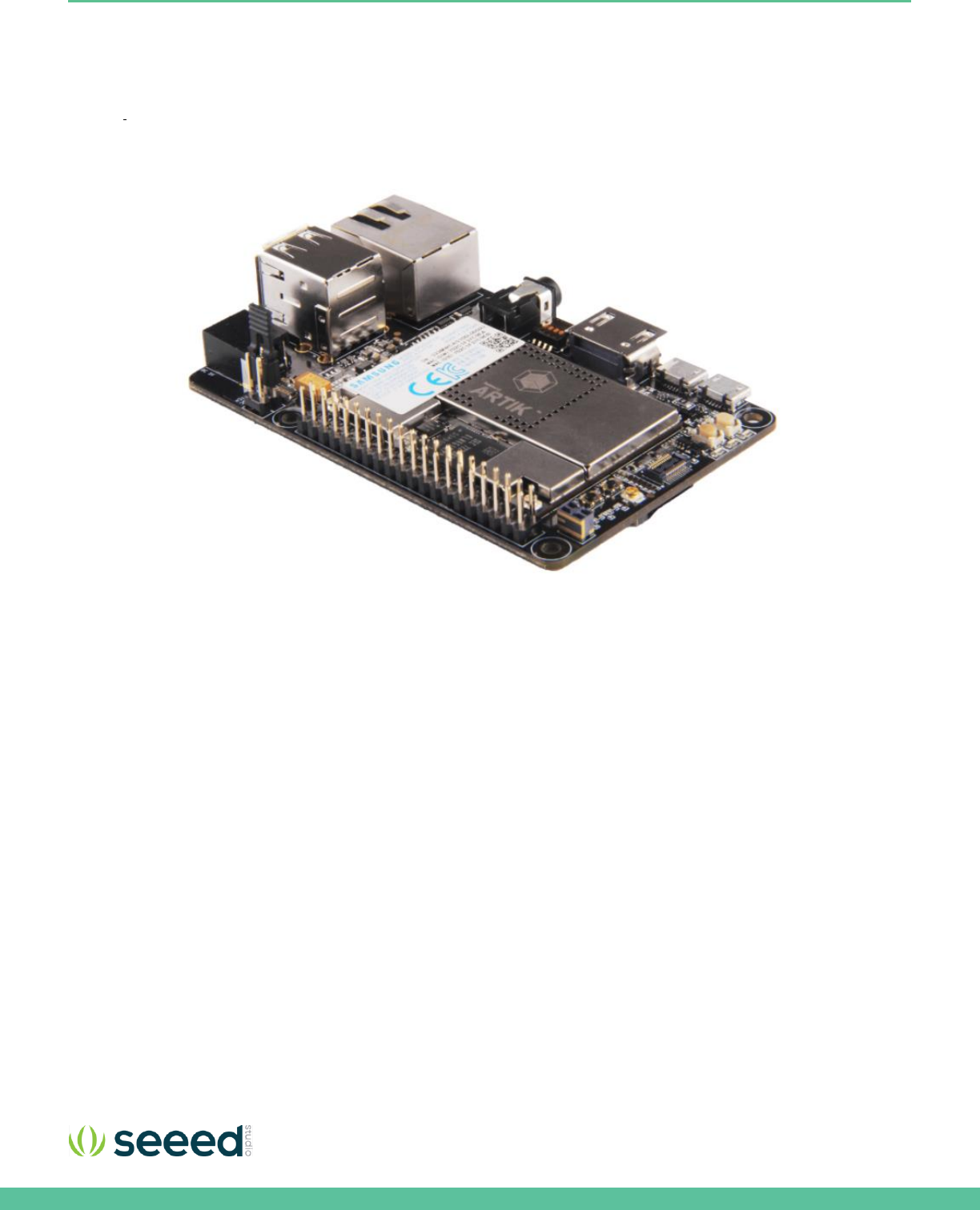
The Eagleye 530s contains an ARTIK 530 Module. This section will describe some of the main features Eagleye 530s.
RF MODULE SPECIFICATION
Eagleye 530s is designed for IoT devices and it contains a lot of functions based on a Linux® system. Not only multimedia
functions but also network functions for example 802.11 or ZigBee®. In addition Eagleye 530s has mass storage functionality
and its own security solution. Table 1 shows the main features of the Eagleye 530s.
Table 1. Main Features of the Eagleye 530s
Processor
CPU
Quad core ARM® Cortex®-A9@1.2GHz
GPU
3D graphics accelerator
Media
Camera I/F
4-lane MIPI CSI up to 5M
(1920x1080@30fps)
Display
4-lane MIPI DSI and HDMI1.4a
(1920x1080p@60fps) or LVDS
(1280x720p@60fps)
Audio
Two I2S audio input/output
Memory
DRAM
1GB DDR3
FLASH
4GB eMMC v4.5
Security
Secure Element
Secure point to point authentication and
data transfer
Radio
WLAN
IEEE 802.11a/b/g/n, dual band SISO
Bluetooth®
4.2 (BLE+Classic)
802.15.4
ZigBee®/Thread
Power Management
PMIC
Provides all power of the ARTIK 530s
Module using on board bucks and LDO’s
Interfaces
Ethernet
10/100/1000Base-T MAC (External PHY
required)
Analog and Digital I/O
GPIO, UART, I2C, SPI, USB Host, USB
OTG, HSIC, ADC, PWM, I2S, JTAG
RF PARAMETERS(FOR EU)
Bluetooth: 2402MHz to 2480MHz, Maximum E.I.R.P. 9.83dBm
Wi-Fi 2.4G: 2412MHz to 2472MHz, Maximum E.I.R.P. 17.36dBm
Wi-Fi 5G: 5180-5240MHz, Maximum E.I.R.P. 16.36dBm; 5745- 5795MHz, 12.9dBm
Zigbee: 2405MHz to 2480MHz, Maximum E.I.R.P. 8.58dBm

Seeed Technology Co., Ltd. Eagleye 530s User Guide
10
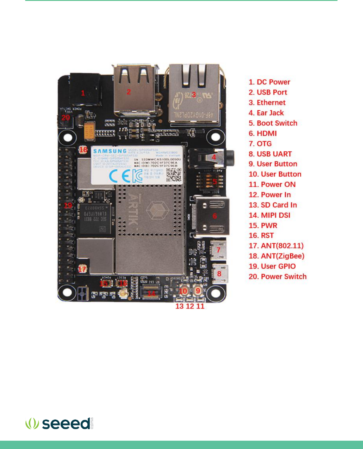
Figure 6. Bottom of Eagleye 530s
Seeed Technology Co., Ltd. Eagleye 530s User Guide
11
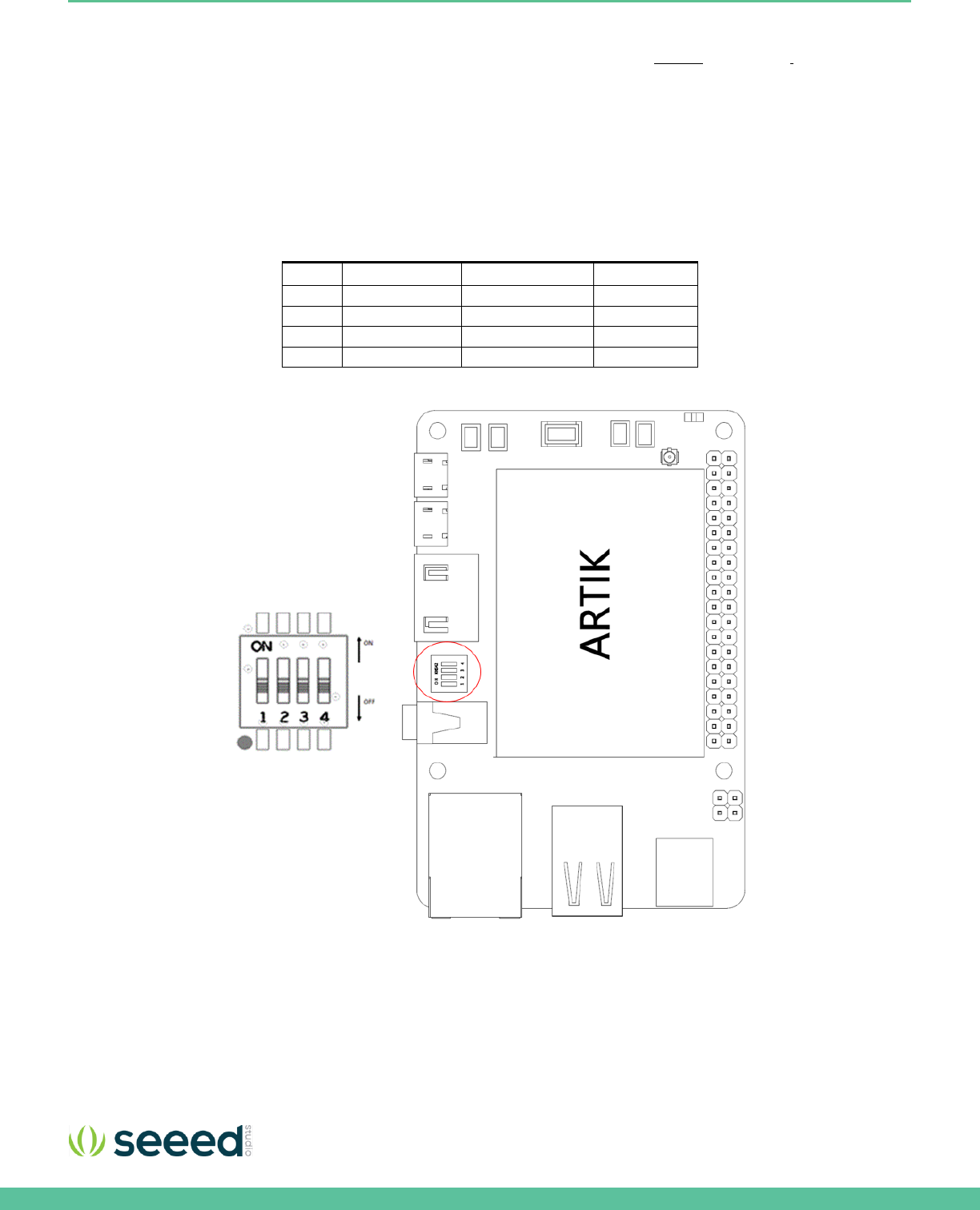
EAGLEYE 530S BOOT MODE CONFIGURATION
This section describes the various boot modes that are supported on the Eagleye 530s.
Table 2
and Figure 7
show how to
manipulate SW402 and where SW402 is located on the Interposer Board to set the various booting options that are available
on the Eagleye 530s.
When ‘eMMc 1st Boot’ is selected as a booting option, the system will first try to boot from eMMc, if this fails the system will
search for an SD Card to boot from. If booting from the SD-Card also fails the system tries to boot from USB. When choosing
the SD-Card booting option, the system starts with booting from SD, and if this fails will continue to try a USB boot. When USB
is selected as the booting mechanism of choice, only a USB boot will be attempted.
Table 2. Boot option that can be set on the Eagleye 530s
SW402
eMMc 1st Boot
SD Card 1st Boot
USB 1st Boot
1
Off
Off
On
2
Off
Off
On
3
X
X
X
4
Off
On
X
Figure 7. Eagleye 530s Booting Switch Location
Seeed Technology Co., Ltd. Eagleye 530s User Guide
13
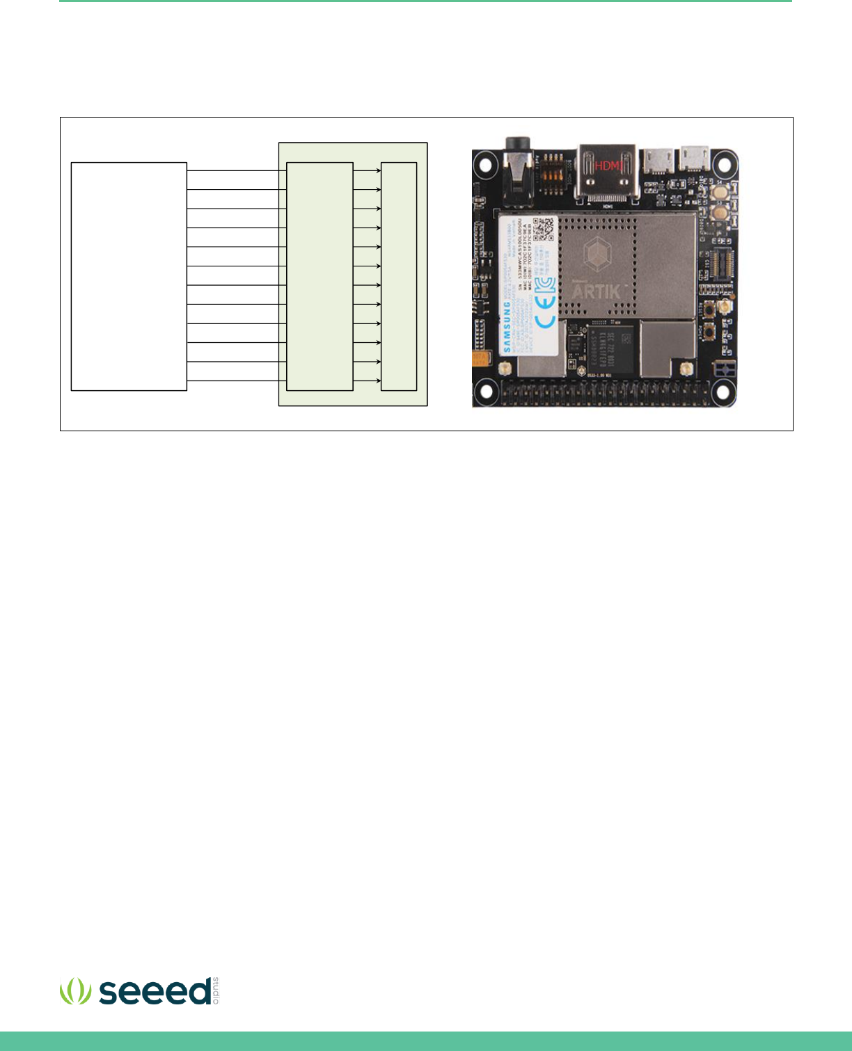
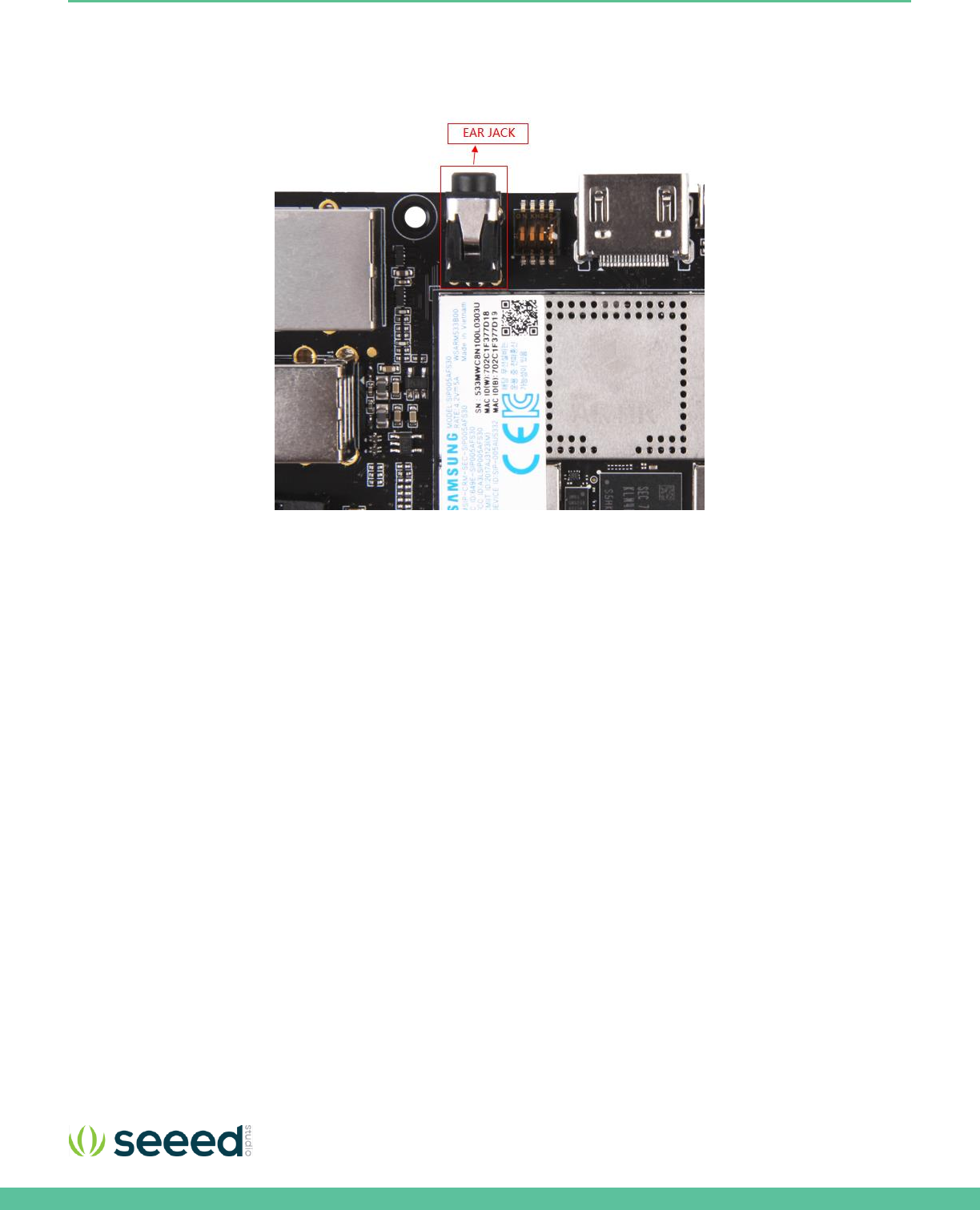
HDMI 1.4A
The Eagleye 530s has one HDMI 1.4a connector located as can be seen in Figure 9. The following video formats are supported:
1. 480p/480i @59.94Hz/60Hz, 576p/576i@50Hz
2. 720p/720i @50Hz/59.94Hz/60Hz
3. 1080p/1080i @50Hz/59.94Hz/60Hz
Figure 9. HDMI 1.4a Interface location on the Eagleye 530s
Interposer Board
HDMI
XHDMI_TX0 P
XHDMI_TX1P
XHDMI_TX2P
XHDMI_TXCP
XHDMI_TX0 N
XHDMI_TX1N
XHDMI_TX2N
XHDMI_TXCN
XHDMI_HPD
XHDMI_CEC
XHDMI_SCL
XHDMI_SDA
ARTIK 530
Module
HDMI
TPD12S01
6RKTR
Seeed Technology Co., Ltd. Eagleye 530s User Guide
14
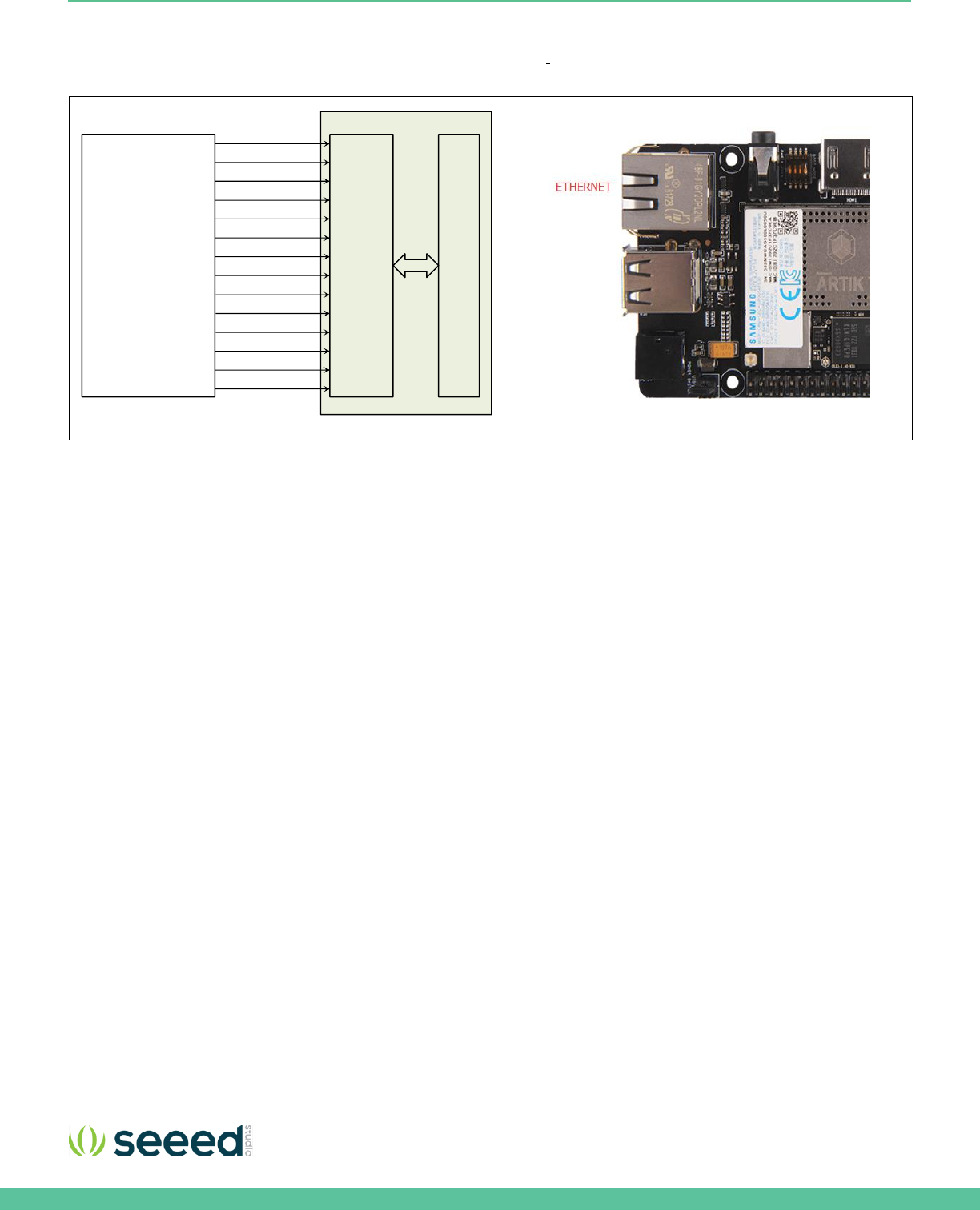
ETHERNET
The Eagleye 530s has one Ethernet Interface, its location can be seen in
Figure 10. The Ethernet Interface is based on 802.3az-
2010 complying to the Energy Efficient Ethernet (EEE) standard. The maximum theoretical speed of the interface is 1000Mbps.
Figure 10. Ethernet Interface location on the Eagleye 530s
Interposer Board
RJ45
TX DATA LANE [0 ]
TX DATA LANE [2]
TX CLOCK LANE
RX DATA LANE [0 ]
TX DATA LANE [1]
TX DATA LANE [3]
TX CTL LANE
RX DATA LANE [1]
RX DATA LANE [2]
RX DATA LANE [3]
RX CLOCK LANE
RX CTL LANE
ARTIK 530
Module Ethernet
PHY
MDC
MDIO
Seeed Technology Co., Ltd. Eagleye 530s User Guide
15
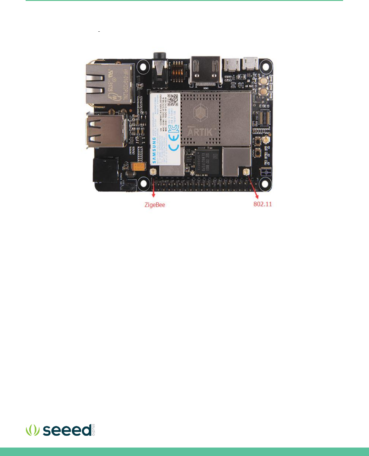
ANTENNA
If 802.11 or Bluetooth® functionality is required, the antenna which is enclosed as part of the Eagleye 530s has to be attached
to the module as depicted in
Figure 11.
Figure 11. Antenna location on the Eagleye 530s
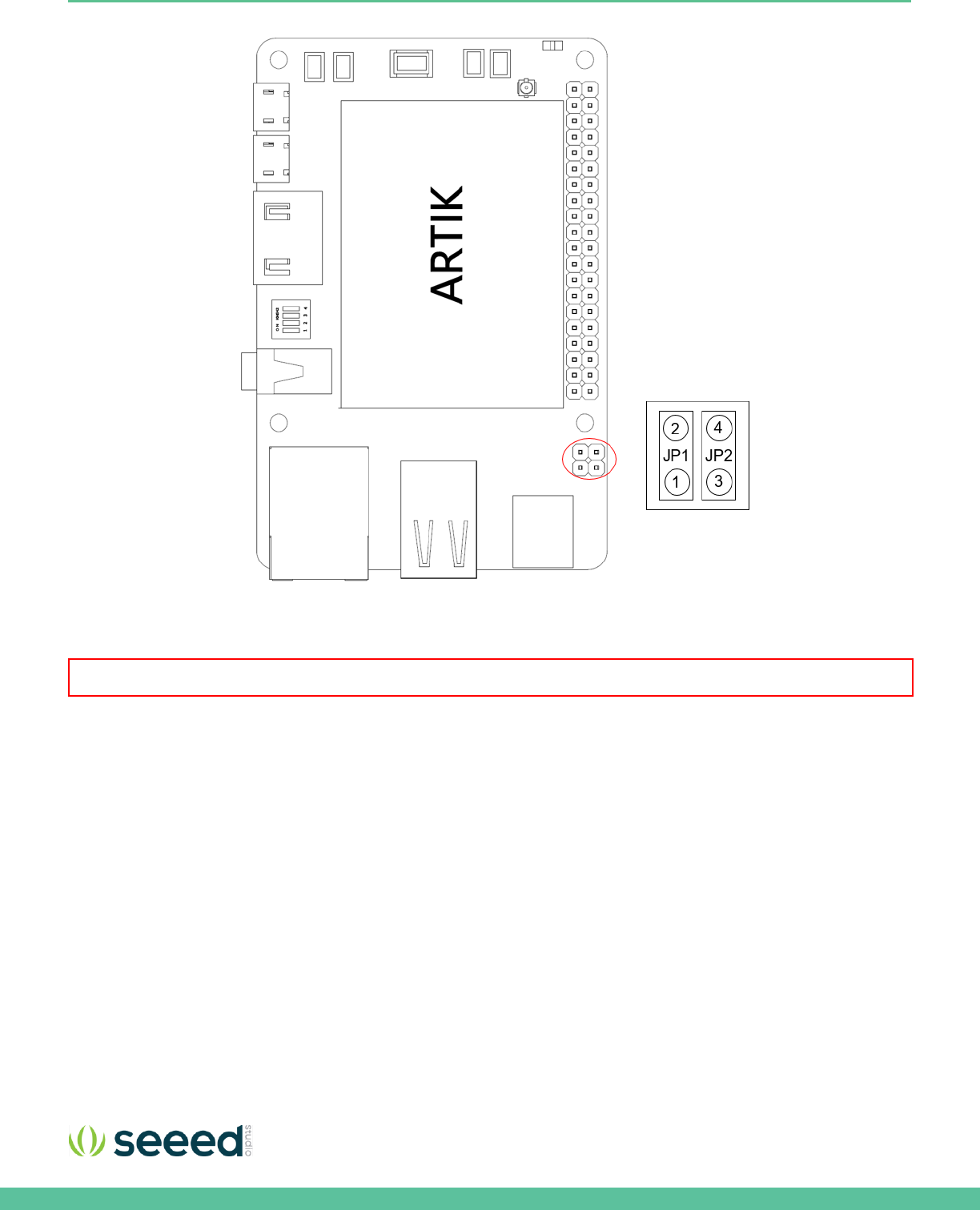
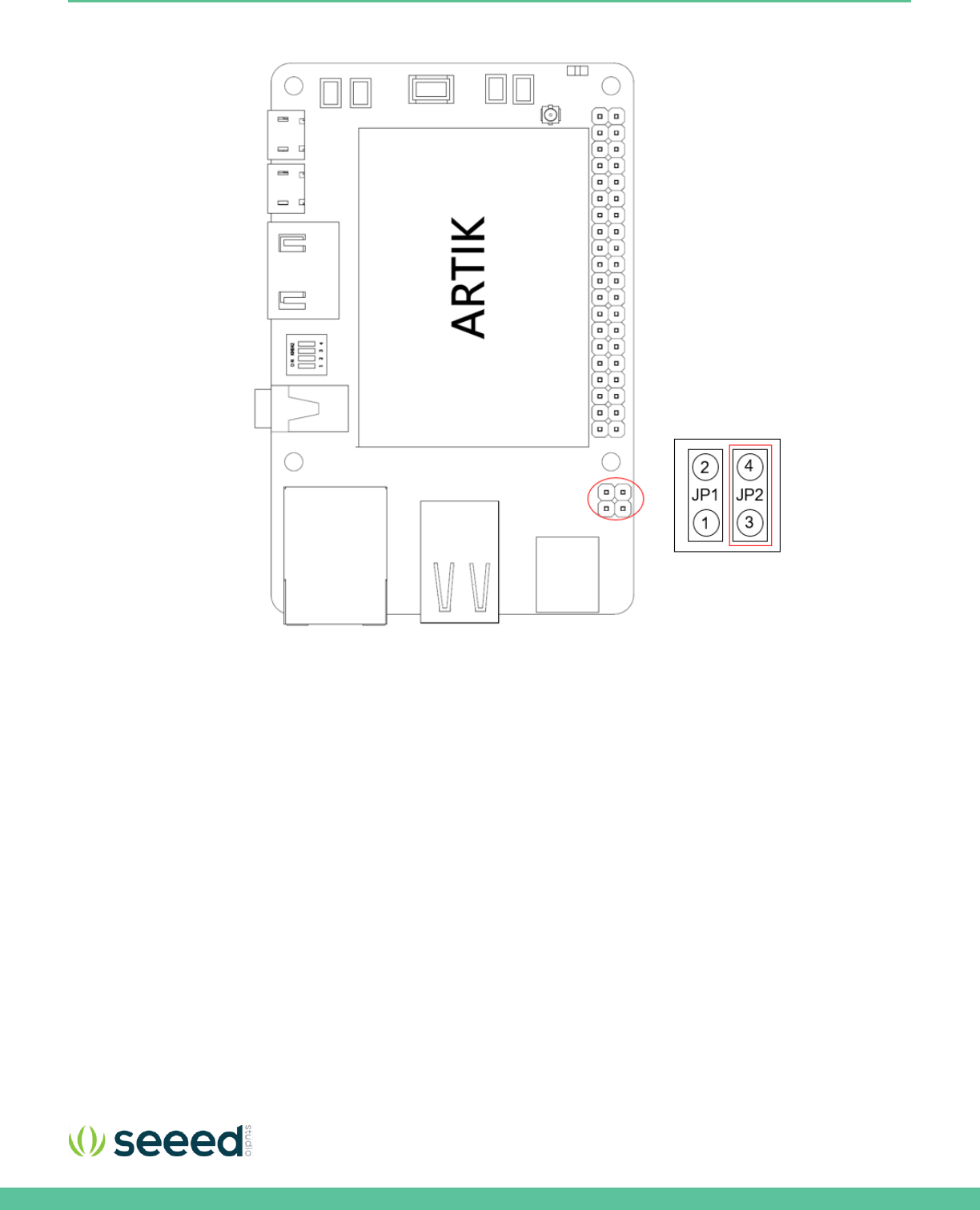
CONFIGURATION OF EXTERNAL POWER SOURCE
Through selection of the Jumpers JP1and JP2, the power source can be selected. When power is provided from a DC-5V
Adapter , jumpers JP2 will be placed and 3-4 position will be connected.
When the jumpers JP1 are in the 1-2 position, the power is provided from the Micro USB.
Figure 12 shows the default settings and how to switch between the settings. When the Eagleye 530s is used with an external
power adapter make certain that you use a 5V-2.5A adapter with a 2.1x5.5mm plug.
Seeed Technology Co., Ltd. Eagleye 530s User Guide
16
Figure 12. Jumper Interface locations JP1 or JP2 on Connectors
Warning : NEVER connect both at the same time!
Seeed Technology Co., Ltd. Eagleye 530s User Guide
17
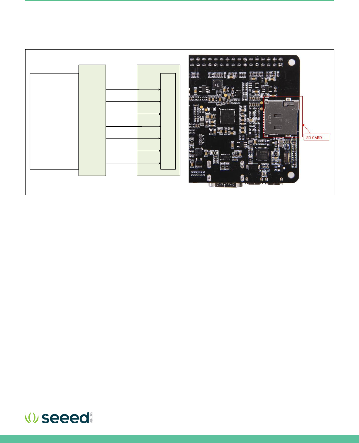
SD-CARD INTERFACE
The Eagleye 530s has one SD-CARD interface supporting SD3.0 located as can be seen in Figure 13
Figure 13. SD-Card Interface location on the Eagleye 530s
Platform Board
SD
CARD
ARTIK 530
Module
DATA [0 ]
CMD
CLK
CDN
DATA [1]
DATA [2]
DATA [3]
Interposer
Board
Seeed Technology Co., Ltd. Eagleye 530s User Guide
19
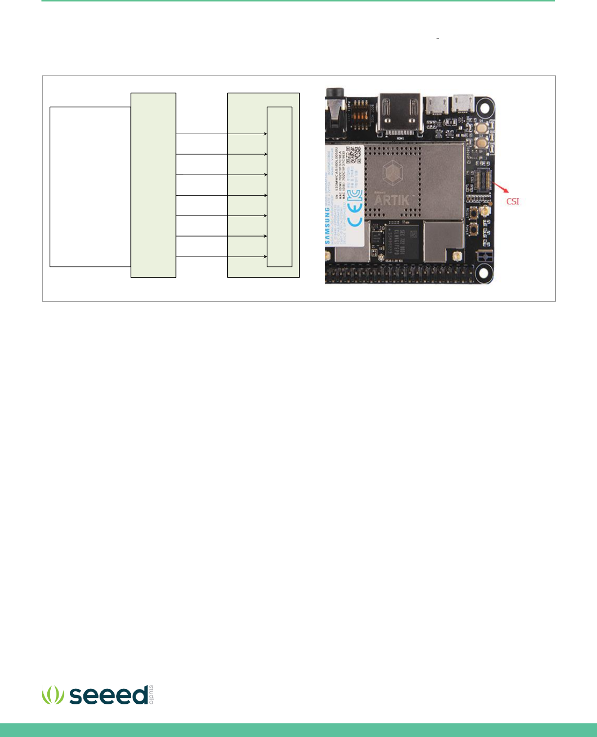
MIPI CSI INTERFACE
The Eagleye 530s has one MIPI CSI interface. The location of the MIPI CSI interface can be seen in
Figure 15. The MIPI CSI
interface can have a static resolution of 5M pixels or a dynamic resolution for video capturing of 1080P.
Figure 15. MIPI CSI Interface Location on the Eagleye 530s
Platform Board
MIPI
CSI
ARTIK 530
Module
Differential Data Lane[0]
Differential Clock Lane
I2C
LCD_Reset
Differential Data Lane[1]
Differential Data Lane[2]
Differential Data Lane[3]
Interposer
Board
Seeed Technology Co., Ltd. Eagleye 530s User Guide
20
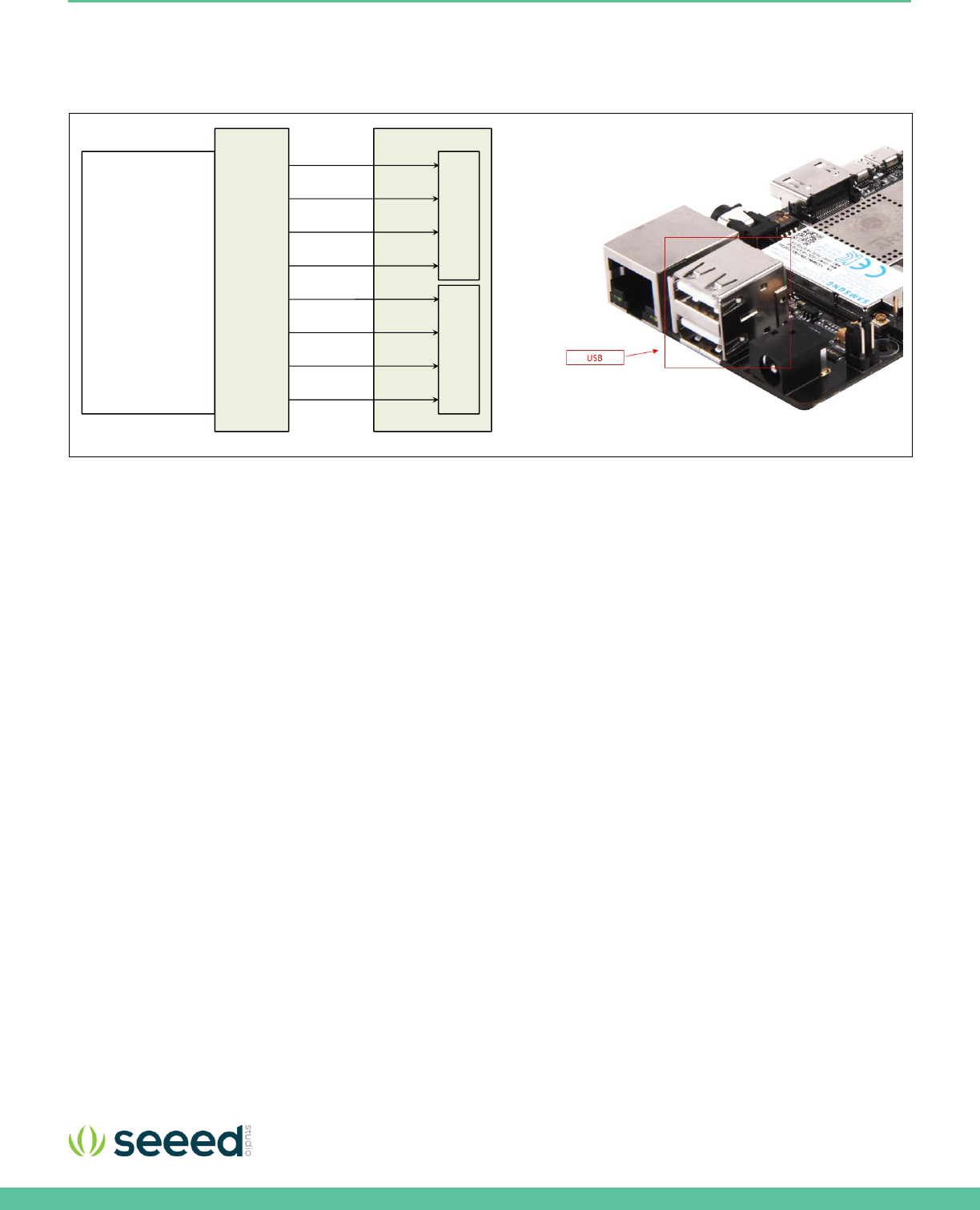
USB HOST 2.0 INTERFACE
The Eagleye 530s has two USB 2.0 Interface. The location of the USB 2.0 interface can be seen in Figure 16
Figure 16. USB2.0 Interface location on the Eagleye 530s
Platform Board
USB0
ARTIK 530
Module
Diff Data D-
VBUS
GND
Diff Data D+
USB1
Diff Data D-
VBUS
GND
Diff Data D+
Interposer
Board
Seeed Technology Co., Ltd. Eagleye 530s User Guide
21
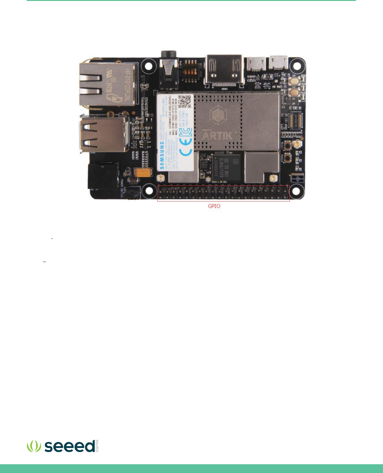
THE CONNECTOR INTERFACE
The Eagleye 530s has one expansion connector that can be seen in Figure 17 This connector enables for expansion
possibilities.
Figure 17. Expansion Connector Interface location on the Eagleye 530s
Figure 18
shows the expansion connector.
In addition
Table
3
show the pinout of the connectors with its meaning.
Seeed Technology Co., Ltd. Eagleye 530s User Guide
22
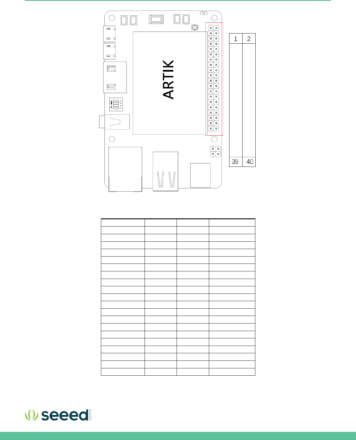
Figure 18. The expansion connector on the Eagleye 530s
Table 3. The pinout of the connectors with its meaning
Pin Name
Pin Number
Pin Number
Pin Name
3.3V
1
2
5V
XI2C0_SDA
3
4
5V
XI2C0_SCL
5
6
GND
XAGPIO0
7
8
XUART0_TX
GND
9
10
XUART0_RX
XGPIO0
11
12
I2SBCK1
XGPIO1
13
14
GND
PWM2
15
16
XGPIO2
3.3V
17
18
XGPIO3
XSPIO_MOSI
19
20
GND
XSPIO_MISO
21
22
PWM0
XSPIO_CLK
23
24
XSPIO0_CS
GND
25
26
XGPIO4
NC
27
28
NC
XGPIO9
29
30
GND
XGPIO6
31
32
XGPIO7
XGPIO8
33
34
GND
I2SLRCLK1
35
36
XADC0
XADC1
37
38
I2SDIN1
GND
39
40
I2SDOUT1

Seeed Technology Co., Ltd. Eagleye 530s User Guide
23
EAGLEYE 530S BOOTING
This section will describe how to start working with your Eagleye 530s Development Environment by setting up a serial
connection on your development PC and booting up the Eagleye 530s Development Environment.
SERIAL PORT CONNECTION
As a first step we will select a serial console to communicate with Eagleye 530s Development Environment. You can use a
typical windows serial console as depicted in Figure 19
.
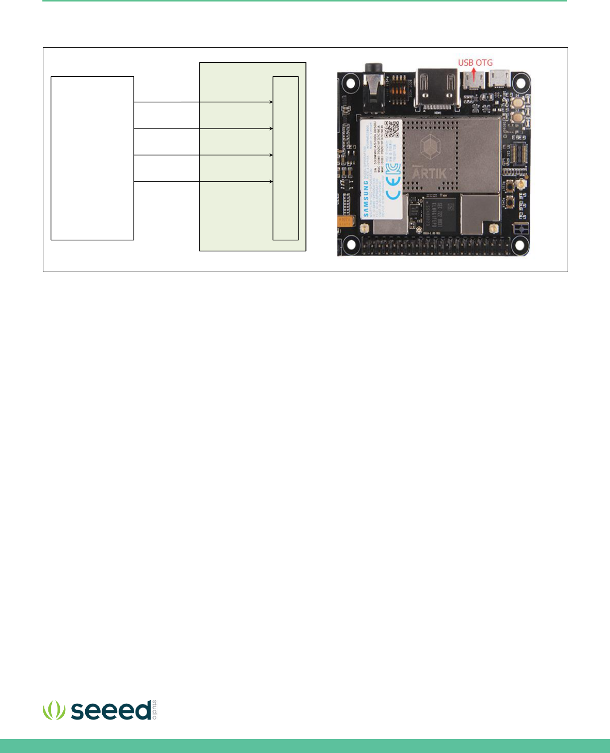
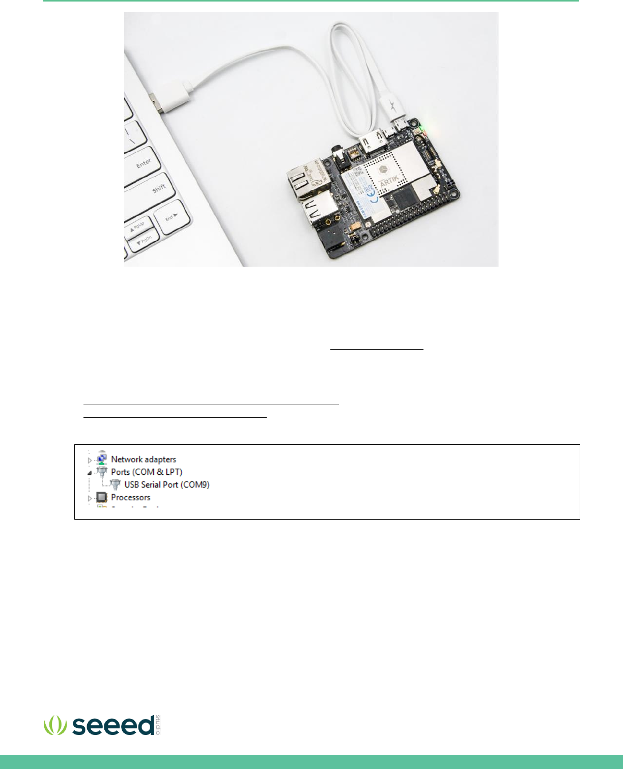
Eagleye 530s have a onboard USB to Serial converter. Just connect a
Micro USB cable to debug port. To use the serial USB cable you need to install the associated device driver. Figure 20
depicts
the USB serial cable and where it is hooked up to the Eagleye 530s.
Figure 19. Typical Linux® Serial Console
Seeed Technology Co., Ltd. Eagleye 530s User Guide
24
Figure 20. USB Cable hooked up to the Eagleye 530s
TERMINAL EMULATOR INSTALLATION
Setting up a connection with the ARTIK 530 Module can be done in a wired or wireless manner. Here we choose to install
PuTTY a free serial console. The software can be downloaded from
http://www.putty.org/
. Once downloaded go through the
following steps:
1. Open the device manager on the control panel.
2. When using a PC install the USB to Serial driver. The driver can be found at the following location:
(
http://www.ftdichip.com/Drivers/CDM/CDM21218_Setup.zip
). For other drivers please visit
(
http://www.ftdichip.com/Drivers/D2XX.htm
).
3. Check the COM port number on your PC when you connect the USB serial cable. In our case the COM port allocated
is COM9.
4. Set the PuTTY configuration as follows:
a. Set the “Serial line” as the COM port number found in step 3.
b. Set the COM speed to "115200".
c. Set the connection type to "Serial".
d. Save the session under ARTIK-Pro.
5. Select your saved session and click the “Open” button.
Seeed Technology Co., Ltd. Eagleye 530s User Guide
25
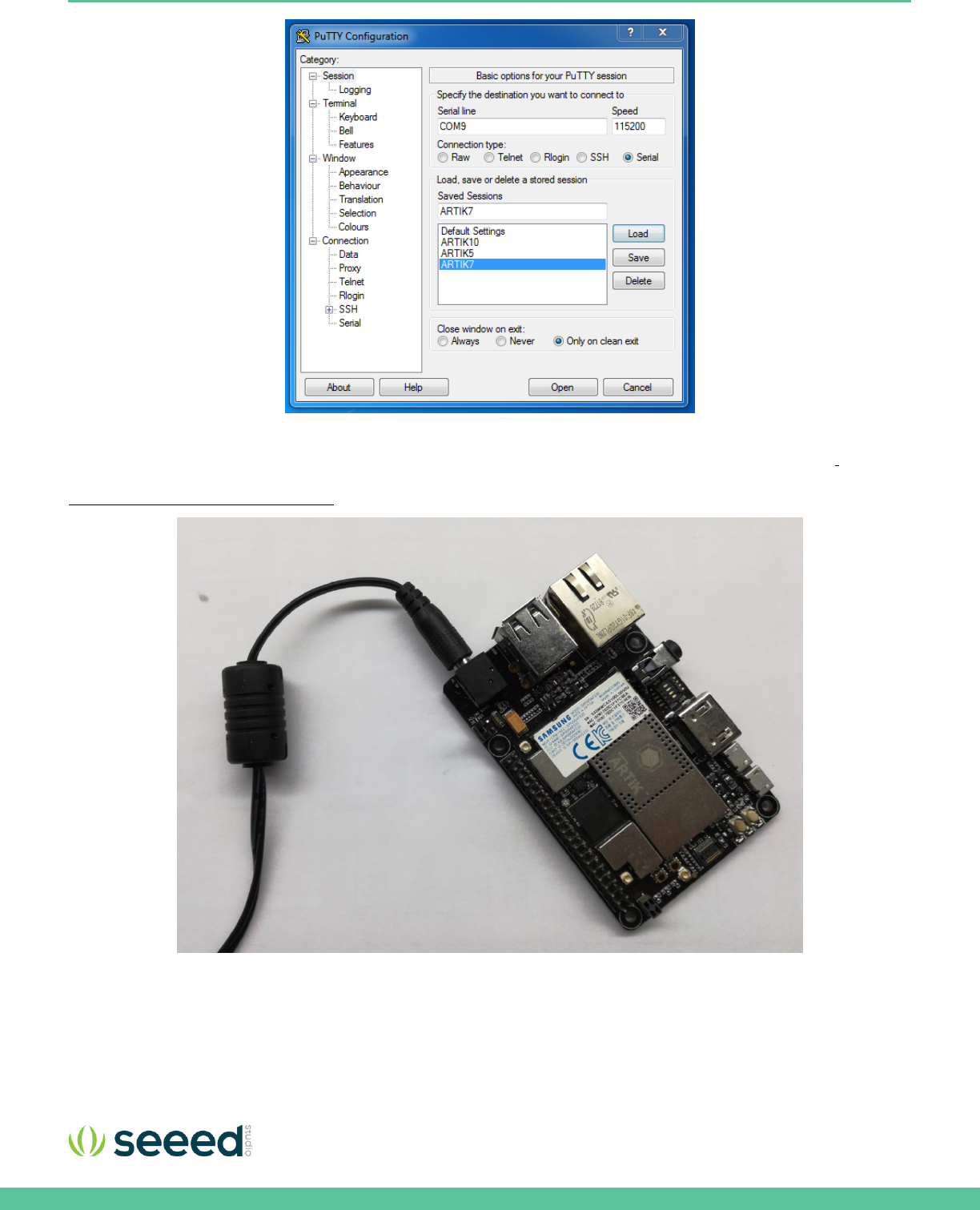
POWER ON THE EAGLEYE 530S
To power up the Eagleye 530s Development Environment you first have to connect the power adapter as shown in
Figure 21.
In addition make certain that the jumpers JP2 located on the Eagleye 530s are set in state with 3-4 position be connected
Configuration of External Power Source
section for details.
Figure 21. Connection Power adaptor with the Eagleye 530s
Seeed Technology Co., Ltd. Eagleye 530s User Guide
27
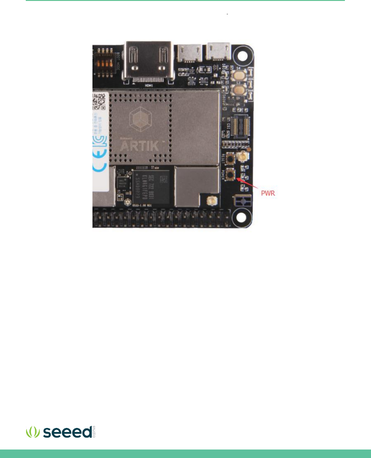
Once the power switch is turned on, push the power button (S1), as depicted in
Figure 23, for about 1 second. Once released
the booting process will start and you should see booting messages from your console, using the serial connection that you
previously established.
Figure 23. Power button location on the Eagleye 530s

Seeed Technology Co., Ltd. Eagleye 530s User Guide
28
FCC regulatory compliance information
This device complies with Part 15 of the FCC Rules. Operation is subject to the following two conditions: (1) this device may
not cause harmful interference, and (2) this device must accept any interference received, including interference that may
cause undesired operation.
Warning: changes or modifications not expressly approved by the party responsible for compliance could void the user’s
authority to operate the equipment.
End Device Labelling
Please notice that if the FCC identification number is not visible when the module is installed inside another device, then the
outside of the device into which the module is installed must also display a label referring to the enclosed module. This
exterior label can use wording such as the following: “Contains FCC ID:XXXXX” any similar wording that expresses the same
meaning may be used.
§ 15.19 Labelling requirements shall be complied on end user device. Integrator shall bear the following statement in a
conspicuous location on the device:
This device complies with part 15 of the FCC Rules. Operation is subject to the following two conditions: (1) This device may
not cause harmful interference, and (2) this device must accept any interference received, including interference that may
cause undesired operation.
For special device, please refer to § 15.19 (a)(5). For E-label approach, please refer to §2.935.
RF Exposure Compliance
This equipment complies with FCC radiation exposure limits set forth for an uncontrolled environment. This equipment
should be installed and operated with a minimum distance of 20cm between the radiator & your body. This transmitter must
not be co-located or operating in conjunction with any other antenna or transmitter.
Installation Notice
The module is limited to OEM installation ONLY. The OEM integrator is responsible for ensuring that the end-user has no
manual instruction to remove or install module.
The module is limited to installation in mobile application; A separate approval is required for all other operating
configurations, including portable configurations with respect to Part 2.1093 and difference antenna configurations.
FCC Part 15B Compliance of End Device
The OEM integrator is responsible for ensuring that the host product which is installed and operating with the module is in
compliant with Part 15B unintentional Radiator requirements, please note that For a Class B digital device or peripheral, the
instructions furnished the user manual of the end-user product shall include the following or similar statement, placed in a
prominent location in the text of the manual:
Note: This equipment has been tested and found to comply with the limits for a Class B digital device, pursuant to part 15 of
the FCC Rules. These limits are designed to provide reasonable protection against harmful interference in a residential
installation. This equipment generates, uses and can radiate radio frequency energy and, if not installed and used in
accordance with the instructions, may cause harmful interference to radio communications. However, there is no guarantee
that interference will not occur in a particular installation. If this equipment does cause harmful interference to radio or
television reception, which can be determined by turning the equipment off and on, the user is encouraged to try to correct
the interference by one or more of the following measures:
—Reorient or relocate the receiving antenna.
—Increase the separation between the equipment and receiver.
—Connect the equipment into an outlet on a circuit different from that to which the receiver is connected.
—Consult the dealer or an experienced radio/TV technician for help.

Seeed Technology Co., Ltd. Eagleye 530s User Guide
29
Industry Canada Regulatory Compliance Information
This device complies with Industry Canada license-exempt RSS standard(s). Operation is subject to the following two
conditions:
(1) this device may not cause interference, and (2) this device must accept any interference, including interference
that may cause undesired operation of the device.
Le présent appareil est conforme aux CNR d'Industrie Canada applicables aux appareils radio exempts de licence.
L'exploitation est autorisée aux deux conditions suivantes :
(1) l'appareil ne doit pas produire de brouillage, et (2) l'utilisateur de l'appareil doit accepter tout brouillage
radioélectrique subi, même si le brouillage est susceptible d'en compromettre le fonctionnement.
End Device Labelling
Please notice that if the IC identification number is not visible when the module is installed inside another device,
then the outside of the device into which the module is installed must also display a label referring to the enclosed
module. This exterior label can use wording such as the following: “Contains IC: 21046-EAGLEYE530S” any similar
wording that expresses the same meaning may be used.
L’étiquette d’homologation d’un module d’Innovation, Sciences et Développement économique Canada devra être
posée sur le produit hôte à un endroit bien en vue, en tout temps. En l’absence d’étiquette, le produit hôte doit
porter une étiquette sur laquelle figure le numéro d’homologation du module d’Innovation, Sciences et
Développement économique Canada, précédé du mot « contient », ou d’une formulation similaire allant dans le
même sens et qui va comme suit : Contient IC : 21046-EAGLEYE530S est le numéro d’homologation du module.
Notice to End Device Integrator
The host product integrator has to be aware not to provide information to the end user regarding how to install or
remove this RF module in the user’s manual of the end product which integrates this module. The end user manual
shall include all required regulatory information/warning as shown in this manual.
Le produit hôte intégrateur doit être conscient de ne pas fournir d'informations à l'utilisateur final sur la manière
d'installer ou de retirer ce module RF dans le manuel de l'utilisateur du produit final qui intègre ce module. Le
manuel de l'utilisateur final doit inclure toutes les informations / avertissements réglementaires requis, comme
indiqué dans ce manuel.
RF Exposure Compliance
This equipment complies with IC RSS-102 radiation exposure limits set forth for an uncontrolled environment. This
equipment should be installed and operated with minimum distance 20cm between the radiator and your body.
Cet équipement est conforme aux limites d'exposition aux radiations IC CNR-102 établies pour un environnement
non contrôlé. Cet équipement doit être installé et utilisé avec une distance minimale de 20 cm entre le radiateur et
votre corps.
The host product and all the separately certified modules therein shall jointly meet the radio frequency (RF)
exposure compliance requirements of RSS-102.
Le produit hôte, de même que tous les modules homologués séparément qu'il comporte, devront être
conjointement conformes aux exigences d'exposition aux radiofréquences du CNR-102.

Seeed Technology Co., Ltd. Eagleye 530s User Guide
30
5G Wi-Fi Use Notice
LE-LAN devices are restricted to indoor operation in the band 5150-5250 MHz to reduce the potential for harmful
interference to co-channel mobile satellite systems. However, original equipment manufacturer (OEM) devices,
which are installed in vehicles by vehicles manufacturers, are permitted.
Les appareils LE-LAN sont limités à un fonctionnement en intérieur dans la bande 5150-5250 MHz afin de réduire le
risque de brouillage préjudiciable aux systèmes mobiles par satellite dans le même canal. Cependant, les dispositifs
du fabricant d'équipement d'origine (OEM), qui sont installés dans les véhicules par les fabricants de véhicules, sont
autorisés.
the maximum antenna gain permitted for devices in the band 5725-5825 MHz shall comply with the e.i.r.p. limits
specified for point-to-point and non point-to-point operation as appropriate.
le gain maximal d’antenne permis (pour les dispositifs utilisant la bande 5 725-5 825 MHz) doit se conformer à la
limite de p.i.r.e. spécifiée pour l’exploitation point à point et non point à point, selon le cas.
Manufacturer Information
Company Name: Seeed Technology Co., Ltd.
Company Address: 1F, Tower B, Building 2, Shanshui Building, NanshanYungu Innovation Industry Park,
Liuxian Ave, Nanshan District, Shenzhen, Guangdong, P.R.C.
Zip:518055
Tel:0086 755 86524359
Fax:0086 755 26978025
CE Doc
Hereby, Seeed Technology Co., Ltd. declares that the radio equipment type [Eagleye 530s] is in compliance with Directive
2014/53/EU.The full text of the EU declaration of conformity is available at the following internet address:
https://www.seeedstudio.com/Eagleye-530s-p-3035.html