Semiconductor 2006001 Bluetooth Module User Manual
Taiwan Semiconductor Co. Ltd. Bluetooth Module
UserManual.wiki
>
Semiconductor
>
2006001 User Manual
Manual
Navigation menu
Upload a User Manual
Namespaces
Wiki Guide
HTML
PDF
Info
Views
User Manual
Discussion / Help
Navigation
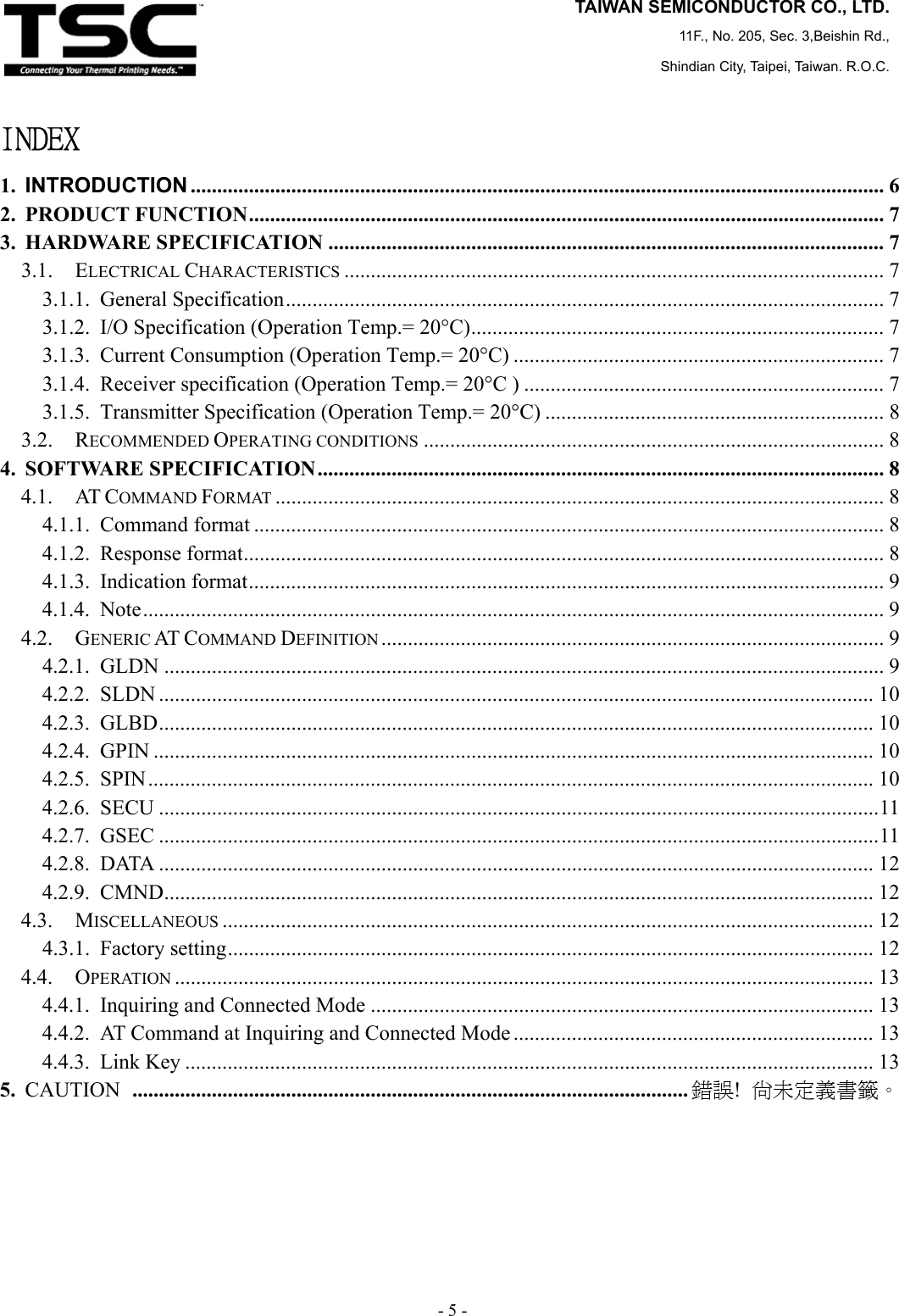
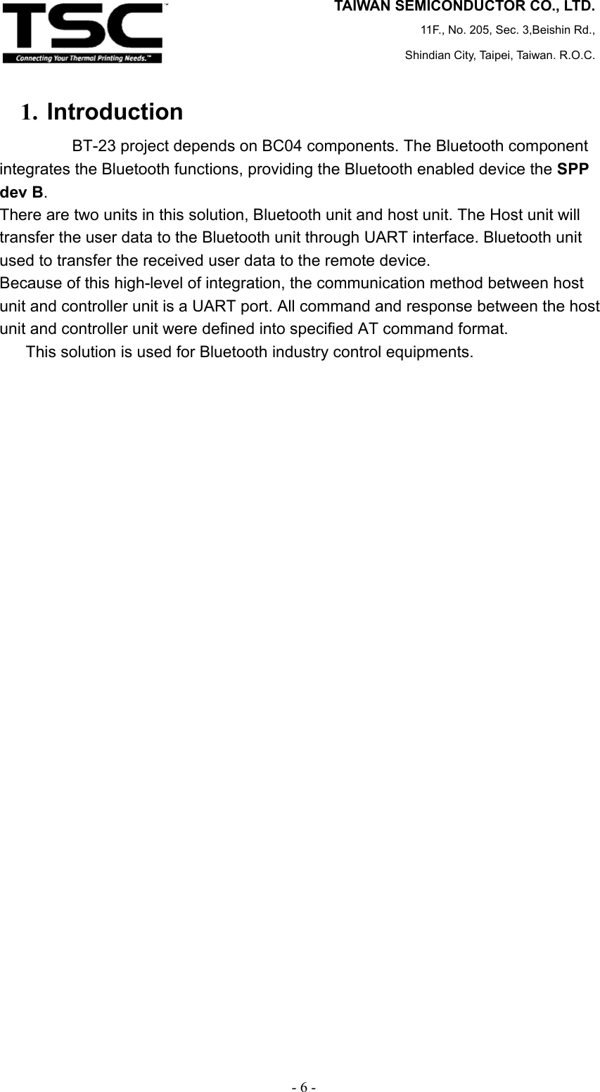
![TAIWAN SEMICONDUCTOR CO., LTD. 11F., No. 205, Sec. 3,Beishin Rd., Shindian City, Taipei, Taiwan. R.O.C. - 8 - 3.1.5. Transmitter Specification (Operation Temp.= 20°C) Description Min. Typ. Max. UnitMaximum RF transmit power - 1 - dBmRF power variation over temperature range with compensation disabled - 2 - dBmRF power control range 25 35 - dB 3.2. Recommended Operating conditions Description Min. Typ Max. Unit Operating temperature -20 +70 °C Supply voltage: 3.3 Volts 4. Software Specification 4.1. AT Command Format 4.1.1. Command format <at-command-object>::={ <at-command-header><SPACE> <at-command-body><SPACE> [<at-command-parameter>[COMMA]]* <CR> } <at-command-header>::=AT+BT <at-command-body>::=’character set, upper case, length = 4 <at-command-parameter>::=’ number set and character set, be separated by comma, the last parameter need not comma-tailed’ 4.1.2. Response format <at-response-object>::={ <at-response-header><SPACE> <at-response-body><SPACE> [<at-response-parameter><COMMA>]* <CR> } <at-response-header>::=AT-BT <at-response-body>::=’character set, upper case, length = 4’ <at-response-parameter>::=’number set and character set, be separated by comma, the last parameter need not comma-tailed’](https://usermanual.wiki/Semiconductor/2006001/User-Guide-690984-Page-6.png)
![TAIWAN SEMICONDUCTOR CO., LTD. 11F., No. 205, Sec. 3,Beishin Rd., Shindian City, Taipei, Taiwan. R.O.C. - 9 - 4.1.3. Indication format <at-indication-object>::={ <at-indication-header><SPACE> <at-indication-body><SPACE> [<at-indication-parameter><COMMA>]* <CR> } <at-indication-header>::=AT-BT <at-indication-body>::=’character set, upper case, length = 4’ <at-indication-parameter>::=’ number set and character set, be seperated by comma, the last parameter need not comma-tailed’ 4.1.4. Note Chapter after 3 details the each of the Bluetooth component AT commands, response and indication, including a brief description of behavior, syntax of the command, context of the command, and types of responses. Some responses will not be “immediate”. Where applicable, these will be noted and will include an approximate delay before response. For commands with optional parameters, all possible forms will be listed under the syntax subsection. Note that a full piece of AT command, AT response or AT indication must be tailed with “\r” (0x0d). 4.2. Generic AT Command Definition This chapter details the generic AT commands, response and indication, including a brief description of behavior, syntax of the command, context of the command, and types of responses. These commands are profile independent. 4.2.1. GLDN The GLDN command is used to get the local device name. Syntax AT+BT GLDN Response If the command succeeded, the response is: AT-BT GLDN 1,[name] If the command failed, the response is:](https://usermanual.wiki/Semiconductor/2006001/User-Guide-690984-Page-7.png)
![TAIWAN SEMICONDUCTOR CO., LTD. 11F., No. 205, Sec. 3,Beishin Rd., Shindian City, Taipei, Taiwan. R.O.C. - 10 - AT-BT GLDN 0,0 4.2.2. SLDN The SLDN command is used to set the local device name. Syntax AT+BT SLDN [name] Response If the command succeeded, the response is: AT-BT SLDN 1 If the command failed, the response is: AT-BT SLDN 0 Note: Maximum device name length is 16. 4.2.3. GLBD The GLBD command is used to get the local Bluetooth device address. Syntax AT+BT GLBD Response If the command succeeded, the response is: AT-BT GLBD 1,[bd] If the command failed, the response is: AT-BT GLBD 0,0 4.2.4. GPIN The GPN command is used to get the local fixed PIN code. Syntax AT+BT GPIN Response If the command succeeded, the response is: AT-BT GPIN 1,[pin] If the command failed, the response is: AT-BT GPIN 0,0 4.2.5. SPIN The SPIN command is used to set the fixed PIN code.](https://usermanual.wiki/Semiconductor/2006001/User-Guide-690984-Page-8.png)
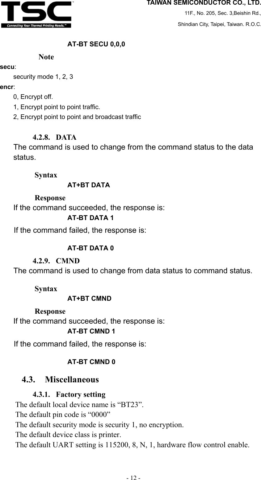
![TAIWAN SEMICONDUCTOR CO., LTD. 11F., No. 205, Sec. 3,Beishin Rd., Shindian City, Taipei, Taiwan. R.O.C. - 11 - Syntax AT+BT SPIN [pin] Response If the command succeeded, the response is: AT-BT SPIN 1 If the command failed, the response is: AT-BT SPIN 0 Note If the bd is 0, then used to response to the current pin code indication. 4.2.6. SECU The SECU command is used to set the security mode and encryption mode. Syntax AT+BT SECU [par1],[par2] par1: security mode 1, 2, 3 par2: 0, Encrypt off. 1, Encrypt point to point traffic. 2, Encrypt point to point and broadcast traffic Response If the command succeeded, the response is: AT-BT SECU 1 If the command failed, the response is: AT-BT SECU 0 Note It is recommended that the security mode be changed only when the system is not in the process of creating or accepting connections. 4.2.7. GSEC The GSEC command is used to get the security mode and encryption mode. Syntax AT+BT GECU Response If the command succeeded, the response is: AT-BT SECU 1, [secu],[encr] If the command failed, the response is:](https://usermanual.wiki/Semiconductor/2006001/User-Guide-690984-Page-9.png)