Senao Co 2511AP2PLUS Wireless LAN Access Point User Manual SL 2511AP2 User Guide v1 04
Senao International Co Ltd Wireless LAN Access Point SL 2511AP2 User Guide v1 04
Senao Co >
Manual
0
SENAO
SL-2511AP2 PLUS
Wireless LAN Access Point
User’s Guide

1
1 FEATURES.................................................................................................................................2
2 HARDWARE CONFIGURATION ..........................................................................................2
2.1 HARDWARE CONFIGURATION ................................................................................................2
2.2 HARDWARE INSTALLATION....................................................................................................2
3 INITIAL SOFTWARE INSTALLATION AND CONFIGURATION ..................................3
4 CONFIGURING THE ACCESS POINT THROUGH WEB BROWSER...........................5
4.1 SYSTEM SETTING ..................................................................................................................6
4.1.1 System Time..................................................................................................................7
4.1.2 Administrator Setting ...................................................................................................7
4.1.3 Firmware Upgrade.......................................................................................................8
4.1.4 Configuration Tools .....................................................................................................9
4.1.5 Status.......................................................................................................................... 11
4.1.6 Reset...........................................................................................................................12
4.2 LAN SETTING.....................................................................................................................13
4.2.1 LAN Settings...............................................................................................................13
4.2.2 DHCP Client Lists .....................................................................................................14
4.2.3 DNS Settings ..............................................................................................................15
4.3 FILTERING SETTING.............................................................................................................15
4.3.1 MAC Filtering............................................................................................................15
4.3.2 IP Filtering.................................................................................................................16
4.4 WIRELESS SETTING .............................................................................................................16
4.4.1 General ......................................................................................................................17
4.4.2 Enhanced Features.....................................................................................................19
4.4.3 Associated Clients......................................................................................................20
4.5 SNMP.................................................................................................................................20
4.5.1 SNMP Community......................................................................................................20
4.5.2 SNMP Trap.................................................................................................................21
5 CONFIGURING THE ACCESS POINT THROUGH TELNET .......................................22
5.1 ENTER THE TELNET SESSION ...............................................................................................22
5.2 COMMAND LINE FOR TELNET DAEMON...............................................................................24
5.3 CONFIGURING WIRELESS LAN THROUGH TELNET .............................................................32
5.4 CONFIGURING LAN THROUGH TELNET ..............................................................................37
5.5 CONFIGURING SYSTEM THROUGH TELNET ..........................................................................39
5.6 CONFIGURING FILTERING THROUGH TELNET ......................................................................43
5.7 CONFIGURING SNMP THROUGH TELNET............................................................................45

2
5.8 UPGRADING FIRMWARE THROUGH TELNET .........................................................................48
6 CHANGE HISTORY...............................................................................................................51
7 STATEMENT ...........................................................................................................................52
1 Features
z Fully interoperable with IEEE 802.11b compliant products.
z High-Speed data transfer rate up to 11Mbps.
z 64-bit and 128-bit WEP Encryption.
z MAC Address and TCP/UDP/IP filtering.
z Web-Based Network Manager/Telnet for Configuring and Managing Your Access Points.
z SNMP MIB I and MIB II supported.
z Capable of acting as a DHCP Server.
z Remote Management supported.
z Firmware Upgrade via WEB/TFTP
2 Hardware Configuration
2.1 Hardware Configuration
1. RJ-45 Ethernet connector
Provides 10/100 Mbps connectivity to a wired Ethernet LAN.
2. Reset Button
By pressing this button for over 3 seconds, the AP will be reset with factory default
configuration.
3. Power Supply connector
It is for connecting to the power adapter.
2.2 Hardware Installation
1. Configure your notebook or PC with Wireless LAN card.
2. For Wired LAN, connect your PCs’ Ethernet port to any AP’s LAN port by an Ethernet cable.
3
3. For WLAN, locate the AP to a proper position.
4. Plug the power cord into a power outlet.
3 Initial Software Installation and Configuration
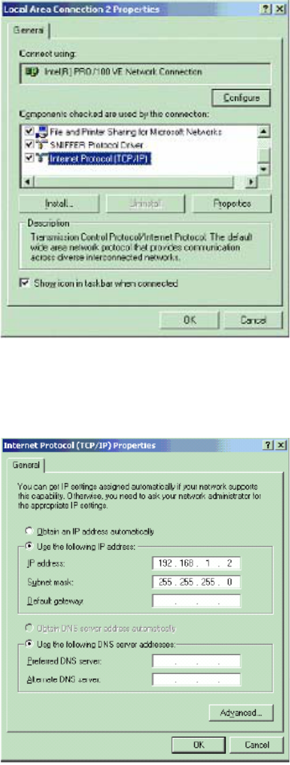
1. Change the TCP/IP setting of your managing computer. Select the TCP/IP line that has been
associated to your network card. Click the Properties button.
2. Make sure the IP address of your computer and the AP are in the same subnet. The default IP
address of the Access Point is 192.168.1.1 and the default subnet mask is 255.255.255.0.
4
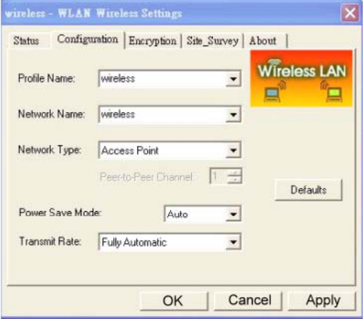
3. For WLAN, open the WLAN client utility. Click Configuration tab. Type default SSID (default
SSID: wireless) in the Network Name field. Choose “Access Point” for Network Type, then
click OK button.
Note: the default channel is 6.
5
4 Configuring the Access Point through Web
Browser
The Access Point can be configured through your web browser with the Web-Based Utility.
Open your web browser and type the default IP address of the AP in the address field (default IP:
192.168.1.1) and press Enter. Make sure the IP address of AP and your computer are in the same
subnet.
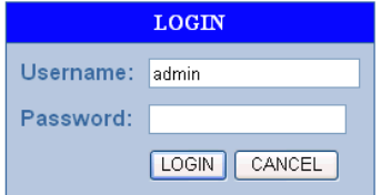
After the connection is established, you will see the User Login page as shown below. Leave
the password field blank when the first time you open the Web-Based utility. You can change the
password on the “Administrator settings” page.
The system will be time out after idling about 1 minute. You have to login again to re-enter the
main setting page. You can change the idle time out period on the “Administrator settings” page.
On any page, you can click HELP to obtain more descriptions and explanations. To clear any
values you’ve entered on any page, click CANCEL and re-enter information.
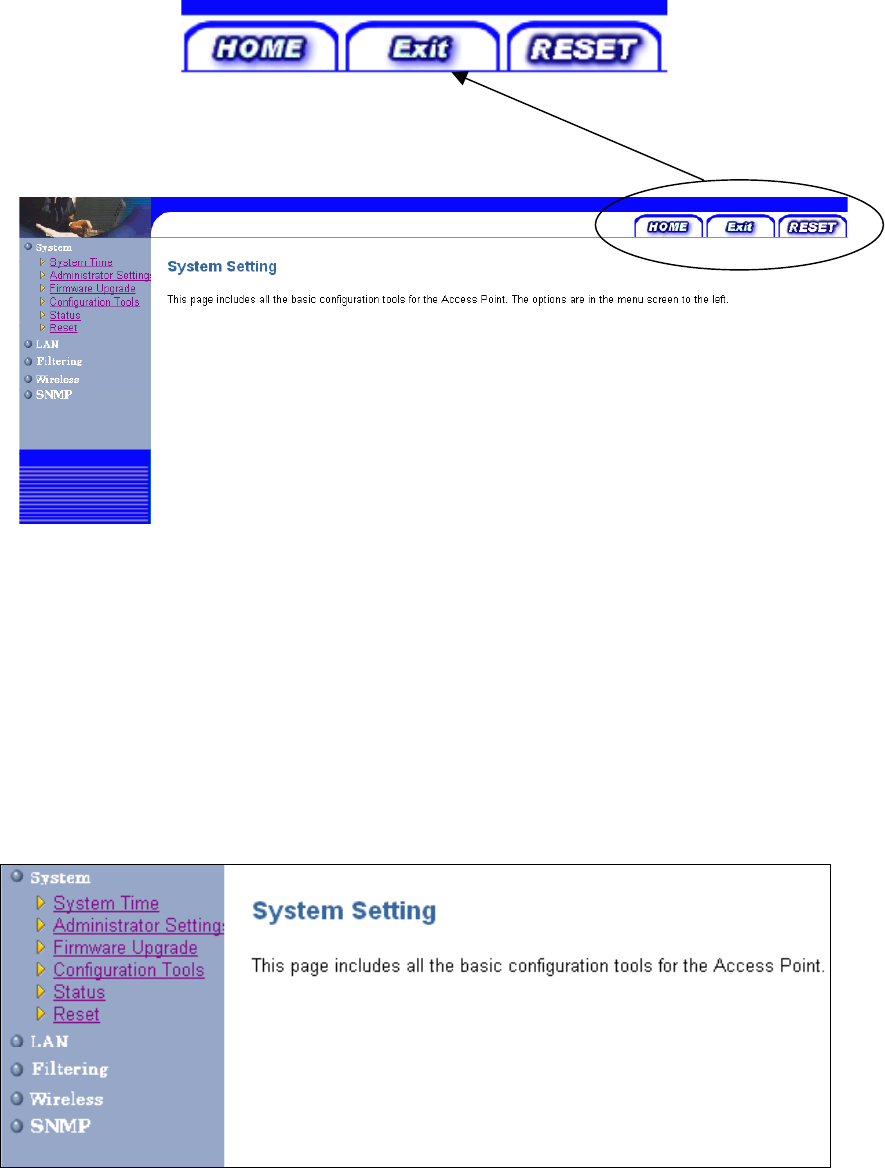
There are three tabs on the upper right-corner of each page. To go back to the main setting
page, press HOME tab. To log out of the web management, press EXIT tab. To complete any
change you have made, press RESET tab after clicking APPLY button.
6
4.1 System Setting
The system setting contains all basic configuration of the Access Point. It includes System
Time, Administrator Setting, Firmware Upgrade, Configuration Tools, Status, and Reset.
7
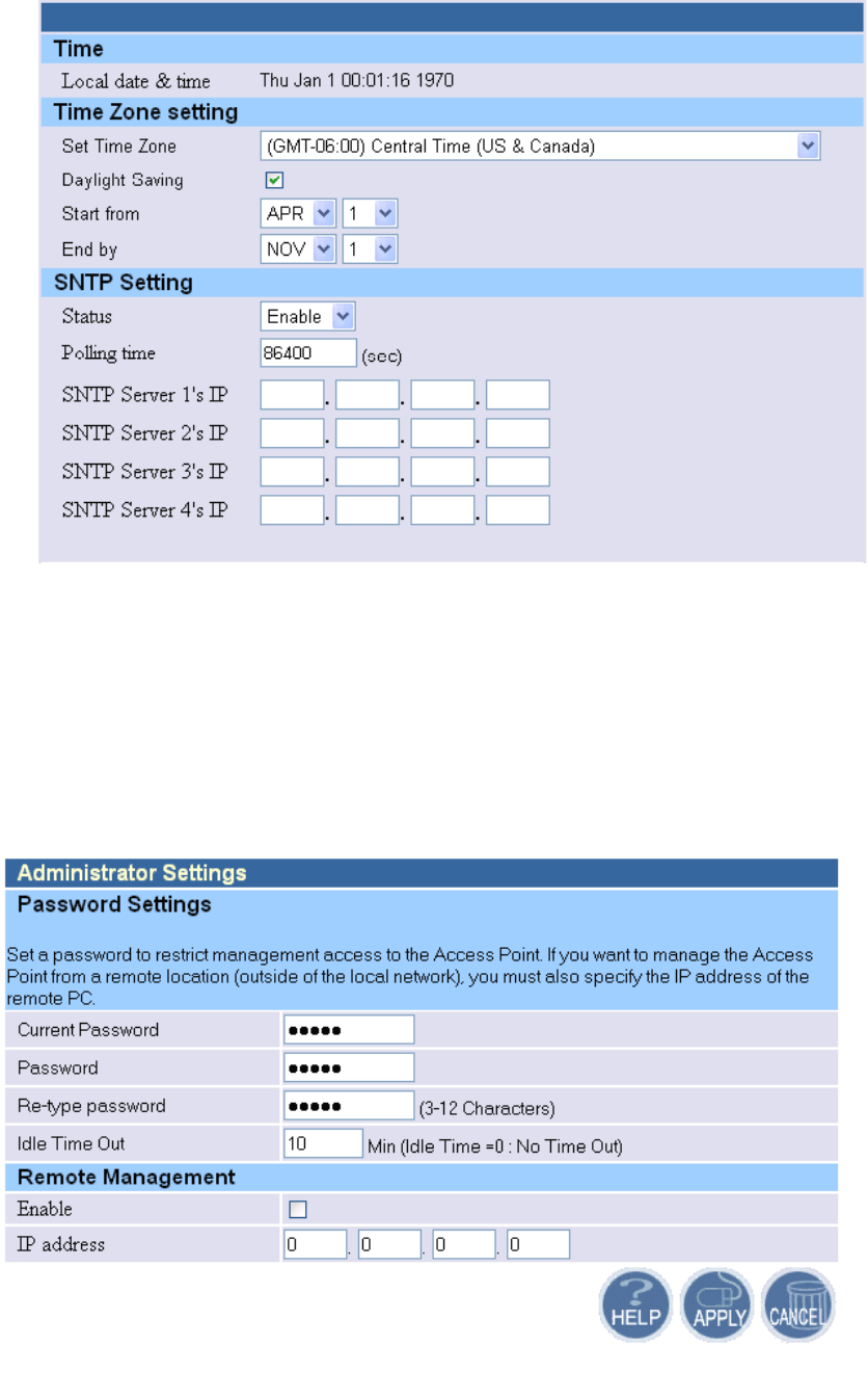
4.1.1 System Time
Connecting to a Simple Network Time Protocol (SNTP) server allows the AP to synchronize
the system clock to the global internet. The synchronizes clock in the AP is used to control client
filtering. The polling time is the time period that the AP sends requests for the correct time. Note
that the polling time can not be less than 3600 sec. Click APPLY to complete your change.
4.1.2 Administrator Setting
Set a password to restrict management access to the Access Point. If you want to manage the
Access Point from a remote location (outside of the local network), you must also specify the IP
8
address of the remote PC.
Password Settings:
To change your password, enter your current password in the “Current Password” box. Enter
new password in the “Password” box. Enter it again in the “Re-type password” box to confirm it.
Click APPLY to complete your change.
The “idle Time Out” is the amount of time of inactivity before the Access Point will
automatically close the Administrator session. Set this to zero to disable it.
Remote Management:
By default, management access is only available to users on your local network. However, you
can also manage the Access Point from a remote host. Just check the Enable check box and enter
the IP address of an administrator to this screen.
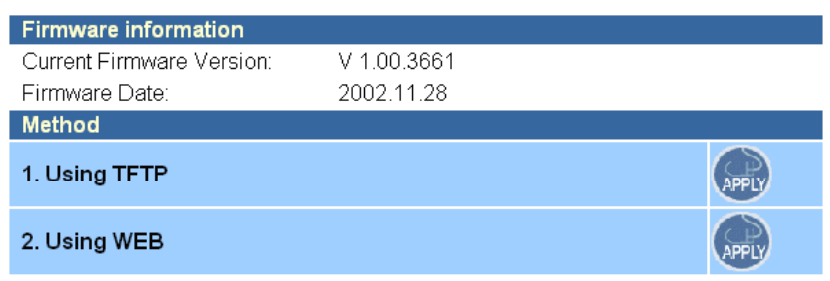
4.1.3 Firmware Upgrade
The firmware information is displayed on this page. You can find firmware version and
firmware date here. There are two ways to upgrade the firmware: “Using TFTP” and “Using WEB”.
Click APPLY to choose the one you want.
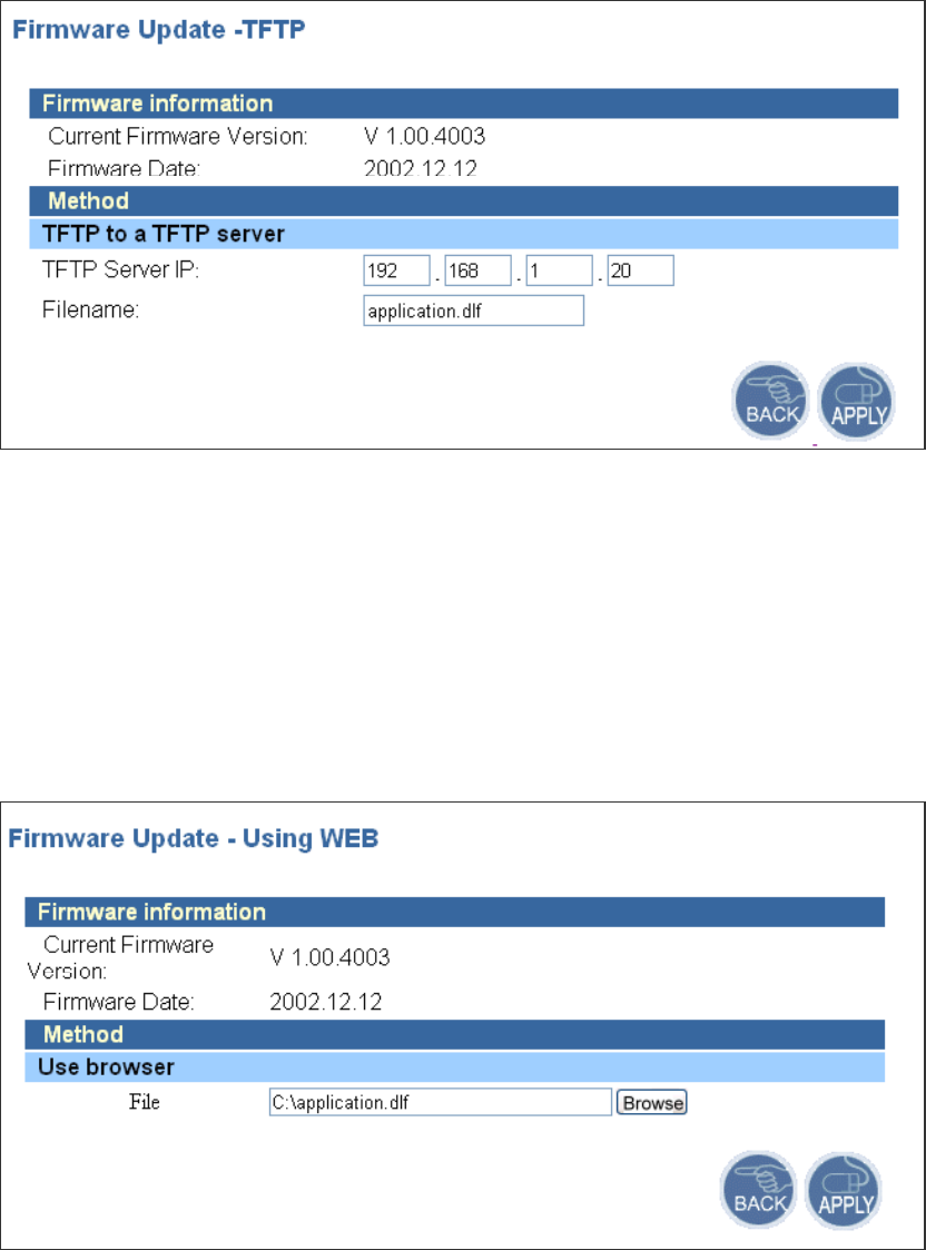
z Using TFTP
On the managed computer, run the TFTP Server utility. And specify the folder in which the
firmware file resides. After running the TFTP server, enter the TFTP server IP and the filename on
the following page. Click on APPLY to complete your change.
9
z Using WEB
Type the correct firmware file path and file name on the File field. You can click Browse to
select the file location. Click on APPLY to complete your change.
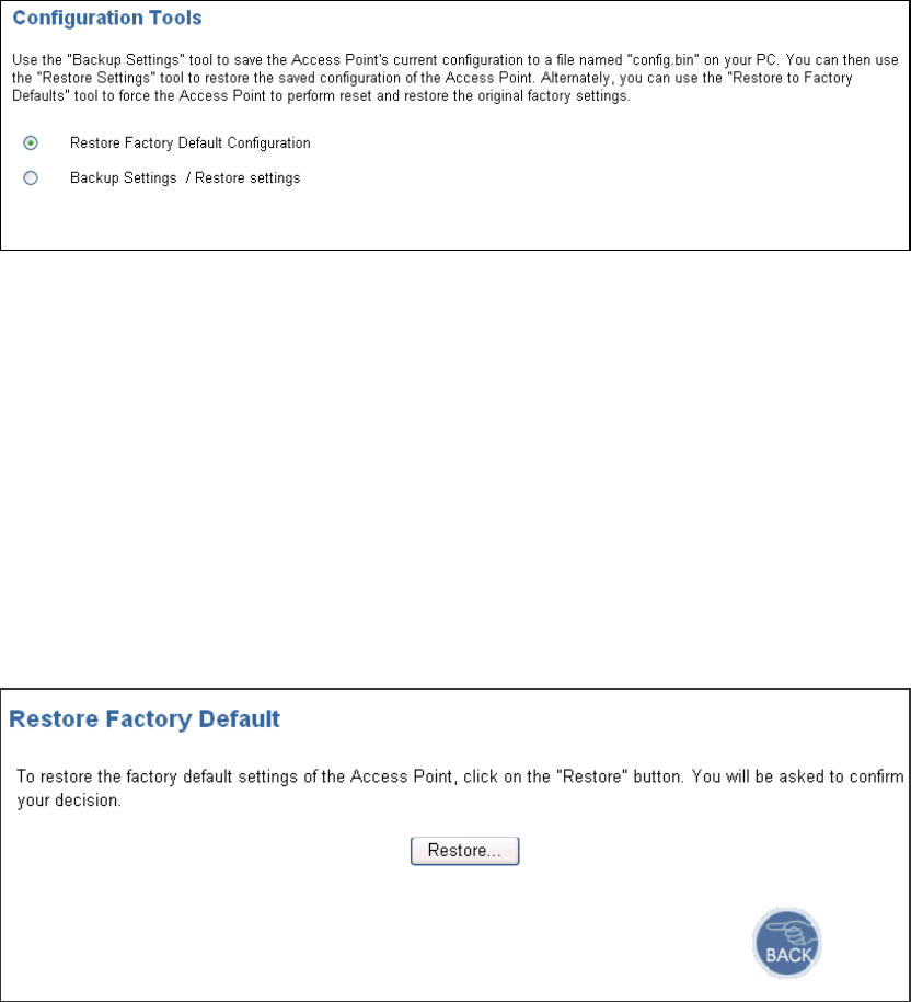
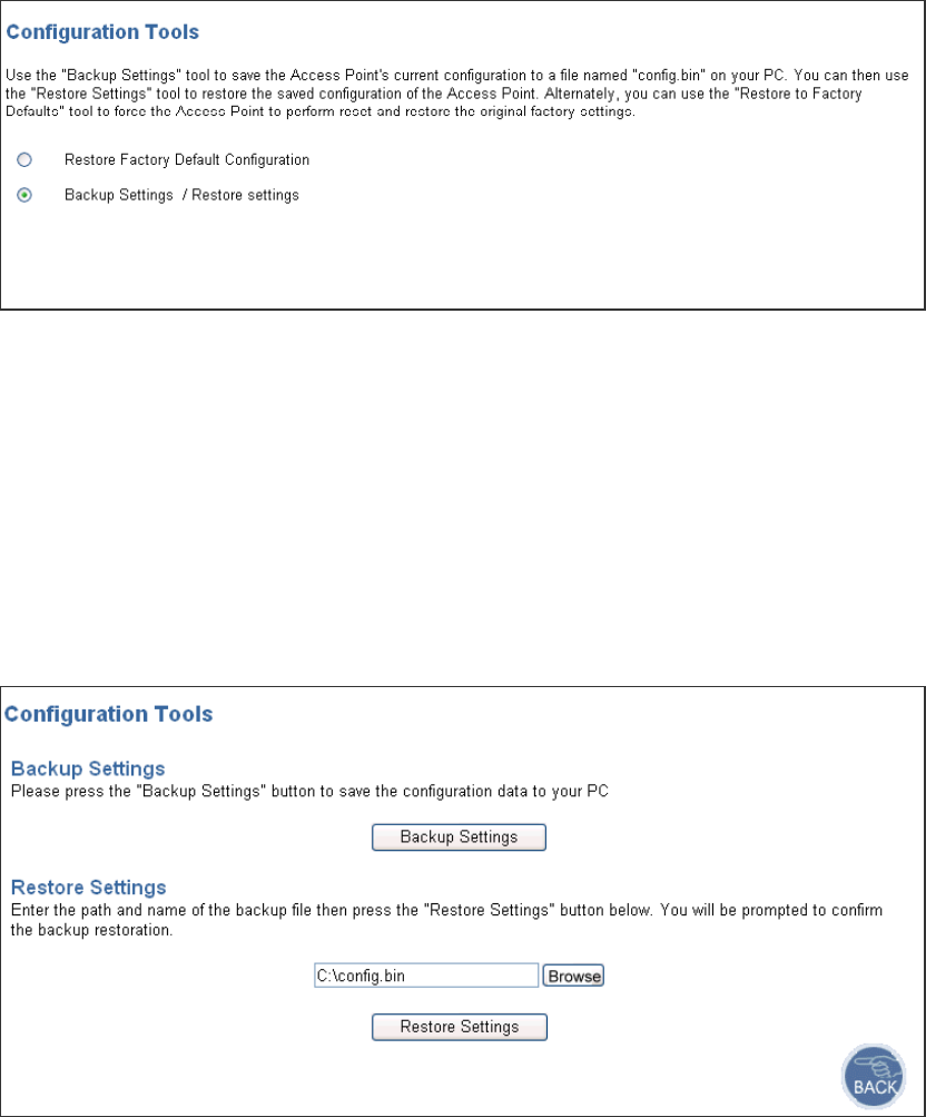
4.1.4 Configuration Tools
This tool can backup or restore the AP’s configuration. It can also restore the original factory
default settings.
z Restore Factory default configuration:
10
(1) Check the “Restore Factory Default Configuration” radio button then click APPLY.
(2) Click Restore button to force the Access Point to perform reset and restore the original
factory settings.
z Backup Setting/Restore Settings:
(1) Check the “Backup Settings/Restore Settings” radio button and click APPLY.
11
(2) To save the Access Point's current configuration to a file named "config.bin" on your PC, click
Backup Settings button.
(3) To restore configuration, you can use the "Restore Settings" tool to restore the saved
configuration of the Access Point.
(4) Enter the path and file name then click Restore Settings button. You can also click Browse to
locate and select the previously saved backup file.
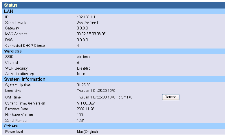
4.1.5 Status
12
The Status window displays current information and settings for your AP. It has four main
parts - LAN, Wireless, System Information, and Others.
For LAN, it displays AP’s IP address, MAC address, Subnet Mask, and Gateway. It also
displays the IP address of the DNS and the number of clients connected by DHCP server.
For Wireless, it displays SSID, Channel, WEP security status, and Authentication type.
For System Information, it displays system time, firmware version, firmware date, hardware
version, and serial number.
For Others, it displays the power level of the AP.
You can obtain the most up-to-date information by pressing the “Refresh” button.
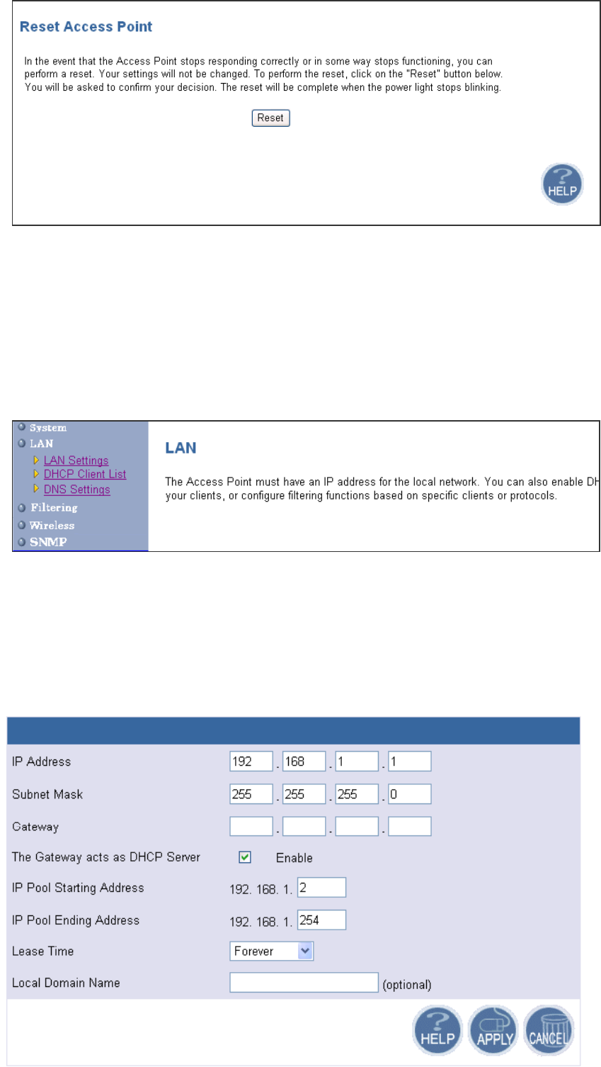
4.1.6 Reset
In the event that the Access Point stops responding correctly or in some way stops functioning,
you can perform a reset. Your settings will not be changed. To perform the reset, click on the Reset
button below. You will be asked to confirm your decision. The reset completes when the power
light stops blinking.
13
4.2 LAN Setting
The Access Point must have an IP address for the local network. You can enable DHCP service
for dynamic IP address allocation to your clients, or configure filtering functions based on specific
clients or protocols.
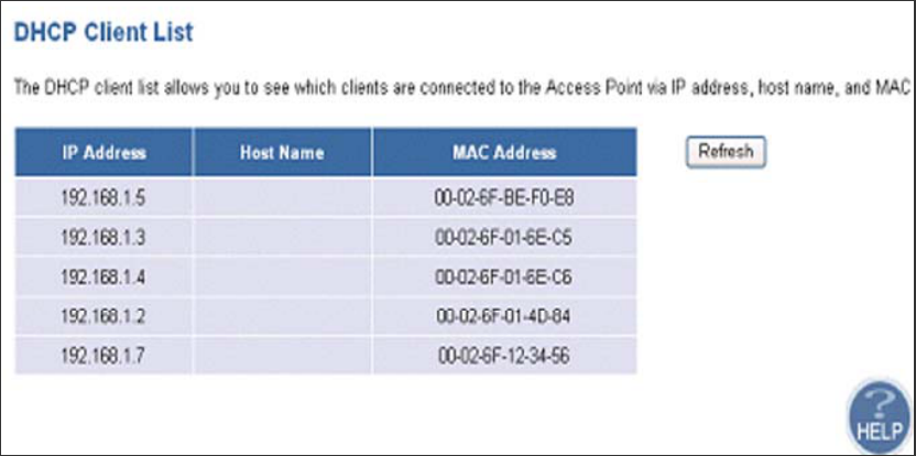
4.2.1 LAN Settings
You can change the basic settings of AP here, including IP address, Subnet mask, Gateway, IP
Pool Address, Lease Time, and Local Domain Name. Click APPLY to complete your change.
14
(1) IP Address: The IP address of the AP. You should have a unique IP address to your
network. The default value is 192.168.1.1.
(2) Subnet Mask: The Subnet Mask of your Access Point. The default value is 255.255.255.0.
(3) Gateway: It indicated the Network’s Gateway. It’s optional.
(4) The Gateway acts as the DHCP Server: By default, the AP can function as a DHCP server.
The AP can automatically assign an IP address to a client. To disable this function, clear
the “Enable” check box.
(5) IP Pool Starting Address & IP Pool Ending Address: The first and the last address in the
IP address pool.
(6) Lease Time: The period client can have the IP address assigned by DHCP server.
(7) Local Domain Name: It’s optional.
4.2.2 DHCP Client Lists
This page lists clients that are connected to the Access Point via IP address, host name, and
MAC address. You can click Refresh button to obtain most up-to-date information.
Note: The DHCP server only serves wireless clients. So LAN users cannot get IP address through
DHCP server.
15
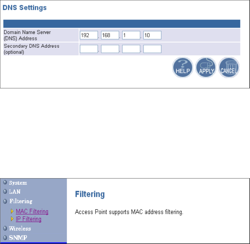
4.2.3 DNS Settings
Domain Name Servers are used to map an IP address to the equivalent domain name. Your ISP
should provide the IP address for one or more domain name servers. The Access Point can be a
DNS relay to send clients’ request to the Domain Name Server. You can do a DNS lookup to find
the IP address of some specific servers. Click APPLY to complete your change.
4.3 Filtering Setting
The Access Point provides filtering function via MAC address or IP address for wireless
interface.
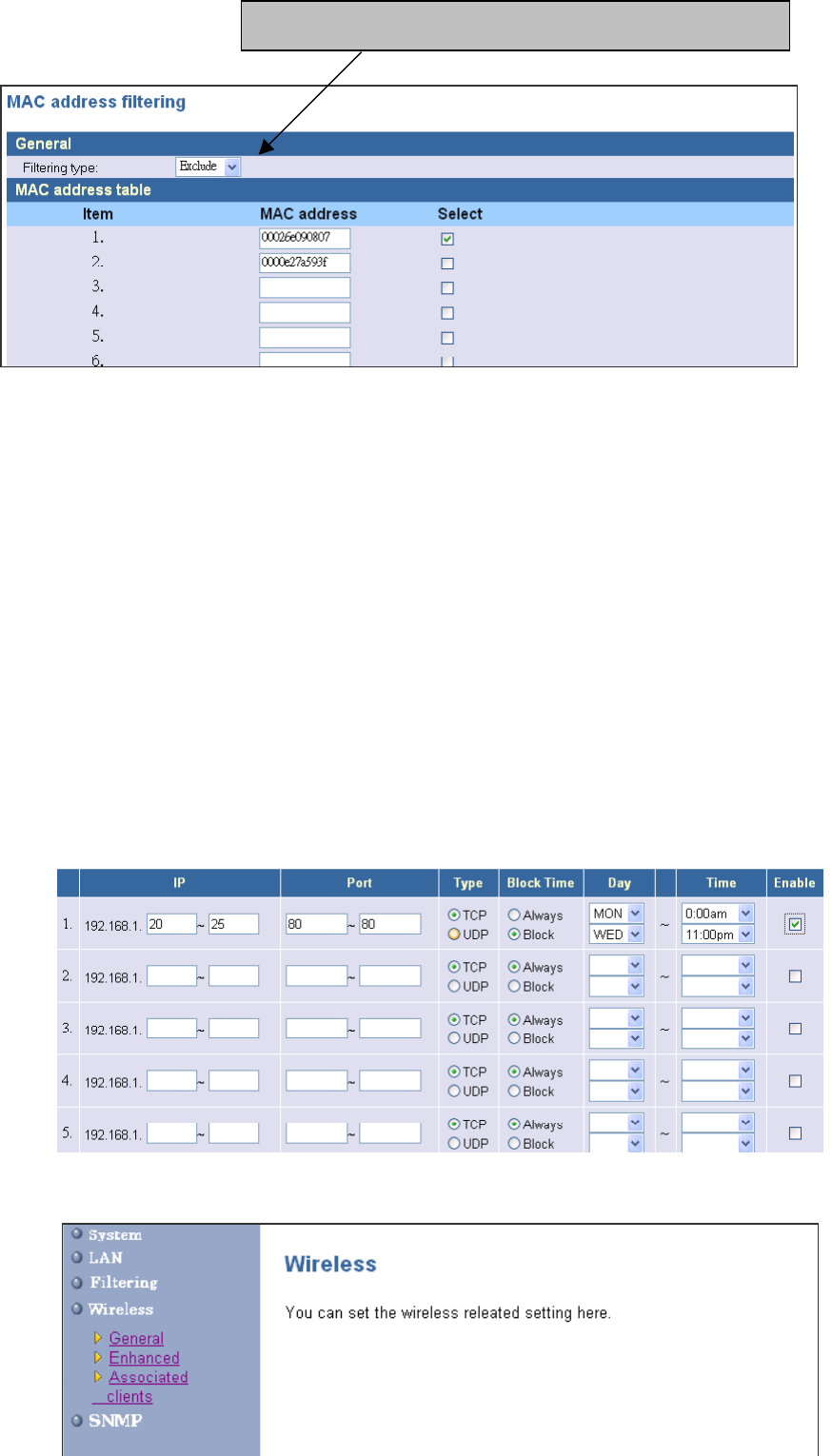
4.3.1 MAC Filtering
The maximum number of items is 64. Check the select check box to include or exclude
corresponding items. The clients whose MAC addresses listed in the “MAC address table” cannot
get associations to the AP while the “Filtering type” is chosen to “Include”. On the other hand, only
those clients’ with MAC addresses listed in the “Exclude” filtering list can associate to the AP. The
MAC address filtering function can be disabled by choosing the “Filtering type” to “Disable”. Click
APPLY to complete your change.
16
4.3.2 IP Filtering
You can block certain client PCs accessing the internet based on time. IP Filtering can filter the
packets sent from clients. For example, you can ban WEB browsing by setting the port to “80”.
Remember to select the Check box in the “Enable”. Click APPLY to complete your change.
4.4 Wireless Setting
There are three filtering type: Include, Exclude, and Disable
17
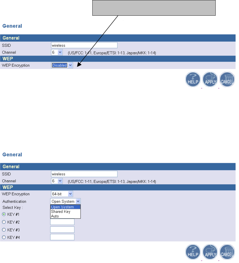
4.4.1 General
In this window you can make changes to the default wireless settings. For communicating, all
computers on the network must be within the same IP Address range, and have the same settings for
the Radio channel and SSID. If you don’t want to utilize WEP Encryption, select “Disable” to
disable this function.
(1) SSID: The SSID is a unique name shared among all points in your wireless network. The
SSID must be identical for all points in the network. It is case sensitive and must not
exceed 32 characters.
(2) Channel: The channel shared by all wireless devices. The range of channel is 1~14.
(3) WEP: Short for Wired Equivalent Privacy, a security protocol for wireless local area
networks (WLANs) defined in the 802.11b standard. WEP is designed to provide the same
level of security as that of a wired LAN. Select Disabled to disable this function.
There are two WEP Encryption key length: 64-bit(10 hex digits) and 128 bit(26
Select “Disable” to disable WEP Encryption

18
hex digits). For Authentication type, you can choose between Open System1, Shared Key2 ,
and Auto3. All station on your network must use the same authentication type. Check your
wireless card’s documentation to see what type to use.
1 Open System - An open system allows any client to authenticate as long as it conforms to any MAC address filter
policies that may have been set. All authentication packets are transmitted without encryption.
2 Shared Key - when both the sender and the receiver share a secret key. When "Shared Key" is checked, the AP sends
an unencrypted challenge text string to any device attempting to communicate with the AP. The device requesting
authentication encrypts the challenge text and sends it back to the access point. If the challenge text is encrypted
correctly, the access point allows the requesting device to authenticate.
3 Auto – No matter the authentication packets with encryption or not, the access point allows the requesting device to
authenticate.
19
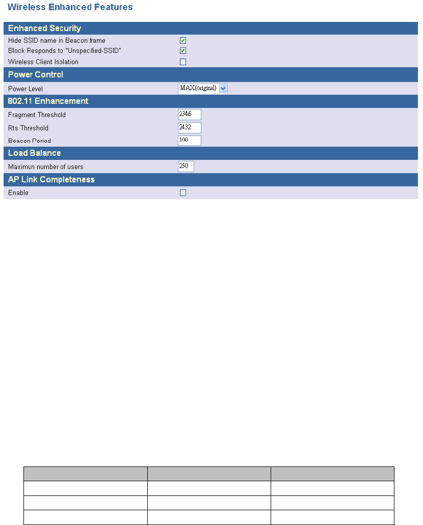
4.4.2 Enhanced Features
(1) Enhanced Security:
1. Hide SSID name in Beacon frame: By selecting this function , AP will not broadcast it’s
SSID in the beacon frame.
2. Block Responds to “Unspecified-SSID”: By selecting this function , AP will not respond
wireless client’s association requests using “ANY” as the AP’s SSID.
3. Wireless Client isolation: By selecting this function , the AP will not forward uni-cast,
multi-cast and broadcast packets to clients sent from any client.
(2) Power Control: If you select MAX(Original), then the power is the same as the network
card’s power.
(3) 802.11 Enhancement: The setting is listed below.
Field Ranges Default value
Fragment Threshold 256 - 2346 (bytes) 2346
RTS Threshold 0 – 3000 (ms) 2432
Beacon Period Up to 4095 ms 4095
(4) Load Balance: This is the maximum number of users that can associate to this AP. The new
client’s association will not be accepted when the number of associated clients reaches this
number.
(5) AP Link Completeness: If this function is enabled, the AP will disassociated all associated
20
clients and ban all new association requested when the LAN Ethernet port gets no signals (e.g. it
is unplugged)..
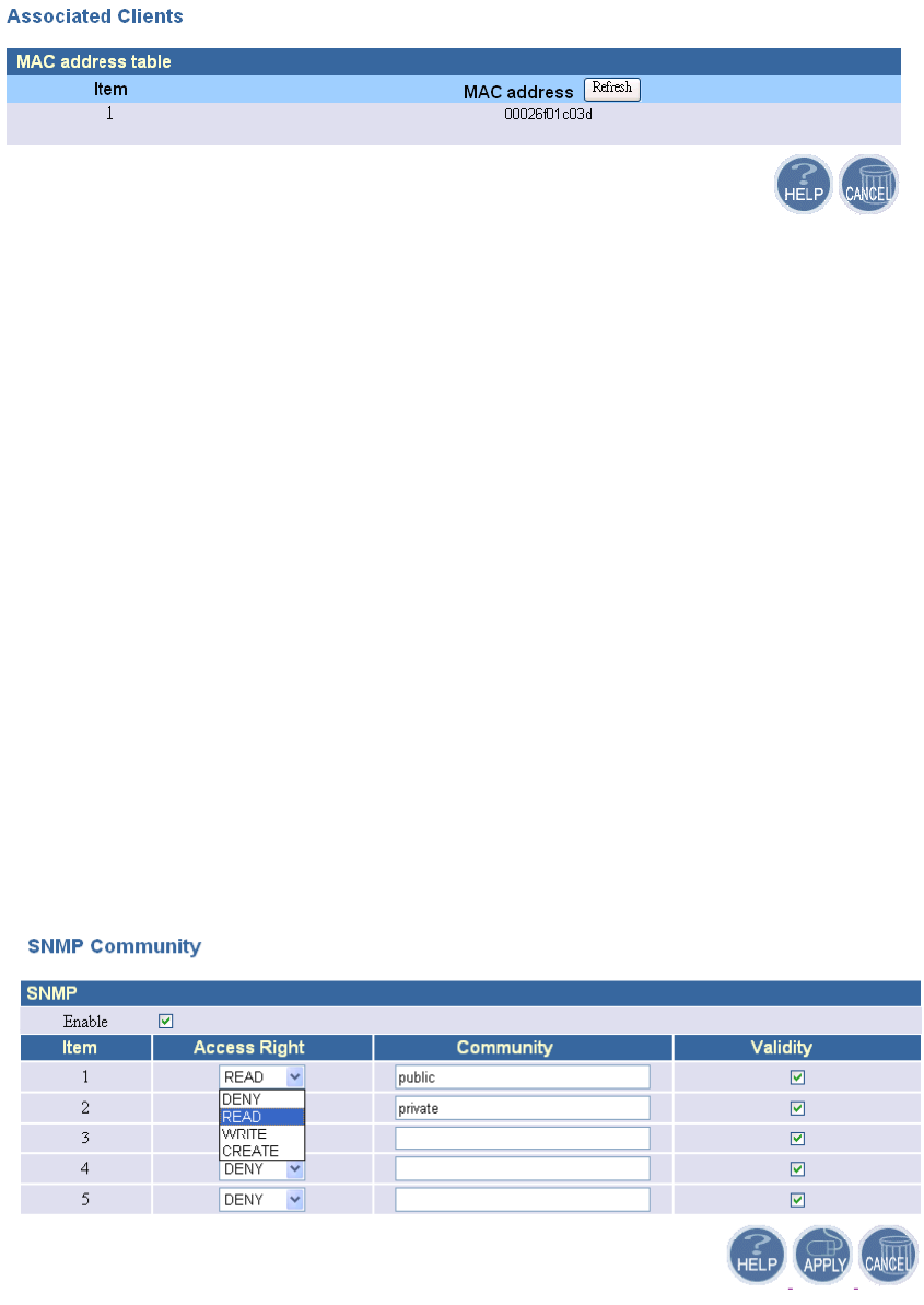
4.4.3 Associated Clients
This page lists all the associated clients. Click Refresh to obtain the most up-to-date
information.
4.5 SNMP
Short for Simple Network Management Protocol, a set of protocols for managing complex
networks. SNMP works by sending messages, called protocol data units (PDUs), to different parts
of a network. SNMP-compliant devices, called agents, store data about themselves in Management
Information Bases (MIBs) and return this data to the SNMP requesters.
4.5.1 SNMP Community
SNMP Community provides a simple kind of password protection. Access to the SNMP
device is controlled through community names. The community name can be thought of as a
password. If you don't have the correct community name you can't retrieve any data (get) or make
any changes (sets). Multiple SNMP managers may be organized in a specified community. You can
change your SNMP community settings on this screen. Check the “Enable” check box to enable the
SNMP function. Click APPLY to complete your change.
21
Validity: You can enable or disable the SNMP function of the corresponding community item.
Access Right: Select a access right for the corresponding SNMP community
(Deny4/Read5/Write6).
Community: Specify the name of community for the SNMP manager( Private/Public). By
convention, “Public” community is with a read-only access right.
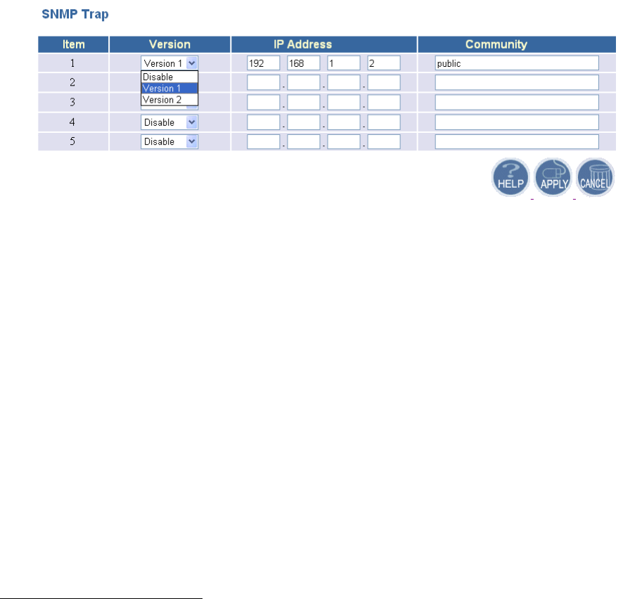
4.5.2 SNMP Trap
Traps can be used by network entities to signal abnormal conditions to management stations.
SNMP TRAP message can be sent to a host. Click APPLY to complete your settings.
Version: Select the SNMP Version.
Select “Disable” to disable the snmp trap function of the corresponding item.
Version1: SNMP Version1
Version2: SNMP Version2
IP Address: Specify the IP Address of the SNMP Manager for SNMP Trap Report.
Community: Specify the type of community ( public/Private) for SNMP manager.
Following are the traps supported in the access point:
Cold-start trap:
This trap indicates that the specified node's power has just come on. The cold-start trap is
generated every time the access point is power-cycled. Cold-start traps are not generated
until three seconds after the access point is power-cycled. This allows time for the hardware
4 Deny community will not allow a remote device to read information from a device or to modify settings on that
device.
5 Read-only community enables a remote device to retrieve "read-only" information from a device.
6 Read-Write community allows a remote device to read information from a device and to modify settings on that
device.
22
providing the low-level IP network interface to start up and stabilize before attempting to
send a packet.
5 Configuring the Access Point through Telnet
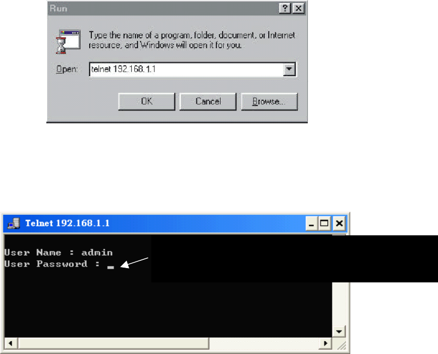
5.1 Enter the Telnet session
1. Click Start button, select Run to open the Run dialog box as shown below. Enter telnet
192.168.1.1 (default IP address of AP is 192.168.1.1) in the Open field. Then click OK
button.
2. After entering the telnet session, enter the User Name and User Password as shown below.
(Default User Name is admin and there is no default User Password).
No default password. Just press “Enter”

23
3. After entering the telnet daemon, you can first type help to see the available commands.
Command Line Interface v 1.0
==================================================
====
time : Get current system time.
Usage: time
settime : Set system time.
Usage: settime <hh:mm:ss> [yy/mm/dd] [TZ(GMT +/- hour)]
help : List all commands.
Usage: help
ifShow : Dispaly network interface.
Usage: ifShow <ifname>
ipConfig : Configure interface address and subnet mask.
Usage: ipConfig [ifname] [ip] [subnet mask]
ping : Ping a host..
Usage: ping [ip]
routeShow : Show Route.
Usage: routeShow
dhcpsStart: Start DHCP Server..
Usage: dhcpsStart
dhcpsStop : Stop DHCP Server..
Usage: dhcpsStop
exit : exit this telnet session.
Usage: Exit
wlanShow : Show the WLAN config.
Usage: wlanShow
reset : reset the system.
Usage: reset
wlanSet : configure the wireless part.
Usage: wlanset ACTION [arg1], [agr2], ...
status : Show the AP status.
Usage: status
sysSet : Change the System Configuration.
Usage: sysSet ACTION [arg1], [agr2], ...
lanShow : Show the LAN setting.

24
5.2 Command Line for Telnet daemon
1. “time” command shows current system time. Just type “time” at command line prompt.
2. Use “settime” to change the current system time.
Usage: settime <hh:mm:ss> [yy/mm/dd] [TZ(GMT +/- hour)]
cmd>time
Time zone: GMT+6
Local time: Thu Jan 1 00:59:10 1970
GMT time: Thu Jan 1 06:59:10 1970
cmd>

25
3. “ifShow” command shows all network interface information, including IP address, subnet
mask, and information of packets.
Usage: ifShow [ifname]
To show all network interface, just type “ifShow” at command line prompt.
lo - Loopback interface.
adm – LAN interface.
wlan – Wireless LAN interface.
cmd>settime 15:50:00 2002/12/13
cmd>time
Time zone: GMT+6
Local time: Fri Dec 13 15:50:02 2002
GMT time: Fri Dec 13 21:50:02 2002
cmd>
cmd>ifShow
lo (unit number 0):
Type: SOFTWARE_LOOPBACK
Internet address: 127.0.0.1
Netmask 0xff000000 Subnetmask 0xff000000
Metric is 0
Maximum Transfer Unit size is 1536
0 packets received; 0 packets sent
0 multicast packets received
0 multicast packets sent
0 input errors; 0 output errors
0 collisions; 0 dropped

26
4. “ipConfig” command is used to configure interface address and subnet mask.
Usage: ipConfig [ifname] [ip] [subnetMask]
adm (unit number 0):
Type: ETHERNET_CSMACD
Internet address: 192.168.1.1
Broadcast address: 192.168.1.255
Netmask 0xffffff00 Subnetmask 0xffffff00
Ethernet address is 00:01:02:03:04:05
Metric is 0
Maximum Transfer Unit size is 1500
1016 packets received; 686 packets sent
189 multicast packets received
21 multicast packets sent
0 input errors; 0 output errors
0 collisions; 0 dropped
wlan (unit number 0):
Type: ETHERNET_CSMACD
Netmask 0x1114 Subnetmask 0x111c
Ethernet address is 00:02:6f:01:c0:3f
Metric is 0
Maximum Transfer Unit size is 1500
0 packets received; 209 packets sent
0 multicast packets received
0 multicast packets sent
0 input errors; 0 output errors
0 collisions; 0 dropped
cmd>

27
I
ask]
5. “ping” command is used to ping a host.
Usage: ping [IP address]
6. “exit” command exit the telnet session. Type “exit” at command line prompt.
7. “wlanShow” command shows the wireless LAN configuration, including SSID, Channel,
WEP Encryption information, threshold information, and security information. Just type
“wlanShow” at command line prompt.
Welcome to Telnet Daemon v1.00
cmd>ipConfig adm0 192.168.1.50 255.255.255.0
cmd>
Interface name IP address
of interface Subnet Mask
cmd>ping 192.168.1.20
Start time 14671
Reply from 192.168.1.20
End time 14673
Ping statics for 192.168.1.20:
Packets: Sent = 1, Received = 1, Lost = 0
cmd>exit
Exit this telnet session
cmd>wlanShow
------- AP configuration ---------
MAC address 00:02:6f:01:c0:3d
SSID: Candice
Channel: 6
WEP: Disable
Authentication algorithm: Open System

28
8.“reset” command can reboot the system. Just type ”reset” at command line prompt.
9. “status” shows current information and settings for your AP.
Default Wep key Id(1-4): 1
WEP key len: 64-bit
Key 1: 00000000000000000000000000
Key 2: 00000000000000000000000000
Key 3: 00000000000000000000000000
Key 4: 00000000000000000000000000
--- Wireless Enhanced Features ---
Power Level: MAX(original)
Fragment Threshold: 2346
RTS Threshold: 2432
Beacon Interval 100 (max: 4095 ms default :100ms)
Max associated stations: 250
Wireless Client Isolation: Disable
Hide SSID: Disable
Block Responds to 'Unspecified-SSID': Disable
AP Link Completeness: Disable
cmd>status
--------- LAN -----------------
IP: 192.168.1.98
Subnet Mask: 255.255.255.0
Gateway: 0.20.247.208
LAN MAC Address: 00:01:02:03:04:10
Connected DHCP Clients: 1
--------- Wireless -----------------
SSID: [(null)]
Channel: 6
Authentication type: None
Wireless MAC Address: 00:02:6f:01:c0:3dWireless MAC Address:

29
10. “routeShow” shows the network routing table, host routing table and the ARP table.
cmd>routeShow
Net Routing Table:
Destination Gateway NetMask Flags Used Hops Interface
----------------------------------------------------------------------------------------------------------
192.168.3.0 192.168.3.1 255.255.255.0 U C 0 0 adm0
Host Routing Table:
Destination Gateway NetMask Flags Used Hops Interface
-------------------------------------------------------------------------------------------------------
127.0.0.1 127.0.0.1 U H 0 0 lo0
ARP Table:
Destination Gateway NetMask Flags Used Hops Interface
------------------------------------------------------------------------------------------------------
192.168.3.20 00:00:e2:7a:59:3f U H L 3377 0 adm0
192.168.3.25 00:02:6f:01:c0:3d U H L 3142 0 adm0
cmd>
11.“dhcpsStart” command enables the DHCP server function. The AP can function as a DHCP
server and automatically assign an IP address to a client.
cmd>dhcpsStart
DhcpsStart: successful!
12. “dhcpsStop” command can stop the DHCP server function.
--------- System Information -----------------
System Up time: 01:26:55
Local time: Thu Jan 1 01:26:55 1970
GMT time: Wed Dec 31 17:26:55 1969
Current Firmware Version: [1.00.4455]
Firmware Date: [2003.01.06]
Hardware Version: [1]
Serial Number: [0000011118]
cmd>

30
Welcome to Telnet Daemon v1.01
cmd>dhcpsStop
cmd>
13. “lanShow” command shows the LAN configuration and DHCP configuration, including IP
address, Subnet Mask, DHCP status, and IP pool information.
cmd>lanShow
---==== LAN configuration ====---
IP Address: 192.168.1.98
Subnet Mask: 255.255.255.0
Gateway: 0.0.0.0
DHCP Server: Enabled
IP Pool Starting Address: 192.168.1.2
IP Pool Ending Address: 192.168.1.254
Lease Time: One hour
Local Domain Name:
---==== DHCP configuration ====---
Item IP MAC Address Host name
1 192.168.1.2 00:02:6f:01:c0:3e wlan-w2k
cmd>
14.“filterShow” displays the MAC address filtering table, filtering type, and the information of IP
filtering.
Welcome to Telnet Daemon v1.01
cmd>filterShow
---====== MAC control list ---======
Filtering type: Disabled (Any station can access)
Item MAC Select
---------------------------------------------
1 00:02:6f:01:c0:3f Selected
2 00:00:00:00:00:00 Unselect
3 00:00:00:00:00:00 Unselect
4 00:00:00:00:00:00 Unselect
…..
…..
…..
---==== IP Filter Configuration ====---
--------------------------------------
IP Port Type Block Day Time
192.168.3.0- 0 0- 0 TCP Always N/A- N/A N/A- N/A Disable
192.168.3.0- 0 0- 0 TCP Always N/A- N/A N/A- N/A Disable
192.168.3.0- 0 0- 0 TCP Always N/A- N/A N/A- N/A Disable
192.168.3.0- 0 0- 0 TCP Always N/A- N/A N/A- N/A Disable

31
192.168.3.0- 0 0- 0 TCP Always N/A- N/A N/A- N/A Disable
192.168.3.0- 0 0- 0 TCP Always N/A- N/A N/A- N/A Disable
192.168.3.0- 0 0- 0 TCP Always N/A- N/A N/A- N/A Disable
192.168.3.0- 0 0- 0 TCP Always N/A- N/A N/A- N/A Disable
cmd>
15. “snmpShow” shows SNMP configuration. It displays the information of SNMP Community
and SNMP Trap. Type “snmpShow” at the command line prompt.
cmd>snmpShow
---==== SNMP Information ====---
SNMP Status: Enable
---==== SNMP Community info ====---
--------------------------------------------------------------------------
Item Access Right Community Validity
1 WRITE public Enable
2 CREATE private Enable
3 DENY Enable
4 DENY Enable
5 DENY Enable
Version of
SNMP
IP address for SNMP
Trap report
---==== SNMP Trap info ====---
Item Version IP Community
------------------------------------------------------
1 version 1 192.168.1.2 public
2 disable
3 disable
4 disable
5 disable

32
5.3 Configuring Wireless LAN through Telnet
The command “wlanSet” can configure the Wireless LAN part. Type “wlanSet” and the action
you want to perform. You need to know actions for the Wireless LAN setting.
Usage: wlanSet [ACTION] [arg1] [arg2] ….
ACTION Description Usage
ssid Change the SSID wlanSet ssid [SSID]
channel Change the wireless
channel[1-14]
wlanSet channel [channel
number]
frag Change the fragment
Threshold
wlanSet frag [fragment
threshold]
rts Change the RTS Threshold wlanSet rts [RTSThreshold]
keyid Change the WEP default
key id [1-4]
wlanSet keyid [defualt key
id]
beacon Change the beacon Period
[0-4095ms]
wlanSet beacon [beacon
period]
maxass Change the max associated
stations [1-300]
wlanSet maxass [number of
stations]
wepkey Change the WEP key wlanSet wepkey [keyid]
[key(hex format)]
wep wlanSet wep [0|64|128] wlanSet wep [0|64|128]
isolate Change the Wireless Client
Isolation: 0:disable,
1:enable
wlanSet isloate [0|1]
hidessid Change the Hide SSID:
0:disable, 1:enable
wlanSet hidessid [0|1]
block Change the Block Responds
to 'Unspecified-SSID':
0:disable, 1:enable
wlanSet block [0|1]
power Change the Outpower level:
0:Original, 1: 100mW, 2:
50mW, 3: 20mW
wlanSet power [0|1|2|3]
aplink Change the AP Link
Completeness: 0:disable,
1:enable
wlanSet aplink [0|1]
authalgo Change Authentication wlanSet authalgo [1|2|3]

33
ACTION Description Usage
algorithm: 1:Open system,
2: Shared key, 3:Auto
1. The “ssid” action can change the SSID
Usage: wlanSet ssid [New SSID]
2. The “channel” action can change the wireless channel.
Usage: wlanSet channel [New channel number]
3. The “frag” action can change the frame’s fragment threshold.
Fragment Threshold: 256~2346 bytes , default is 2346
Usage: wlanSet frag [ New fragment threshold]
4. The “rts” action can change the frame’s RTS threshold.
RTS Threshold: 0~3000 ms, default is 2432
Usage: wlanSet rts [Nes RTS threshold]
cmd>wlanSet ssid WirelessLAN
Old SSID: Wireless
New SSID (after reset): WirelessLAN
(Please remember to reset the Access Point if you made any change).
cmd>wlanSet channel 5
Old Channel: 6
New Channel (after reset): 5
(Please remember to reset the Access Point if you made any change).
cmd>wlanSet frag 2000
Old Fragment Threshold: 2346
New Fragment Threshold (after reset): 2000
(Please remember to reset the Access Point if you made any change).
New SSID
cmd>wlanSet rts 2500
Old RTS Threshold: 2432
New RTS Threshold (after reset): 2500
(Please remember to reset the Access Point if you made any change).

34
5. The “keyid” action can change the WEP default ID( the default is from 1 to 4).
Usage: wlanSet keyid [New key default ID]
6. The “beacon” action can change the beacon period.
Beacon Period: Default is 100 ms. The maximum is 4095.
Usage: wlanSet beacon [New beacon period]
7. The “maxass” action can set the maximun number of users that can associate the AP.
8. The “wepkey” action can change the WEP key.
Usage: wlanSet wepkey [keyid] [key(hex format)]
9. The action “wep” is for changing the WEP key length (0:disable/64 bit/128 bit).
Usage: wlanSet wep [New key length]
cmd>wlanSet keyid 2
Old WEP default key id: 0
New WEP default key id (after reset): 2
(Please remember to reset the Access Point if you made any change).
cmd>wlanSet beacon 3000
Old Beacon Period: 100
New Beacon Period (after reset): 3000
(Please remember to reset the Access Point if you made any change).
cmd>wlanSet maxass 20
Old Maximum Assocated Stations: 250
New Maximum Assocated Stations (after reset): 20
(Please remember to reset the Access Point if you made any change).
cmd>wlanSet wepkey 1 1122334455
CmdWlanSetKey() key 1122334455
Old Key 1: 0011223344
New Key 1: 1122334455
(Please remember to reset the Access Point if you made any change).

35
Example:
To disable the WEP key, type following command:
10. The “isolate” action can enable/disable the wireless client isolation function.
0: Disable
1: Enable
Usage: wlanSet isolate [0|1]
11. The “hidessid” action can enable/disable the “Hide SSID in beacon frame” function.
0: Disable
1: Enable
Usage: wlanSet hidessid [0|1]
cmd>wlanSet wep 128
Old WEP Encryption: 64-bit
New WEP Encryption (after reset): 128-bit
(Please remember to reset the Access Point if you made any change).
cmd>wlanSet isolate 1
Old Wireless Client Isolation: Disable
New Wireless Client Isolation (after reset): Enable
(Please remember to reset the Access Point if you made any change).
cmd>wlanSet hidessid 1
Old Hide SSID: Disable
New Hide SSID (after reset): Enable
(Please remember to reset the Access Point if you made any change).
cmd>wlanSet wep 0
Old WEP Encryption: 64-bit
New WEP Encryption (after reset): Disabled
(Please remember to reset the Access Point if you made any change).

36
12. The “block” action can enable/disable the ”Block responds to Unspecified-SSID” function.
0: Disable
1: Enable
Usage: wlanSet block [0|1]
13. The “power” action can change the power level 0:Original, 1: 100mW, 2: 50mW, 3: 20mW
0:Original
1: 100mW
2: 50mW
3: 20mW
Usage: wlanSet power [0|1|2|3]
If plug off the cable of LAN interface,
14. The “aplink” action can change the AP Link Completeness. If enable this function, the WLAN
interface will be disabled when plug off the cable of LAN interface,
0: Disable
1: Enable
Usage: wlanSet aplink [0|1]
cmd>wlanSet block 0
Old Block Responds to 'Unspecified-SSID': Enable
New Block Responds to 'Unspecified-SSID' (after reset): Disable
(Please remember to reset the Access Point if you made any change).
cmd>wlanSet power 2
Old Power Level: MAX(original)
New Power Level (after reset): 50mW
(Please remember to reset the Access Point if you made any change).
cmd>wlanSet aplink 1
Old AP Link Completeness: Disable
New AP Link Completeness (after reset): Enable
(Please remember to reset the Access Point if you made any change).

37
15. The “authalgo” action can change the authentication algorithm.
1: Shared key
2: Open system
3: Auto
Usage: wlanSet authalgo [1|2|3]
5.4 Configuring LAN through Telnet
The command “lanSet” can configure the LAN part. Type “lanSet” and the action you want to
perform. You need to know actions for the LAN setting.
Usage: lanSet [ACTION] [arg1] [arg2] ….
ACTION Description Usage
ip Change the LAN’s IP and
mask
LanSet ip [IP] [mask]
gateway Change the AP IP, mask,
Gateway, DHCP
lanSet gateway [gateway]
dhcp Change the DHCP server
setting.
lanSet dhcp ['disable'|start
ip] [end ip] [lease time]
[domain name]
1. The “ip” action can change the LAN’s IP address and Subnet Mask.
Usage: lanSet ip [IP] [mask]
Example:
Welcome to Telnet Daemon v1.01
cmd>wlanSet authalgo
Current Authentication algorithm: Open System
cmd>wlanSet authalgo 3
Old Authentication algorithm: Open System
New Authentication algorithm (after reset): Auto
(Please remember to reset the Access Point if you made any change).
cmd>

38
2. The “gateway” action can set the network’s gateway.
Usage: lanSet gateway [gateway IP]
Example:
3. The “dhcp” action can change the dhcp server setting.
Usage: lanSet dhcp ['disable' | start ip] [end ip] [lease time] [domain name]
Argument Description Usage
'disable'|start ip disable: to disable the DHCP server function
start ip: the start IP address of the IP pool
end ip The ending IP address of the IP pool
lease time: The period client can have the IP
address assigned by DHCP server.
0: Half hour, 1: One hour, 2: Two hours, 3:Half
day, 4: One day, 5: Two days, 6: One week,
7:Two weeks 8: Forever
domain name: the domain name (needed by
some applications)
Usage: To disable the dhcp server, type: lanSet dhcp 'disable'
To enable the dhcp server, type:
lanSet dhcp ['disable' | start ip] [end ip] [lease time] [domain name]
Example:
cmd>lanSet gateway 192.168.3.47
Change gateway success.
(Please remember to reset the Access Point if you made any change).
cmd>
cmd>lanSet ip 192.168.3.1 255.255.255.0
argc 3, ip [192.168.3.1] mask [255.255.255.0]
(Please remember to reset the Access Point if you made any change).
cmd>lanSet dhcp disable
disable the DHCP server
(Please remember to reset the Access Point if you made any change).
cmd>

39
5.5 Configuring System through Telnet
The command “sysSet” can change the settings of system, including time and administrator
settings. Type “sysSet” and the action you want to perform. You need to know actions for filter
setting.
Usage: sysSet [ACTION] [arg1][arg2]…..
ACTION Description Usage
passwd Change the password. sysSet passwd
idletime Change the IdleTimeOut. sysSet idletime [idle time
(mins)]
remote Change the Remote
Management status
sysSet remote [0|1][IP]
fwupgrade firmware upgrade. sysSet fwupgrade [IP] [file]
setdefault Set to default system
configuration.
sysSet setdefault
reset reset the system. sysSet reset
sntppoll Change the SNTP polling
time
sysSet sntppoll
sntp Change the SNTP setting sysSet sntp [0|1] [IP]
sntpchangeip Change a SNTP server's IP. sysSet sntpchangeip
[INDEX] [IP], index: 1-4
1. The “passwd” action can change the system password.
Usage: sysSet passwd
Example:
cmd>lanSet dhcp 55 66 1 domainname
LAN set DHCP ok!
(Please remember to reset the Access Point if you made any change).
cmd>
Welcome to Telnet Daemon v1.01
cmd>sysSet passwd
**** Change password ****
Please enter current password:
Please enter new password: ****
Please re
-
enter new password:
****

40
2. The “idletime” action can change the system idle time out.
Usage: sysSet idletime [idle time(min)]
3. The “remote” action can enable or disable the remote management function. You can enter
the IP address of the remote manager.
Usage: sysSet remote [0|1] [IP of remote manager]
0: disable
1: enable
Example:
4. The ”fwupgrade” action can do the firmware upgrade.
Usage: sysSet fwupgrade [IP] [file]
Example:
cmd>sysSet idletime 98
New Idle time value out is 98 min(s)
(Please remember to reset the Access Point if you made any change).
cmd>
cmd>sysSet remote
Current Remote Management status: Disabled
cmd>sysSet remote 1 192.168.3.25
New Remote Management status: Enabled
(Please remember to reset the Access Point if you made any change).
cmd>
Welcome to Telnet Daemon v1.01
cmd>sysSet fwupgrade 192.168.3.20 application.dlf
Current Firmware Version: 1.00.4431
Firmware Date: 2003.01.02
TFTP download start
TFTP download successed
(Please remember to reset the Access Point if you made any change).

41
5. The “setdefault” action can reset system to factory default configuration. This command is
the same as the “Restore Factory Default Configuration” function of the Web-Based utility.
Usage: sysSet setdefault
Example:
Note: You have to reset system to let this change effective.
6. The “reset” action can reboot the system and refresh the AP’s connection.
Usage: sysSet reset
7. The “sntppoll” action can change the SNTP pooling time.
Usage: sysSet sntppoll [polling time(sec)]
Example:
Welcome to Telnet Daemon v1.01
cmd>sysSet setdefault
Load default system configuration
Load default system configuration finished
cmd>sysSet sntppoll
Current SNTP polling time value is 86400 second(s)
cmd>
Welcome to Telnet Daemon v1.01
cmd>sysSet sntppoll 11000
New SNTP polling time value is 11000 second(s)
(Please remember to reset the Access Point if you made any change).
cmd>

42
8. The “sntp” action can change SNTP function and set SNTP server.
Usage: sntp [0|1] [IP]
0: Disable
1: Enable
Example:
9. The “sntpchangeip” action can change SNTP server’s IP.
Usage: sntpchangeip [Index] [sntp server’s IP]
index: 0-4
Example:
cmd>sysSet sntp 0
New SNTP status: Disabled
(Please remember to reset the Access Point if you made any change).
cmd>sysSet sntp 1 192.168.3.20
New SNTP configuration
Usage: sntp [0|1] [IP], 0:disable, 1:enable
---==== SNTP configuration ===---
Status: Enable
Polling time: 86400 seconds
Server #1's IP: 192.168.3.20
Server #2's IP: 0.0.0.0
Server #3's IP: 0.0.0.0
Server #4's IP: 0.0.0.0
(Please remember to reset the Access Point if you made any change).
cmd>sysSet sntpchangeip 1 192.168.3.25
New setting:
---==== SNTP configuration ===---
Status: Enable
Polling time: 86400 seconds
Server #1's IP: 192.168.3.25
Server #2's IP: 0.0.0.0
Server #3
'
sIP:0000

43
5.6 Configuring Filtering through Telnet
The command “filterSet” can change the settings of MAC filtering and IP filtering. Type
“filterSet” and the action you want to perform. You need to know actions for filter setting.
Usage: filterSet [ACTION] [arg1][arg2]…..
ACTION Description Usage
macshow Show the MAC filtering
setting.
filterSet macshow
mac Change the MAC address
filtering.
filterSet mac ….
ip Show the IP filtering
setting.
filterSet ip ….
ipdaytime Change the daytime part filterSet ipdaytime
ipstatus Enable or Disable the IP
filtering function.
filterSet ipstatus
1. The “macshow” action shows the filtering type and MAC address table of MAC filtering.
Usage: filterSet macshow
cmd>filterSet macshow
---====== MAC control list ---======
Filtering type: Disabled (Any station can access)
Item MAC Select
---------------------------------------------
1 00:02:6f:01:c0:3f Unselect
2 00:00:00:00:00:00 Unselect
3 00:00:00:00:00:00 Unselect
4 00:00:00:00:00:00 Unselect
………….
………….
………….

44
2. “mac” action can change the settings of MAC address filtering. You can change filtering
type. You can select ,unselect or clear those MAC address item.
Description Usage
Set filtering type to 'disable' filterSet mac disable
Set filtering type to 'include' filterSet mac include
Set filtering type to 'exclude' filterSet mac exclude
Set mac address filterSet mac setmac [index] [MAC address]
index: 1...1291632,
MAC address format : 00-00-01-02-03-04-05
Select a mac address filterSet mac select [index]
index: 1...64
Unselect a mac address filterSet mac unselect [index]
index: 1...64
Clear a mac address filterSet mac clear [index]
index: 1...64
Clear all mac addresses filterSet mac clearall
3. The “ip” action can set the IP and port to be block. You can set the protocol type to be block.
Usage: filterSet ip [Index] [Start IP] [End IP] [Start port] [End port] [Protocol]
Argument Description
index: the (index)th item to be modified index : 1 .. 8
Start IP the last byte of the Start IP
End IP the last byte of the End IP
Start port the first port being blocked
End port the last port being blocked
Protocol: the protocol type Type “tcp” or “udp”
Example:
cmd>filterSet ip 2 45 78 21 21 udp
Set to index 2 Source IP Start: 45 Source IP end: 78 PortStart 21 PortEnd 21 pro
tocol 2
Ok

45
4. The “ipdaytime” can set the day and time to block the IP address.
Usage: filterSet ipdaytime index [Start day] [End day] [Start hour] [End hour]
Example: filterSet ipdaytime 1 MON FRI 9am 6pm
Argument Description Usage
index: the (index)th item to be modified index : 1 .. 8
Start day: the day start to block SUN, MON, TUE, WED, THU, FRI, SAT
End day: the day stop to block SUN, MON, TUE, WED, THU, FRI, SAT
Start hour: the time start to block 0am, 1am, 2am, 3am, 4am, 5am, 6am, 7am,
8am, 9am, 10am,11am, 12am, 1pm, 2pm, 3pm,
4pm, 5pm, 6pm, 7pm, 8pm, 9pm,10pm, 11pm
End hour: the time stop to block 0am, 1am, 2am, 3am, 4am, 5am, 6am, 7am,
8am, 9am, 10am 11am, 12am, 1pm, 2pm, 3pm,
4pm, 5pm, 6pm, 7pm, 8pm, 9pm,10pm, 11pm
5. The “ipstatus” action can enable and disable the IP filtering function.
Usage: filterSet ipstatus [index] [status]
Example: filterSet ipstatus 1 2
Argument Description Usage
index: the (index)th item to be modified index : 1 .. 8
status 0: disable, 1:enable, 2:always block, 3:block
on time
Note: If you choose 3 (block on time) for status, you have to indicate the day and time by
using the “ipdaytime” action.
5.7 Configuring SNMP through Telnet
The command “snmpSet” can change the settings of SNMP. Type “snmpSet” and the action you
want to perform. You need to know actions for snmp setting.
Usage: snmpSet [ACTION] [arg1] [arg2]…..

46
1. The “comstatus” action can enable or disable the community status.
Usage: snmpSet comstatus [0|1]
0: Disable
1: Enable
2. The “community” action can change the settings of SNMP community.
Usage: snmpSet community [item] [Access Right] [Community] [Validity]
Argument Description Usage
item item: 1 .. 5
Access Right: Select a access right for the
corresponding SNMP community
Type “deny”, “read”, “write”, “create” for
different access right
Validity: enable or disable the SNMP function
of the corresponding community item.
0:disable, 1:enable
Example:
3. The “trap” action can change the settings of SNMP trap.
Usage: snmpSet trap [item] [version] [ip] [community]
Argument Description Usage
item item: 1 .. 5
Version: the version of SNMP 0:disable, 1: Version 1, 2: Version 2
ACTION Description Usage
comstatus Enable or disable the
SNMP community function
snmpSet comstatus [0|1]
community Change the SNMP
community setting.
snmpSet community
[index] [access right]
[community] [validatiy]
trap Change the SNMP trap
setting.
snmpSet trap [index]
[version] [IP] [community]
Welcome to Telnet Daemon v1.01
cmd>snmpSet community 1 read public 1
SNMP community set ok.
(Please remember to reset the Access Point if you made any change).

47
Example:
cmd>snmpSet trap 3 2 192.168.1.1 public
SNMP trap set ok.
(Please remember to reset the Access Point if you made any change).

48
5.8 Upgrading Firmware through Telnet
If problem happens during firmware upgrading (e.g.. Power off abnormally), the AP may not
work normally. If this is the case, the AP will start a Telnet Daemon on the LAN interface. After
that, user can telnet to the AP and make a firmware upgrade using TFTP method. By doing so,
user can make AP works again.
1. You will see the warning message shown as below:
2. Connect the managed computer and the AP’s LAN port with an Ethernet cable.
3. Telnet to the AP. Make sure the AP’s IP Address is the one when problem happened.
4. Type the fixed User Name and Password ( User Name: root / Password: tftp ) to enter the telnet
session.
Verifying product code......FAIL
***** WARNING *****
Need to reprogram the Flash. Telnet init
Enter into daemon : Telnet listen Port 23
***** WARNING *****
Need to reprogram the Flash!
User Name :
***** WARNING *****
Need to reprogram the Flash!
User Name : root
User Password : tftp

49
5. Type help to list all command.
6. On the managed computer, run the TFTP Server utility. Make sure to specify the folder in
which the firmware files reside.
7. To perform the firmware upgrade, use tftp command.
Usage: tftp [IP Address] [ File Name]
cmd>help
Command Line Interface v 1.0
==============================================
time : Get current system time.
Usage: time
help : List all commands.
Usage: help
tftp : tftp download.
Usage: tftp [IP] [file]
ipConfig : Configure interface address and subnet mask.
Usage: ipConfig [ifname] [ip] [subnet mask]
ifShow : Dispaly network interface.
Usage: ifShow <ifname>
reset : reset the system.
Usage: reset
ping : Ping a host..
Usage: ping [ip] [ms]
Welcome to Telnet Daemon v1.00
cmd>tftp 192.168.1.20 application.dlf
IP address of TFTP server Firmware file name

50
8. After downloading successfully, the AP will be reset and start running normally.
Telnet session will be closed after downloading successfully.
Welcome to Telnet Daemon v1.00
cmd>tftp 192.168.1.20 application.dlf
TFTP download start
TFTP download succeed
cmd>

51
6 Change History
Date Subject/Comment Old
Ve r s i o n
New
Ve r s i o n
12/16/02 N/A V1.0
12/16/02 WEP(auto), FW upgrade through telnet V1.0 V1.01
1/03/02 Telnet V1.01 V1.02
1/06/03 V1.02 V1.03
1/07/03 correction V1.03 V1.04
52
7 Statement
Federal Communication Commission Interference Statement
This equipment has been tested and found to comply with the limits for a Class B digital
device, pursuant to Part 15 of the FCC Rules. These limits are designed to provide
reasonable protection against harmful interference in a residential installation. This
equipment generates, uses and can radiate radio frequency energy and, if not installed and
used in accordance with the instructions, may cause harmful interference to radio
communications. However, there is no guarantee that interference will not occur in a
particular installation. If this equipment does cause harmful interference to radio or
television reception, which can be determined by turning the equipment off and on, the user
is encouraged to try to correct the interference by one of the following measures:
- Reorient or relocate the receiving antenna.
- Increase the separation between the equipment and receiver.
- Connect the equipment into an outlet on a circuit different from that
to which the receiver is connected.
- Consult the dealer or an experienced radio/TV technician for help.
FCC Caution: Any changes or modifications not expressly approved by the party
responsible for compliance could void the user's authority to operate this equipment.
This device complies with Part 15 of the FCC Rules. Operation is subject to the following
two conditions: (1) This device may not cause harmful interference, and (2) this device must
accept any interference received, including interference that may cause undesired operation.
IMPORTANT NOTE:
FCC Radiation Exposure Statement:
This equipment complies with FCC radiation exposure limits set forth for an uncontrolled
environment. This equipment should be installed and operated with minimum distance 20cm
between the radiator & your body.
This transmitter must not be co-located or operating in conjunction with any other antenna
or transmitter.