Senao Co 2511BG2PLUS Point-to-Point Wireless Outdoor Bridge User Manual 2511BG2 FCC
Senao International Co Ltd Point-to-Point Wireless Outdoor Bridge 2511BG2 FCC
UserManual.wiki
>
Senao Co
>
2511BG2PLUS User Manual
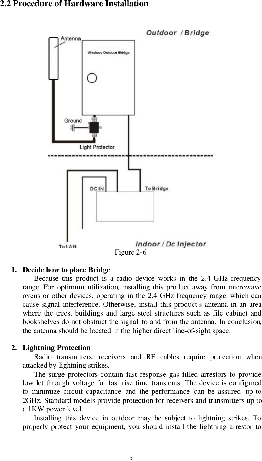
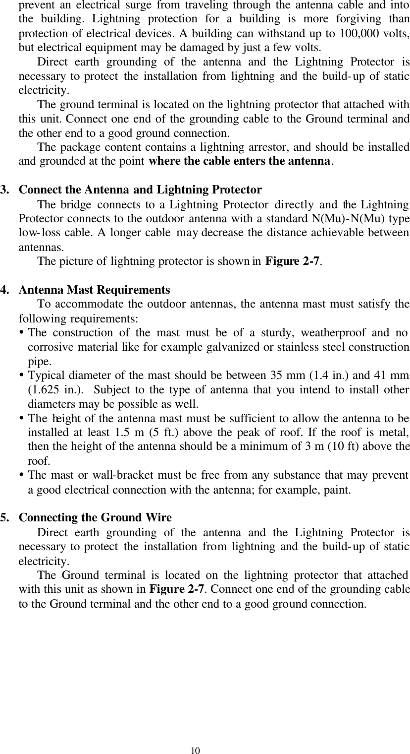
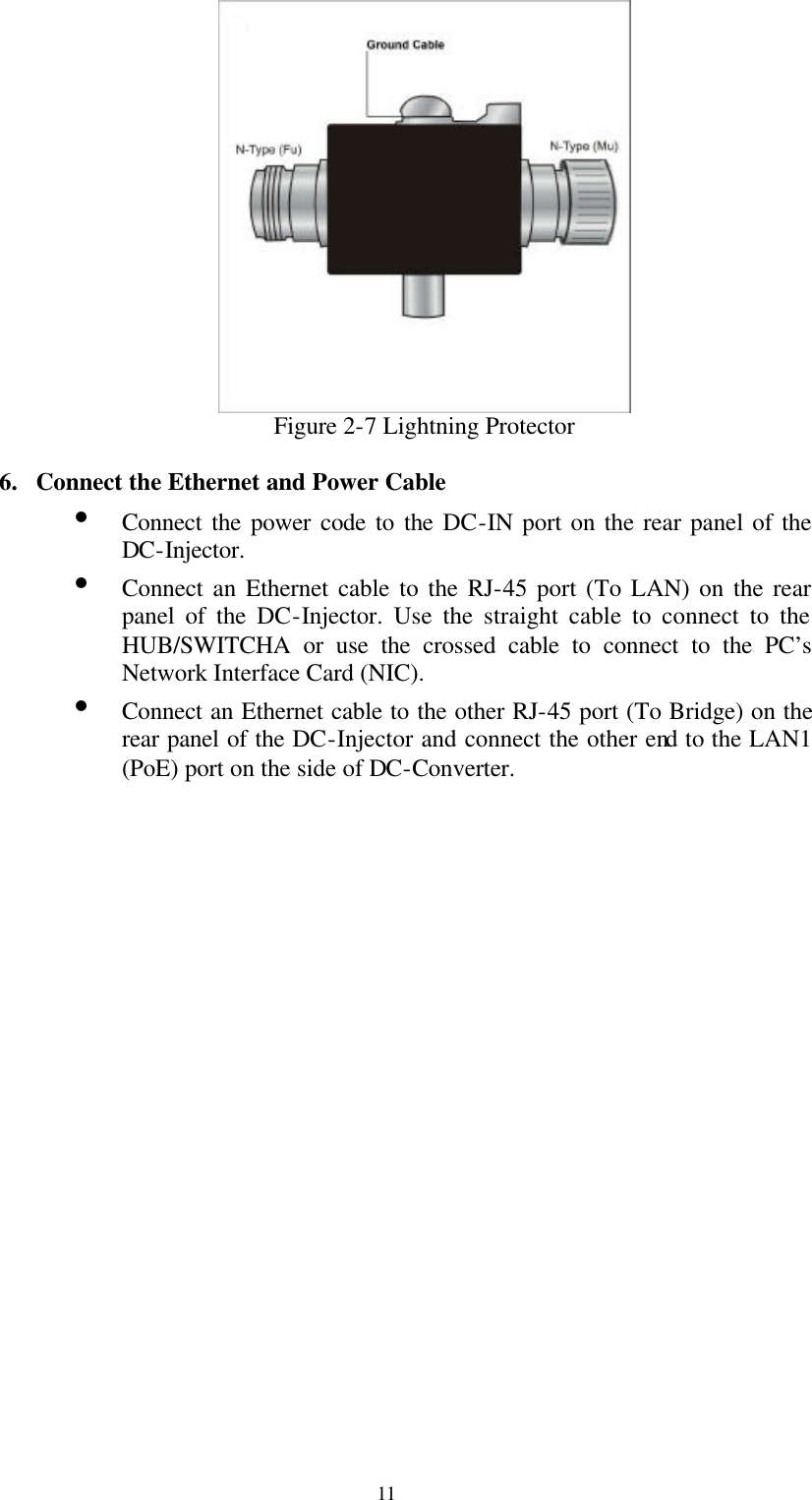
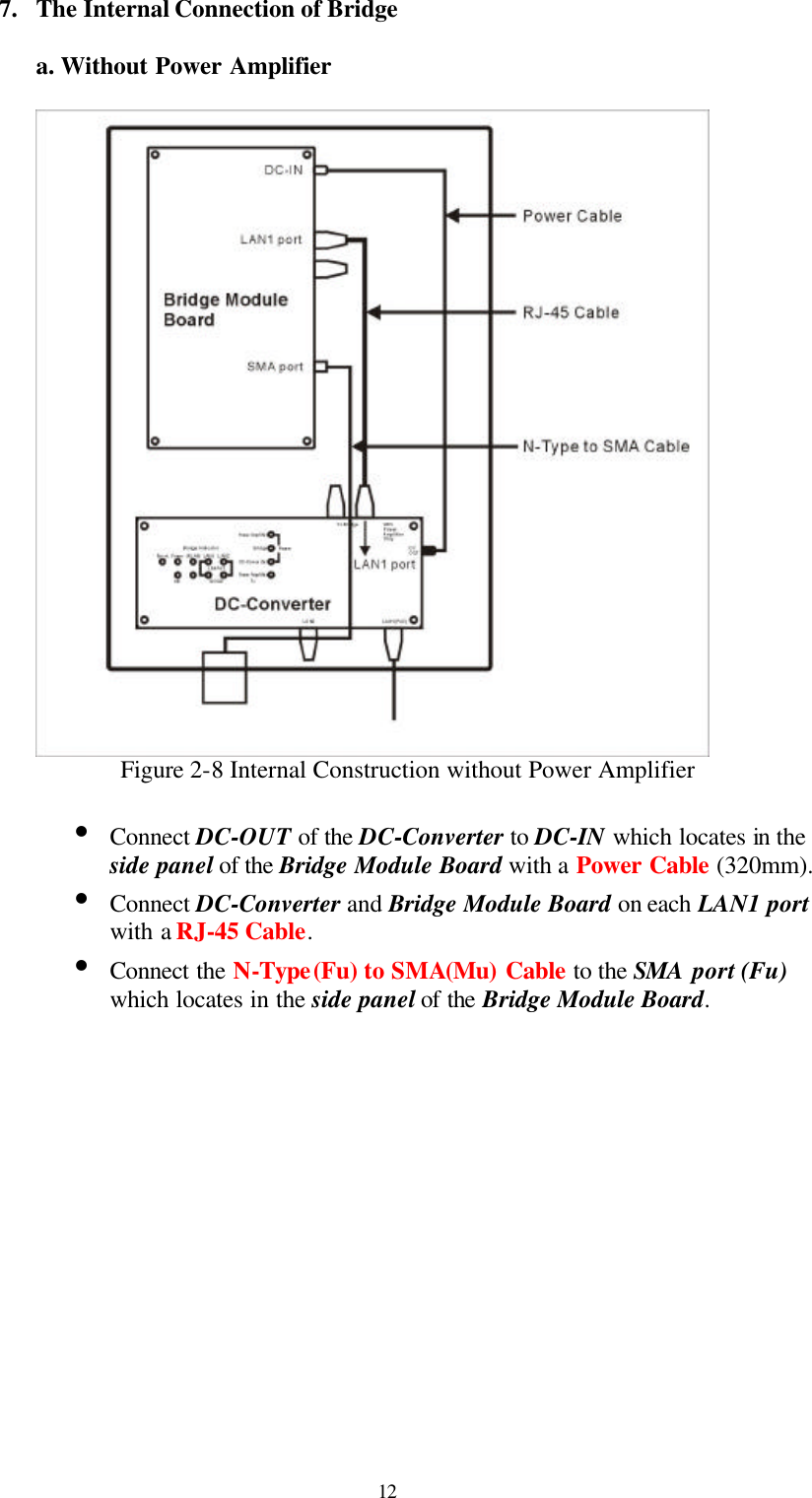
User Manual
Navigation menu
Upload a User Manual
Namespaces
Wiki Guide
HTML
PDF
Info
Views
User Manual
Discussion / Help
Navigation