Senao Co 2511BG2PLUS Point-to-Point Wireless Outdoor Bridge User Manual 2511BG2 FCC
Senao International Co Ltd Point-to-Point Wireless Outdoor Bridge 2511BG2 FCC
Senao Co >
User Manual

1
Wireless Outdoor Bridge
User Guide
Before operating the unit, please read this manual and retain it for future use
2
FCC Interference Statement
This equipment has been tested and found to comply with the limits for a Class B
digital device pursuant to Part 15 of the FCC Rules. These limits are designed to
provide reasonable protection against radio interference in a commercial environment.
This equipment can generate, use and radiate radio frequency energy and, if not
installed and used in accordance with the instructions in this manual, may cause
harmful interference to radio communications. Operation of this equipment in a
residential area is likely to cause interference, in which case the user, at his own
expense, will be required to take whatever measures are necessary to correct the
interference.
Notice : The changes or modifications not expressly approved by the party
responsible for compliance could void the user’s authority to operate the equipment.
IMPORTANT NOTE: To comply with the FCC RF exposure compliance
requirements, no change to the antenna or the device is permitted. Any change to the
antenna or the device could result in the device exceeding the RF exposure
requirements and void user’s authority to operate the device.
CE Declaration of Conformity
This equipment complies with the requirements relating to electromagnetic compatibility, ETS300/328,
ETS 301/489-17 and EN 60950. This meets the essential protection requirements of R&TTE Directive
99/5/EEC on the approximation of the laws of the member states relation to electromagnetic
compatibility.
IMPORTANCE NOTICE: To comply with FCC RF exposure compliance requirements, the
antenna used for this transmitter must be fixed-mounted on outdoor permanent structures
with a separation distance of at least 1.5 meter from all persons and must not be co-located
or operating conjunction with any other antenna or transmitter. No change to the antenna or
the device is permitted. Any change to the antenna or the device could result in the device
exceeding the RF exposure requirements and void user’s authority to operate the device.
3
Contents
Chapter 1 Introduction..................................................................................................4
1.1 Features and Benefits......................................................................................4
1.2 Packing List.....................................................................................................5
Chapter 2 Hardware Installation...................................................................................6
2.1 Panel Layout ...................................................................................................6
2.1.1 Panel of DC-Converter..........................................................................6
2.1.2 Side Panel of DC-Converter .................................................................7
2.1.3 Side Panel of Bridge .............................................................................8
2.1.4 Front Panel of DC-Injector ...................................................................8
2.1.5 Rear Panel of DC-Injector.....................................................................8
2.2 Procedure of Hardware Installation................................................................9
Chapter 3 Create a Bridge Network Environment .....................................................17
3.1 Bridge Configuration....................................................................................17
3.2 Create a Bridge Network Environment.........................................................17
3.3 Connect Buildings by using Bridges.............................................................21
3.3.1 Point to Point and Multiple Point to Point Configuration...................21
3.3.2 Repeater Configuration.......................................................................23
Chapter 4 General Configuration...............................................................................24
4.1 Log in and Start up........................................................................................24
4.2 Inspect System Information..........................................................................24
4.3 Tool Box.......................................................................................................25
4.4 Primary Setup................................................................................................26
Chapter 5 System Troubleshooting ............................................................................31
Appendix A TCP/IP Configuration for Windows 95/98/ME/2000/XP ......................33
A.1 Configure Windows 95/98/ME Platforms for working with this device .....33
A.2 Configure Windows 2000/XP Platforms for working with this device .......37
Appendix B Technical Specifications .........................................................................39

4
Chapter 1 Introduction
Thank you for choosing the outstanding wireless bridge for wireless point-to-point
bridging applications. This wireless bridge offers a low-cost alternative to installing
cable or dedicated telephone lines. You can connect two or more buildings quickly
and easily with no expensive, time-consuming cable installation and no monthly
service fees (unlike leased 56K, ISDN or T1 lines). The wireless bridges establish
radio links between two or more networks up to 25 km and transmit data between
buildings faster than T1 lines allowing users to gain Internet access, email and
network resources located in different buildings easily and efficiently.
This wireless bridge radio operates in the 2.4 GHz frequency band and uses
advanced Direct Sequence Spread Spectrum technology to provide high-speed and
secure connectivity between multiple locations. This wireless bridge uses a
browser-base management system. The system settings are on web pages. Before you
install and use this product, please read this manual carefully for fully functions of
this product.
1.1 Features and Benefits
Feature Benefit
Point-to-Point,
Multipoint-to-multipoint
connectivity
Lets users transfer information between two
buildings or multiple buildings across the area
Lightning Protector (Surge Arrester)
Include 3 lightning protected factor locate in
power amplifier, DC-Converter and
DC-Injector and a lightning protector.
Watertight and Weatherproof Avoid water invade and weather corrode
Excellent range with antenna
options Provides wireless link up to 25km(16miles )
using antennas and power amplifier
IEEE 802.11 b Compliant Fully interoperable with IEEE 802.11 b
compliant products
Two built-in 10/100Mbps Switch
Ports
Scalability, able to extend your network
64 /128-bit WEP data encryption Powerful data security
Web-based configuration Helps administrators to remotely configure or
manage the AP with web browser
MAC address filtering Ensures secure network connection
Power Amplifier Upgradeable Flexibility and cost-effective
NetBEUI support Allows access intranet via My Network Place
SNMP management Simplified management by Network
Management Programs
5
1.2 Packing List
1. Ethernet Inline Power Injector
2. 30m Ethernet Cable
3. AC Power Adapter
4. Quick Installation Guide
5. Wall and Mast Mounting Bracket
6. U-bolts
7. Enough Screws
8. Installation CD
9. Lightning Protector
10. Grounding Wire
11. N Type(Mu)-N Type(Mu) RF Cable
12. 6dBi Omni Direction Antenna
6
Chapter 2 Hardware Installation
2.1 Panel Layout
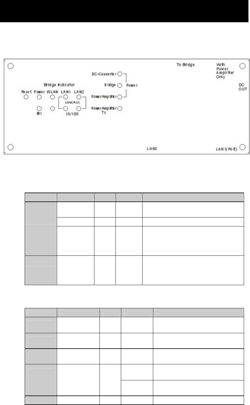
2.1.1 Panel of DC-Converter
Figure 2-1 DC-Converter
DC-Converter Indicator:
Function
LED Color
Status Description
DC-Converter
Green
On Power has being applied to
DC-Converter.
Bridge Green
On Power has being sent from DC OUT.
POWER
Power
Amplifier Green
On
Power has being applied to Power
Amplifier. Only functionally when the
Power Amplifier has been set into this
device.
Tx Power
Amplifier Tx
Red Blinking
Data has been sent via Power
Amplifier. Only functionally when the
Power Amplifier has been set into this
device.
Table 2-1
Bridge Indicator:
LED Function Color
Status Description
POWER
Power
indication Green
On Power has being applied to this
product.
M1 System status
Red Blinking
This product is functioning
properly.
WLAN Wireless
activity Green
Blinking
Sending or receiving data via
wireless.
On An active station is connected to
the corresponding LAN port.
LAN1
LAN2
Link/Act.
Link status Green
Blinking
The corresponding LAN port is
sending or receiving data.
10/100 Data Rate Green
On Data is transmitting in 100Mbps
7
LED Function Color
Status Description
on the corresponding LAN port.
Table 2-2
Port:
Port Description
RESET
To reset system settings to factory defaults, please follow the steps:
1. Power off the device,
2. Press the reset button and hold,
3. Power on the device,
4. Keep the button pressed about 5 seconds,
5. Release the button,
6. Watch the M1 LED, it will flash 8 times and then M1 flash once per
second.
To Bridge Two ports (LAN1and LAN2) connect with the bridge module board.
Refer to the 2.1.3 Side Panel of Bridge for more detail.
With Power
Amplifier
Only
This item include two sub-items (To Power Amplifier and To Bridge)
only use in when the power amplifier has been used. Refer to the 2.1.2
Side Panel of DC-Converter for more detail.
DC OUT DC connector transmits 12 voltage power which connects with DC-IN
in the side panel of bridge.
LAN1 (PoE)
LAN port connects to the DC-Injector which uses PoE (Power over
Ethernet) technology. This port has the physical connection to the
LAN1 port which locates in the side panel of DC-Converter.
LAN2 LAN port uses to connect to the other bridge has the physical
connection to the LAN2 port which locates in the side panel of
DC-Converter. Table 2-3
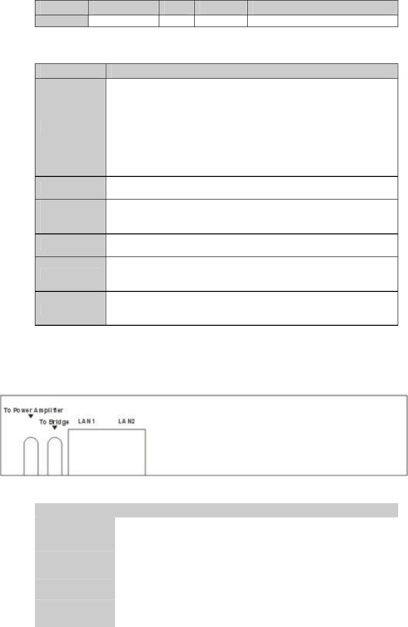
2.1.2 Side Panel of DC-Converter
Figure 2-2 Side Panel of DC-Converter
Port Description
To Power
Amplifier Connects to the power amplifier use the SMA to SMA cable.
To Bridge Connects to the Bridge’s module board use the SMA to SMA cable.
LAN1 Connects to the LAN1 port which locates in the side panel of bridge.
LAN2 Connects to the LAN2 port which locates in the side panel of bridge.
Table 2-4
8
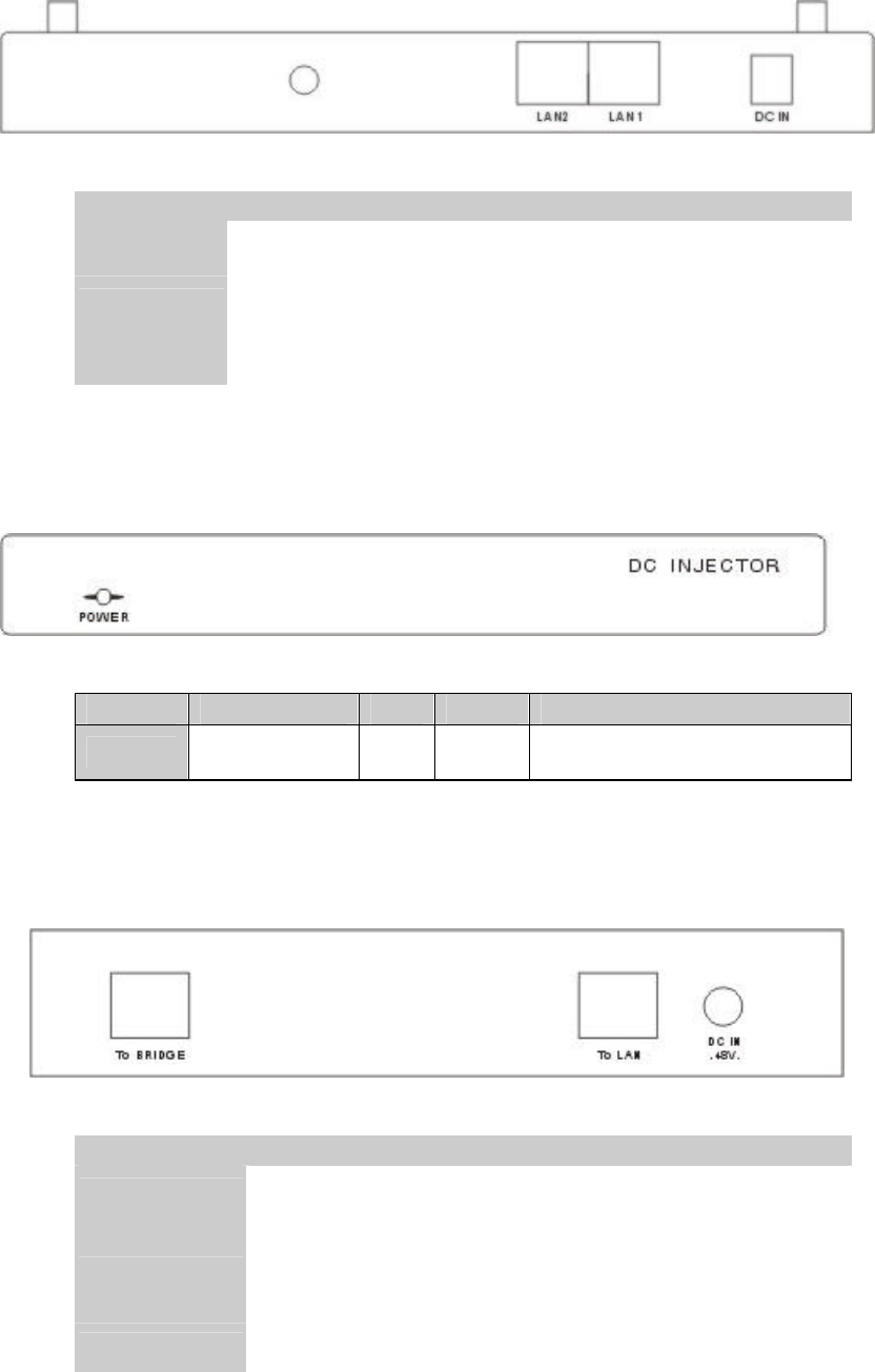
2.1.3 Side Panel of Bridge
Figure 2-3 Side Panel of Bridge
Port Description
DC IN DC connector comes with 12 voltage power which connects with DC-
out
in the DC-Converter.
LAN1 Connects to the LAN1 port which locates in the side panel of
DC-converter.
LAN2 Connects to the LAN2 port which locates in the side panel of side panel
of DC-converter.
Table 2-5
2.1.4 Front Panel of DC-Injector
Figure 2-4 Front Panel of DC-Injector
LED Function Color
Status Description
POWER
Power indication
Green
On Power has being applied to this
product.
Table 2-6
2.1.5 Rear Panel of DC-Injector
Figure 2-5 Rear Panel of DC-Injector
Port Description
DC IN 48V Connects with a power code which attached by the package.
To LAN
Connects to the existed network. The cable connection should be
straight Ethernet when connect this unit to the HUB/SWITCH and the
crossed cable when connect it directly to a PC Network Interface Card
(NIC).
To Bridge Connects to the DC-Converter’s LAN1 (PoE) port.
Table 2-7
9
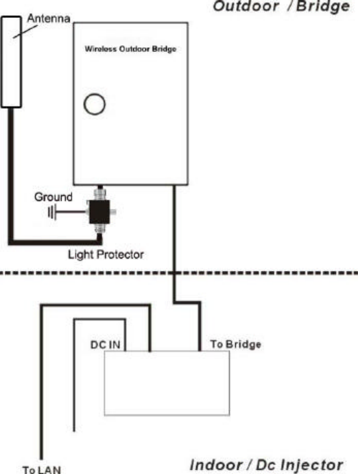
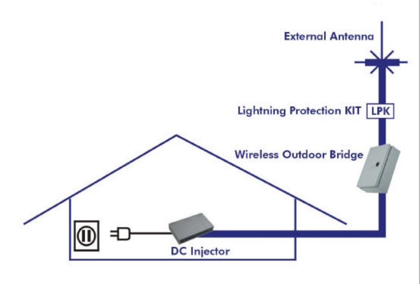
2.2 Procedure of Hardware Installation
Figure 2-6
1. Decide how to place Bridge
Because this product is a radio device works in the 2.4 GHz frequency
range. For optimum utilization, installing this product away from microwave
ovens or other devices, operating in the 2.4 GHz frequency range, which can
cause signal interference. Otherwise, install this product’s antenna in an area
where the trees, buildings and large steel structures such as file cabinet and
bookshelves do not obstruct the signal to and from the antenna. In conclusion,
the antenna should be located in the higher direct line-of-sight space.
2. Lightning Protection
Radio transmitters, receivers and RF cables require protection when
attacked by lightning strikes.
The surge protectors contain fast response gas filled arrestors to provide
low let through voltage for fast rise time transients. The device is configured
to minimize circuit capacitance and the performance can be assured up to
2GHz. Standard models provide protection for receivers and transmitters up to
a 1KW power level.
Installing this device in outdoor may be subject to lightning strikes. To
properly protect your equipment, you should install the lightning arrestor to
10
prevent an electrical surge from traveling through the antenna cable and into
the building. Lightning protection for a building is more forgiving than
protection of electrical devices. A building can withstand up to 100,000 volts,
but electrical equipment may be damaged by just a few volts.
Direct earth grounding of the antenna and the Lightning Protector is
necessary to protect the installation from lightning and the build-up of static
electricity.
The ground terminal is located on the lightning protector that attached with
this unit. Connect one end of the grounding cable to the Ground terminal and
the other end to a good ground connection.
The package content contains a lightning arrestor, and should be installed
and grounded at the point where the cable enters the antenna.
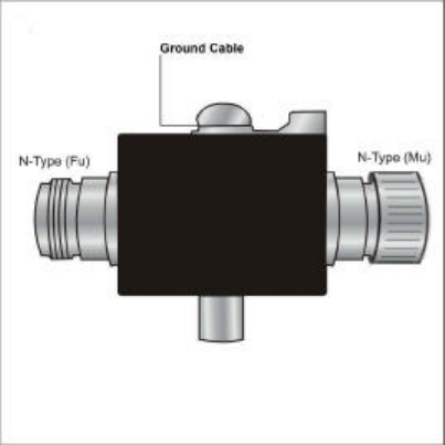
3. Connect the Antenna and Lightning Protector
The bridge connects to a Lightning Protector directly and the Lightning
Protector connects to the outdoor antenna with a standard N(Mu)-N(Mu) type
low-loss cable. A longer cable may decrease the distance achievable between
antennas.
The picture of lightning protector is shown in Figure 2-7.
4. Antenna Mast Requirements
To accommodate the outdoor antennas, the antenna mast must satisfy the
following requirements:
Ÿ The construction of the mast must be of a sturdy, weatherproof and no
corrosive material like for example galvanized or stainless steel construction
pipe.
Ÿ Typical diameter of the mast should be between 35 mm (1.4 in.) and 41 mm
(1.625 in.). Subject to the type of antenna that you intend to install other
diameters may be possible as well.
Ÿ The height of the antenna mast must be sufficient to allow the antenna to be
installed at least 1.5 m (5 ft.) above the peak of roof. If the roof is metal,
then the height of the antenna should be a minimum of 3 m (10 ft) above the
roof.
Ÿ The mast or wall-bracket must be free from any substance that may prevent
a good electrical connection with the antenna; for example, paint.
5. Connecting the Ground Wire
Direct earth grounding of the antenna and the Lightning Protector is
necessary to protect the installation from lightning and the build-up of static
electricity.
The Ground terminal is located on the lightning protector that attached
with this unit as shown in Figure 2-7. Connect one end of the grounding cable
to the Ground terminal and the other end to a good ground connection.
11
Figure 2-7 Lightning Protector
6. Connect the Ethernet and Power Cable
Ÿ Connect the power code to the DC-IN port on the rear panel of the
DC-Injector.
Ÿ Connect an Ethernet cable to the RJ-45 port (To LAN) on the rear
panel of the DC-Injector. Use the straight cable to connect to the
HUB/SWITCHA or use the crossed cable to connect to the PC’s
Network Interface Card (NIC).
Ÿ Connect an Ethernet cable to the other RJ-45 port (To Bridge) on the
rear panel of the DC-Injector and connect the other end to the LAN1
(PoE) port on the side of DC-Converter.
12
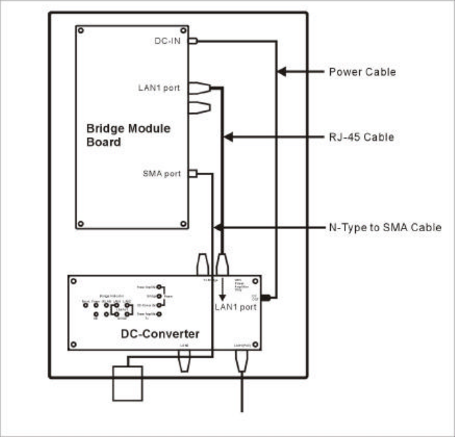
7. The Internal Connection of Bridge
a. Without Power Amplifier
Figure 2-8 Internal Construction without Power Amplifier
Ÿ Connect DC-OUT of the DC-Converter to DC-IN which locates in the
side panel of the Bridge Module Board with a Power Cable (320mm).
Ÿ Connect DC-Converter and Bridge Module Board on each LAN1 port
with a RJ-45 Cable.
Ÿ Connect the N-Type(Fu) to SMA(Mu) Cable to the SMA port (Fu)
which locates in the side panel of the Bridge Module Board.
13
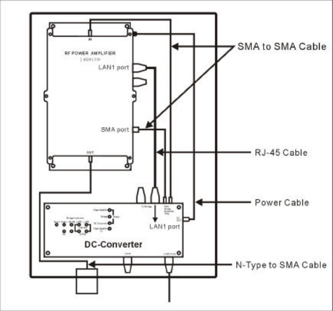
b. With Power Amplifier Inside
Figure 2-9 Internal Construction with Power Amplifier
Ÿ Connect the SMA port (Fu) of the DC-Converter (To Power Amplifier)
to the SMA port (Fu) of the Power Amplifier (IN) with a longer SMA
(Mu) to SMA (Mu) Cable (330mm).
Ÿ Connect the SMA port (Fu) of the Bridge Module Board (Under the
Power Amplifier) to DC-Converter (To Bridge) with a shorter SMA
(Mu) to SMA (Mu) Cable (100mm).
Ÿ Connect DC-Converter and Bridge Module Board on each LAN1 port
with a RJ-45 Cable.
Ÿ Connect DC-OUT of the DC-Converter to DC-IN which locates in the
side panel of the Bridge Module Board with a Power Cable (320mm).
Ÿ Connect the N-Type (Fu) to SMA (Mu) Cable to the SMA Out port
(Mu) which locates in the bottom of the power amplifier.
14
Without Additional DC-Injector
Figure 2-11
15
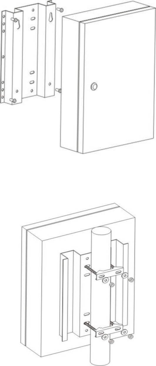
8. Installing the Outdoor Bridge
a. Mounting Bracket on the wall
Figure 2-13
b. Mounting Bracket on the Mast with the U-blots
The mast must (not provided) be constructed of sturdy, weatherproof, no
corrosive material such as galvanized or stainless steel construction pipe.
Figure 2-14
16
9. Connect to the other Bridge
For some special reasons, you may need to install two bridges as a
wireless repeater to lengthen the coverage range. Connect two bridges using a
crossed cable and plug into the LAN2 port in the side panel of the
DC-Converter as shown in Figure 2-2. Refer to the Chapter 3.3 for creating
two of Bridges as a wireless repeater.
10. Antenna Alignment
In case Bridge A is connecting with network IP 192.168.123.100. Bridge
B is connecting with network IP 192.168.123.101.
1. Figure out the rough direction/ location for both of the communication
stations A and B by map finding or by experience in using GPS/
compass/ telescope first!!
2. Connect both station stations A and B, roughly fix the Antenna and
pointing to the station direction for each other.
3. In DOS Mode, Ping A computer to B computer. (command:ping
192.168.123.101 –t ).
4. Stay B ANT. in the same direction, Fine tune A Antenna only with small
angle (less than 5 degree) in up/down/right/left direction, please check
the result of IP being ping, make sure the system in linking condition as
well as the time out possibility and response time as low as possible, if
the system been tuned to this condition, it is time to fix the A Antenna.
5. If the A Antenna has been fixed, please tune and fix the B Antenna
according to procedure 4. (Command for B computer to Ping A
computer: ping 192.168.123.100 –t).
6. If the link quality and the signal strength not in reasonable performance,
please repeat step 4 and 5 until optimum condition.
17
Chapter 3 Create a Bridge Network Environment
3.1 Bridge Configuration
1. Login this device with the administrator’s password as “admin” (default).
2. Select Primary Setup.
3. In the Primary Setup page, make sure the Mode is Bridge.
4. Enter the address into IP Address field which is in the same subnet with your
network environment.
5. Set the “Channel” and “SSID” of this device and another one which you want
to connect in the same channel and SSID.
6. Save the settings above and then reboot this device.
Figure 3-1
3.2 Create a Bridge Network Environment
The bridge supports external gain antennas with omni-directional or directional
capabilities. Omni-directional antennas are suited for systems requiring a signal
distribution in more than one direction. High-gain directional antennas are best suited
for longer coverage range in a fixed direction.
Due to the differences in placement and physical environment, every network
application has their unique installation. Before installing multiple bridges, you
should implement a testing of each site to determine the optimum networking
components and to maximize coverage range and network performance.
Think about the operating and environmental conditions of following when
implement this testing:
18
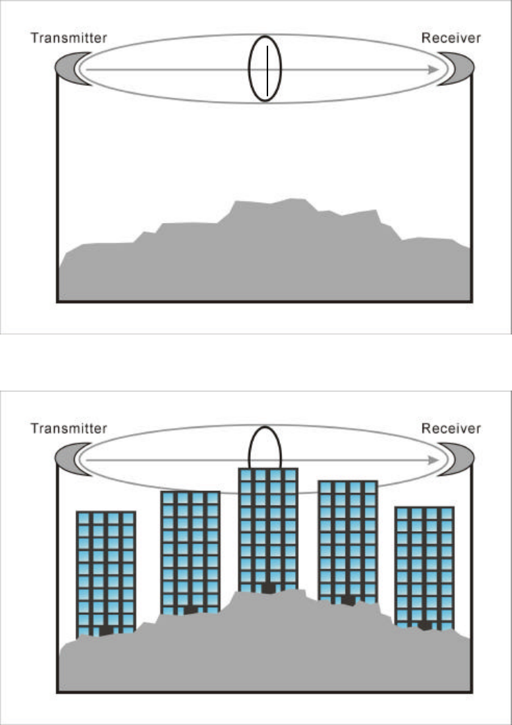
1. Multipath propagation
Transmitted signals can combine with reflected ones to corrupt the signal
detected by the receiver. The PATH between two antennas is a straight line as
shown in Figure 3-2. Any obstacle in this PATH can redirect parts of the
transmitted signal as shown in Figure 3-3. The best propagation path is a clear
line of sight with good clearance between the PATH and any physical obstacle.
Figure 3-2
Figure 3-3
Clearance
19
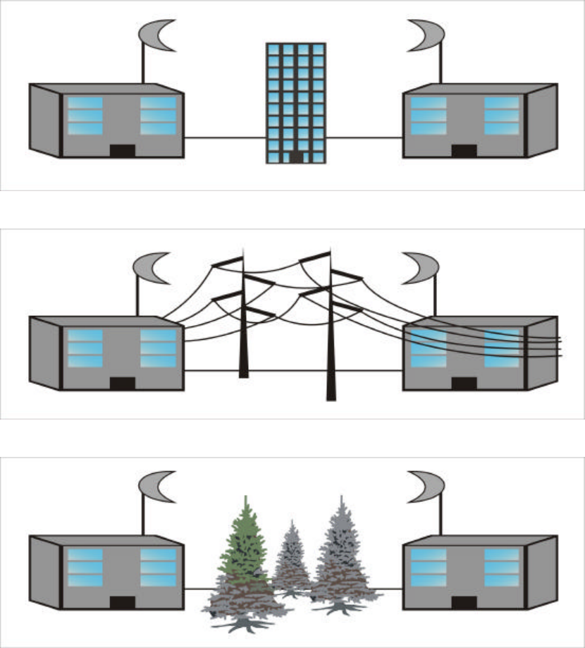
2. Path loss
Path loss between the transmitter and receiver is a key consideration when
designing a wireless LAN solution. Expected levels of path loss, based on the
range between the transmitter and receiver, provide valuable information when
determining requirements for transmit power levels, receiver sensitivity and
signal-to-noise ratio. Actual path loss depends on the transmit frequency, and it
grows exponentially as the distance increases between the transmitter and receiver.
In addition, path loss is minimized when there exists a clear line of sight and is
lower when antennas are positioned higher. Refer to the potential obstacles to
Line of Sight as shown in Figure 3-4, Figure 3-5 and Figure 3-6.
Figure 3-4
Figure 3-5
Figure 3-6
20
3. Physical environment and Obstructions
Open areas provide better coverage range than closed areas. Also, the
obstructer such as steel buildings or trees can block or decrease communication
between bridges. To avoid this situation, the antennas should be located in where
is no or few obstruction between the sending and receiving antennas.
4. Rooftop Installation
Rooftop installations offer several advantages such as Fewer obstacles in
path, Increasing the range of antenna, reducing multipath problems and
Improving performance due to greater height. But please notice that Rooftop
Installations are extremely dangerous! Incorrect installation way may cause in
serious injury or death. Such installations should be performed by the professional
installer.
5. Throughput of Data
Coverage range is inversely proportional to data rates. The maximum radio
range is achieved at the lowest workable data throughput.
21
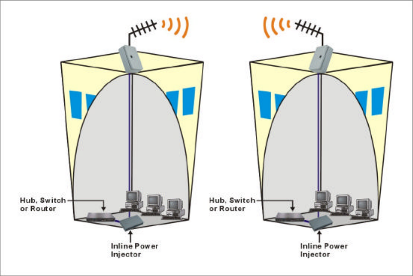
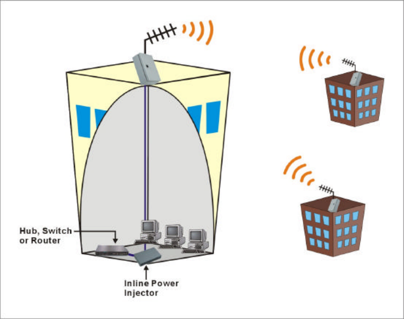
3.3 Connect Buildings by using Bridges
Wireless point-to-point networks use technologies very similar to wireless
LANs. A radio-based wireless point-to-point network as shown in Figure 3-7 and
Figure 3-8 is currently the most common method for providing connectivity
within a metropolitan area. All of these bridges have to use highly directional
antennas to focus the signal power in a narrow beam, in order to maximizing the
transmission distance. The actual transmission distance of a particular product,
depends on environment conditions and terrain. Rain, for example, causes
resistance to the propagation of radio signals, decreasing the effective range. A
mountainous area will also hamper the transmission range of the signals. Refer to
Chapter 3.2 for determining how to set up the wireless bridge environment.
3.3.1 Point to Point Configuration
In point-to-point configuration, a pair of bridges is set up to communicate only
with each other. In a typical point-to-point application, the bridge acts as a data
channel, providing a wireless link between sites separated by considerable
distances. Actual distance attained depends on the antennas used and their
installation. Both voice and data can be transmitted between sites.
Figure 3-7
22
Figure 3-8
23
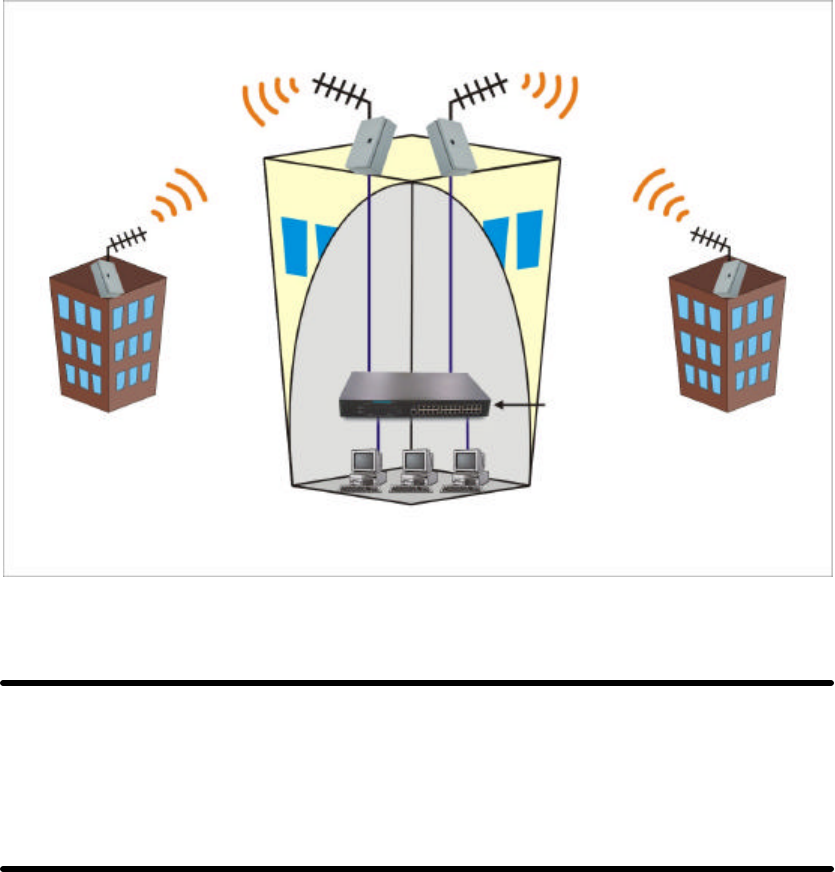
3.3.2 Repeater Configuration
The repeater configuration extends maximum communication range beyond
the radio horizon. An additional pair of bridges is set up at an intermediate site,
one oriented towards each of the end points. Transmissions from one end point are
received by the intermediate bridge facing it, passed by wire to the other
intermediate bridge, and retransmitted to the other end point. This configuration
normally requires directional antennas for maximum range.
Figure 3-9
NOTE: To minimize the influence of obstacles, signal interference or reflections,
install the antennas at least 2 meters (6 feet) away from all other antennas. Use
the straight cable (RJ-45) to connect to the HUB/SWITCHA or use the crossed
cable to connect to the PC’s Network Interface Card (NIC).

24
Chapter 4 General Configuration
4.1 Log in and Start up
This product provides a web based configuration scheme, make possible to
configure by web browser such as Netscape Communicator or Internet Explorer.
1. Start the web browser, and disable the proxy or add the IP address of this
product into the exceptions of Proxy setting. Then, type this product’s IP
address (the default setting is 192.168.123.254) in the Location (for Netscape)
or Address (for IE) field and press ENTER.
2. You will see the web user interface after the connection is established. To log in
as an administrator, enter the system password (the default setting is” admin ”)
in the System Password field and click on the Log in button. If the password is
correct, the web appearance will change to Administrator’s Main Menu.
4.2 Inspect System Information
Check system information with click the System Info in Administrator’s Main
Menu.
A. Network ID (SSID): The current setting of SSID
B. Firmware Version: The current firmware version on this device
C. MAC Address: The MAC address of this device
D. Printer: The possible kinds of printer status include “Ready”, “Not ready”,
“Printing… ”, and “Device error”.
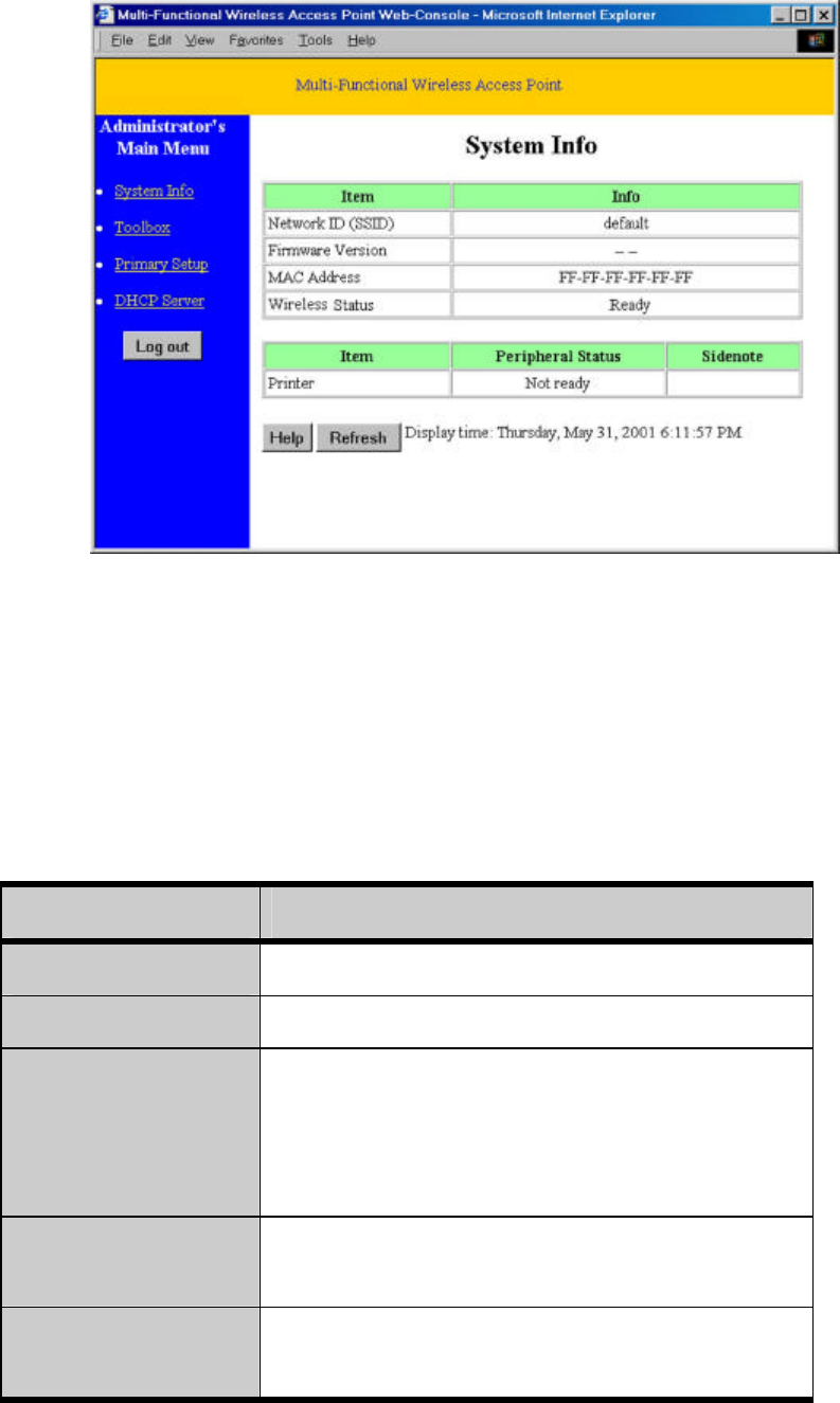
25
Figure 4.1
When this device is printing, there may appear a “Kill Job” button on the
Sidenote column. You can click this button to cancel the current printing job
manually.
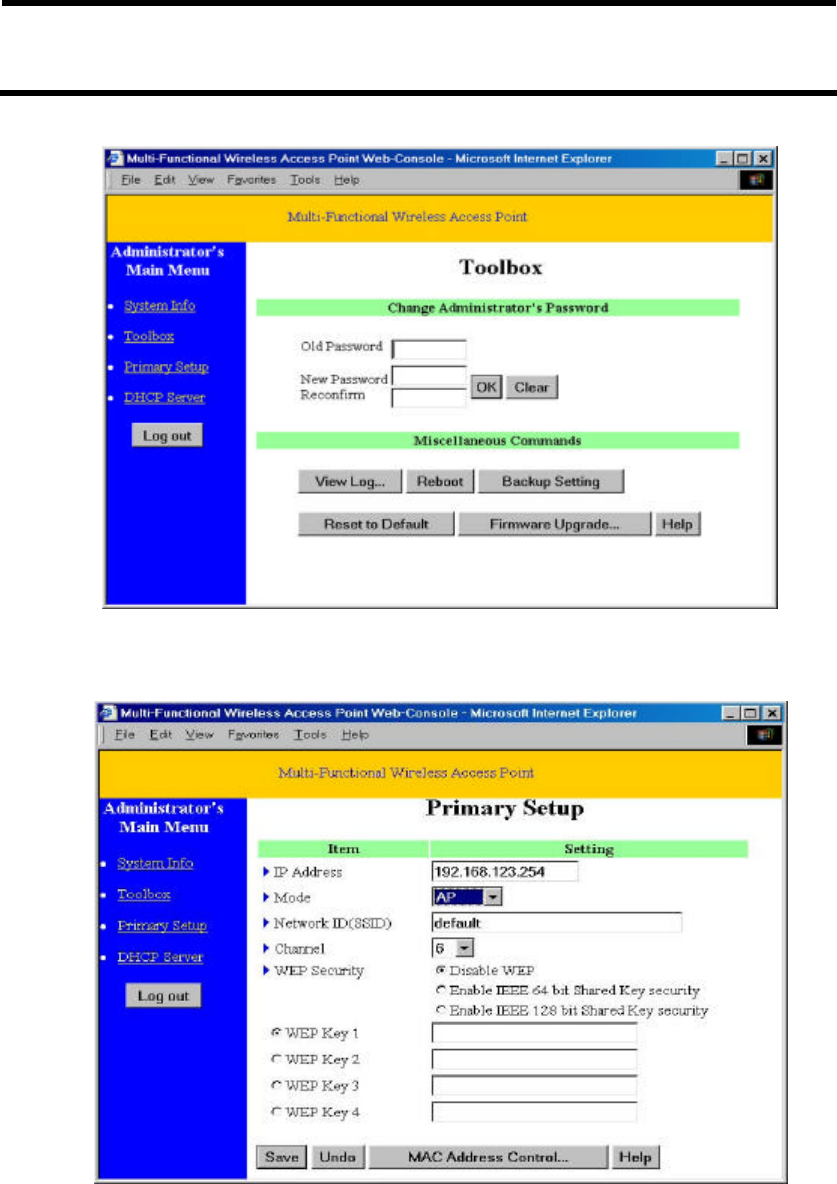
4.3 Tool Box
This option enables you to change the administrator password.
There are some useful buttons in this page:
Item Function
View Log View the system logs
Reboot Reboot this device
Backup Setting You can backup your settings by clicking this
button and save it as a bin file. Once you want to
restore these settings, please click Firmware
Upgrade button and use the bin file you saved
Reset to Default Reset the settings of this device to the default
values
Firmware Upgrade Prompt the administrator for a file and upgrade it to
this device
26
NOTE: we strongly recommend you to change the system password for security
reason.
Figure 4.2
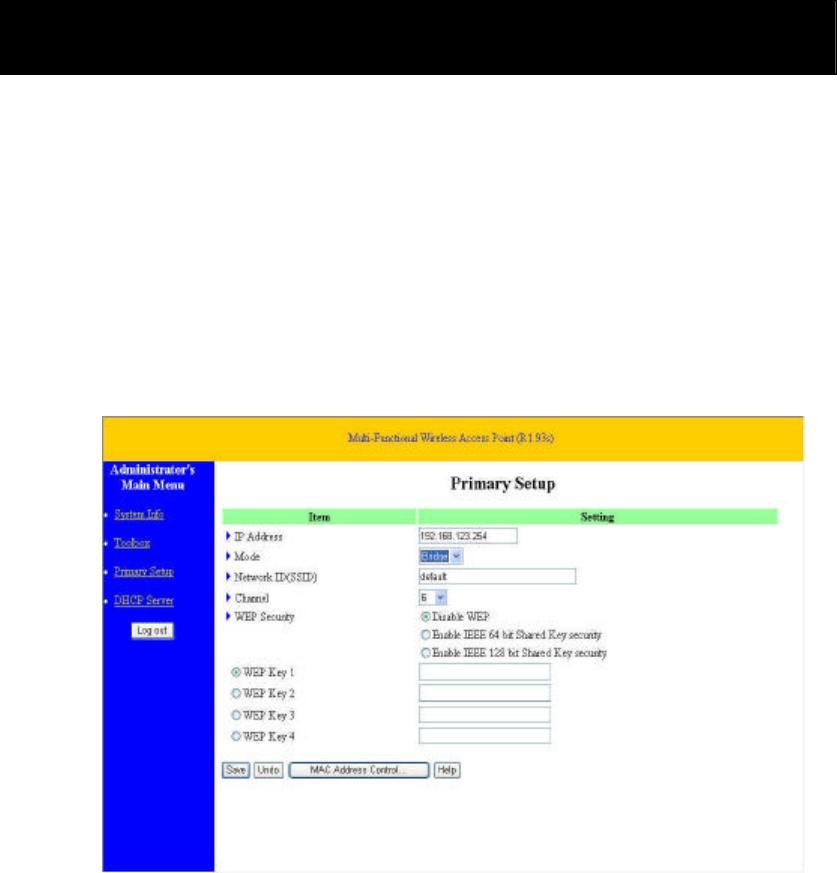
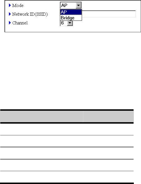
4.4 Primary Setup
Figure 4.3
This option is primary to enable this product to work properly.
1.IP Address: the IP address of this device.
2.Mode: the operating mode of this device. The default mode is “Bridge”, which
27
is the normal operation mode of a Bridge. Users can change it to the “AP”
mode if you want this product to work as a wireless access point.
Figure 4.4
3.Network ID (SSID): Network ID is used for identifying the Wireless LAN
(WLAN). Client stations can roam freely over this product and other Access
Points that have the same Network ID. (The factory setting is “default”).
Note: This item won’t take effect in “Bridge” mode.
4.Channel: The radio channel number. The permissible channels depend on the
Regulatory Domain.
The factory setting is as follows:
Countries Channel
USA/Canada 1 - 11
Europe/Australia (ETSI) 1 - 13
Japan (All) 1 -14
Singapore, France 10 - 13
Israel 3 - 8
5.WEP Security: Select the data privacy algorithm you want. Enabling the
security can protect your data while it is transferred from one station to
another. The standardized IEEE 802.11 WEP (64-bit or 128-bit) is used here.
6.WEP Key 1, 2, 3 & 4: After enable the 64-bit or 128-bit WEP key security,
please select one WEP key to be used in default setting and then input 10 or 26
hex-decimal (0-9, A-F) digits.
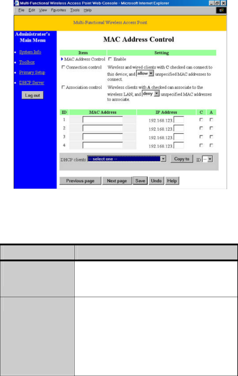
7.MAC Access Control: Setup MAC addresses to control which wireless
clients can associate to the wireless LAN and this device or connect to this
device.
28
Figure 4.5
MAC Address Control allows only client devices with specified MAC
addresses to associate and pass data through this device.
Item Function
MAC Address
Control
Check “Enable” to enable the “MAC Address
Control”. All of the settings in this page will take
effect only when “Enable” is checked.
Connection control Check "Connection control" to enable the controlling
of which wired and wireless clients can connect to
this device. If a client is denied to connect to this
device, it means the client can't access to the Internet
either. Choose "allow" or "deny" to allow or deny the
clients, whose MAC addresses are not in the "Control
table" (please see below), to connect to this device.

29
Association control Check "Association control" to enable the controlling
of which wireless client can associate to the wireless
LAN. If a client is denied to associate to the wireless
LAN, it means the client can't send or receive any data
via this device. Choose "allow" or "deny" to allow or
deny the clients, whose MAC addresses are not in the
"Control table", to associate to the wireless LAN.
Control table "Control table" is the table at the bottom of the "MAC
Address Control" page. Each row of this table
indicates the MAC address and the expected IP
address mapping of a client. There are four columns in
this table as shown in the below Table.
Item Function
MAC Address MAC address indicates a specific client.
IP Address Expected IP address of the corresponding
client. Keep it empty if you don't care its IP
address.
C When "Connection control" is checked,
check "C" will allow/deny the
corresponding client to connect to this
device.
A When "Association control" is checked,
check "A" will allow/deny the
corresponding client to associate to the
wireless LAN.
In this page, we provide the following Combobox and button to help users to
input the MAC address.
Figure 4.6
30
Select a specific client in the “DHCP clients” Combobox, and then click on the
“Copy to” button to copy the MAC address of the client you select to the ID selected
in the “ID” Combobox.
Previous page and Next Page To make this setup page simple and clear, we have
divided the “Control table” into several pages.
You can use these buttons to navigate to different
pages.

31
Chapter 5 System Troubleshooting
Problem and Indication Possible Solution/ Answer
What is this bridge’s default
IP Address?
This bridge’s default IP address is 192.168.123.254
I reset this bridge to factory
defaults but the IP address
hasn't changed.
Resetting this device to factory defaults does not
reset the device's IP address to 192.168.123.254
I can't exchange data over a
Point to- Point link.
Check the following steps:
1. Ensure that each device has the same Channel
and SSID.
2. Confirm that both devices have Bridge Mode
enable.
3. Make sure that all obstructions and possible
sources of interference were considered when
designing the path.
Lots collisions on my
network have increased
dramatically after I installed
this device?
If these devices in your installation have a poor
radio link, then this can increase the number of
collisions on the network. Improve the radio link
between each device to reduce the number of
collisions.
What antenna should I use
with this bridge?
This device does not ship with an antenna. You
should order an antenna additionally. Antenna
selection depends on the requirements of your
microwave path. Refer to the Table 3-1 to get the
recommendation of the antennas.
I can't ping a remote site
from across the wireless link.
This device is only valid over the Ethernet interface
and will not respond to ping requests from across
the radio link.
No Power to device, Power
LED is off.
1. Power cord is not properly connected. Please
verify power cord to connect to this device and to
the power outlet.
2. Power supply is defective. Please replace the
power supply.
Wireless link has established, 1. Check that the LINK LED is lighted Green. If

32
Problem and Indication Possible Solution/ Answer
but there is no Ethernet
activity.
this is not the case, the port is inactive. Try another
port on the hub or another UTP cable.
2. Ensure that Ethernet port in unit is working. Ping
this device to confirm Ethernet connection.
3. Verify that you are using a cross-over UTP cable
(pins 1 & 3, 2 & 6) if connected directly to
workstation, or a straight-through cable if
connected to a hub.
33
Appendix A TCP/IP Configuration for Windows
95/98/ME/2000/XP
This chapter will introduce how to install the TCP/IP protocol in the personal
computer and using the TCP/IP setting to connect this device correctly.
A.1 Configure Windows 95/98/ME Platforms for working with this
device
1. Connect this device to a computer by general network cable.
2. On the Windows 95/98/ME Platforms, click Start button and choose Settings,
then click Control Panel.
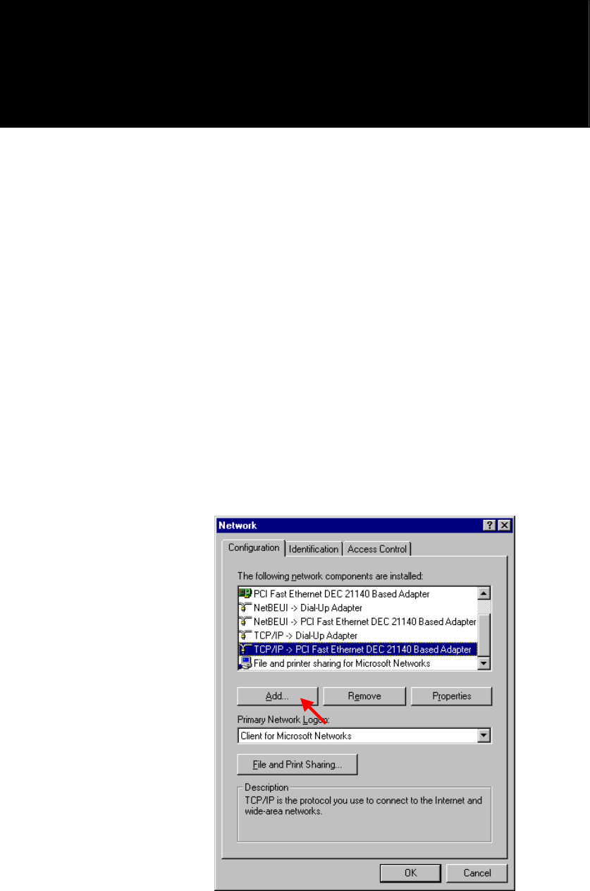
3. Double click Network icon and select Configuration tab in the Network
window.
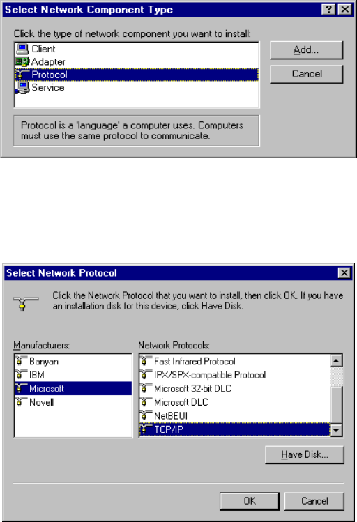
4. Click Add button to add network component into your PC.
34
5. Double click Protocol to add TCP/IP protocol.
6. Select Microsoft item in the manufactures list. Then choose TCP/IP in the
Network Protocols list. Click OK button to return to Network window.
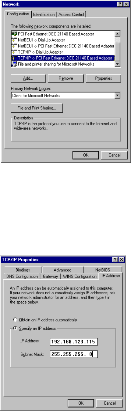
7. The TCP/IP protocol shall be listed in the Network window. Click OK to
complete the install procedure and restart your PC to enable the TCP/IP
protocol.
8. After rebooting, click Start button and choose Settings, then click Control
Panel.
9. Double click Network icon. Select the TCP/IP line that has been associated to
your network card in the Configuration tab of the Network window.
10. Click Properties button to set the TCP/IP protocol for this device.
35
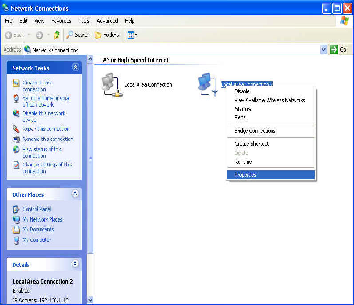
11. Select Specify an IP address in the IP Address tab. The default IP address of
this product is 192.168.123.254. So please use 192.168.123.xxx (xxx is
between 1 and 253) for IP Address field and 255.255.255.0 for Subnet Mask
field.
36
12. In the Gateway and DNS tab, do not put anything.
13. Click OK button to finish the TCP/IP setting and restart the computer.
37
A.2 Configure Windows 2000/XP Platforms for working with this
device
1. After complete installation the windows 2000/XP, the system will
automatically install the TCP/IP protocol.
2. Connect this device to a computer by general network cable.
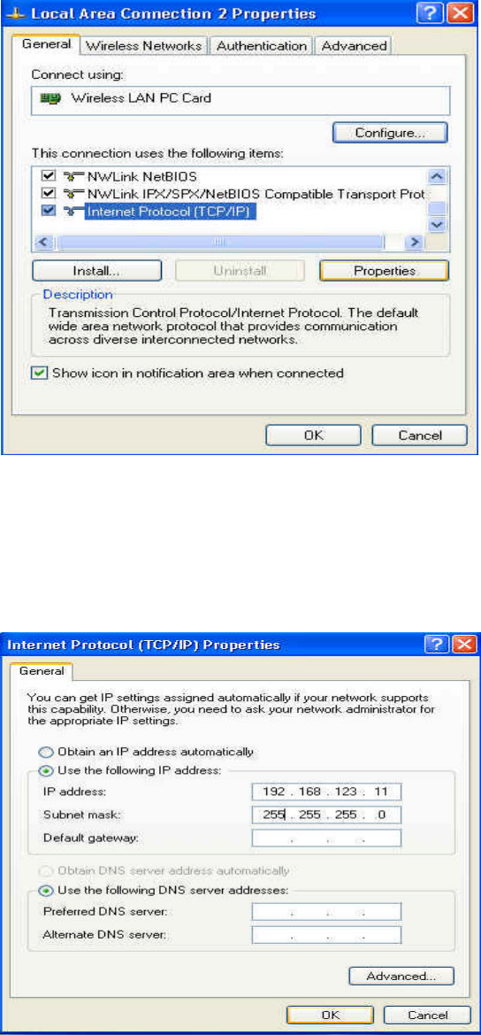
3. On the Windows 2000/XP platform, right click My Network Places on the
desktop then select Properties.
4. In the Network Connections dialogue window, right click the network
connection icon of Wireless LAN PC Card and select properties.
38
5. In the General tab, choose Internet Protocol (TCP/IP) and click the
properties button.
6. In the General tab, select Use the following IP address and set a IP address
which is in the same subnet with this product(default is 192.168.123.254).
7. Do not put anything in the Default gateway and DNS field.
Click the OK button to complete TCP/IP setting.

39
Appendix B Technical Specifications
General
Data Transfer Rate 11, 5.5, 2 and 1 Mbps, Auto Fall-Back
Range (open environment) 11 Mbps –300m/450m ( 23 dBm output
power)
5.5 Mbps –400m/600m ( 23 dBm output
power)
2 Mbps – 500m/750m ( 23 dBm output
power)
1 Mbps –800m/1200m ( 23 dBm output
power)
Antenna Connector N-Type
LED Indicator Power, Bridge and RF activity
WEP Data Encryption 64/128-bit
Regulation Certifications FCC Part 15/UL, ETSI 300/328/CE
Network
Interface Two 10/100Mbps RJ-45 Switch Port,
Security MAC address filtering
Management Web-based configuration
Radio
Frequency Band 2.400∼2.484 GHz
Radio Type Direct Sequence Spread Spectrum (DSSS)
Operation Channels 11 for North America, 14 for Japan,
13 for Europe, 2 for Spain, 4 for
France
Modulation 11 Mbps / 5.5 Mbps CCK;2 Mbps:
DQPSK;1 Mbps: DBPSK

40
Radio
RF Output Power 29.5dBm(891mW)--FCC
20dBm(100mW)--CE
Environment
Temperature Range 0 to 50° C (32 to 131 °F)-operating
-20 to 80 ° C(-4 to 176 °F) storage
Humidity (non-condensing) 5%∼95% typical
Physical Specifications
Dimensions 354(L)mm * 249(W)mm * 89(H)mm
13.9(L)in. * 9.8(L) in. * 3.5(H) in.
Weight 2.1Kg
Electrical
Power Supply Active Ethernet (power over
Ethernet) –48 VDC/0.7A
External Unit: Auto sensing 100/240
VAC; 50/60 Hz
Surge Arrester 20KA Surge Current