Senao Co 2511BGPLUS Wireless Outdoor Bridge User Manual RBmenu ch0
Senao International Co Ltd Wireless Outdoor Bridge RBmenu ch0
UserManual.wiki
>
Senao Co
>
2511BGPLUS User Manual
>
Manual
Contents
1.
Manual
2.
Revised Manual 2
Manual
Navigation menu
Upload a User Manual
Namespaces
Wiki Guide
HTML
PDF
Info
Views
User Manual
Discussion / Help
Navigation
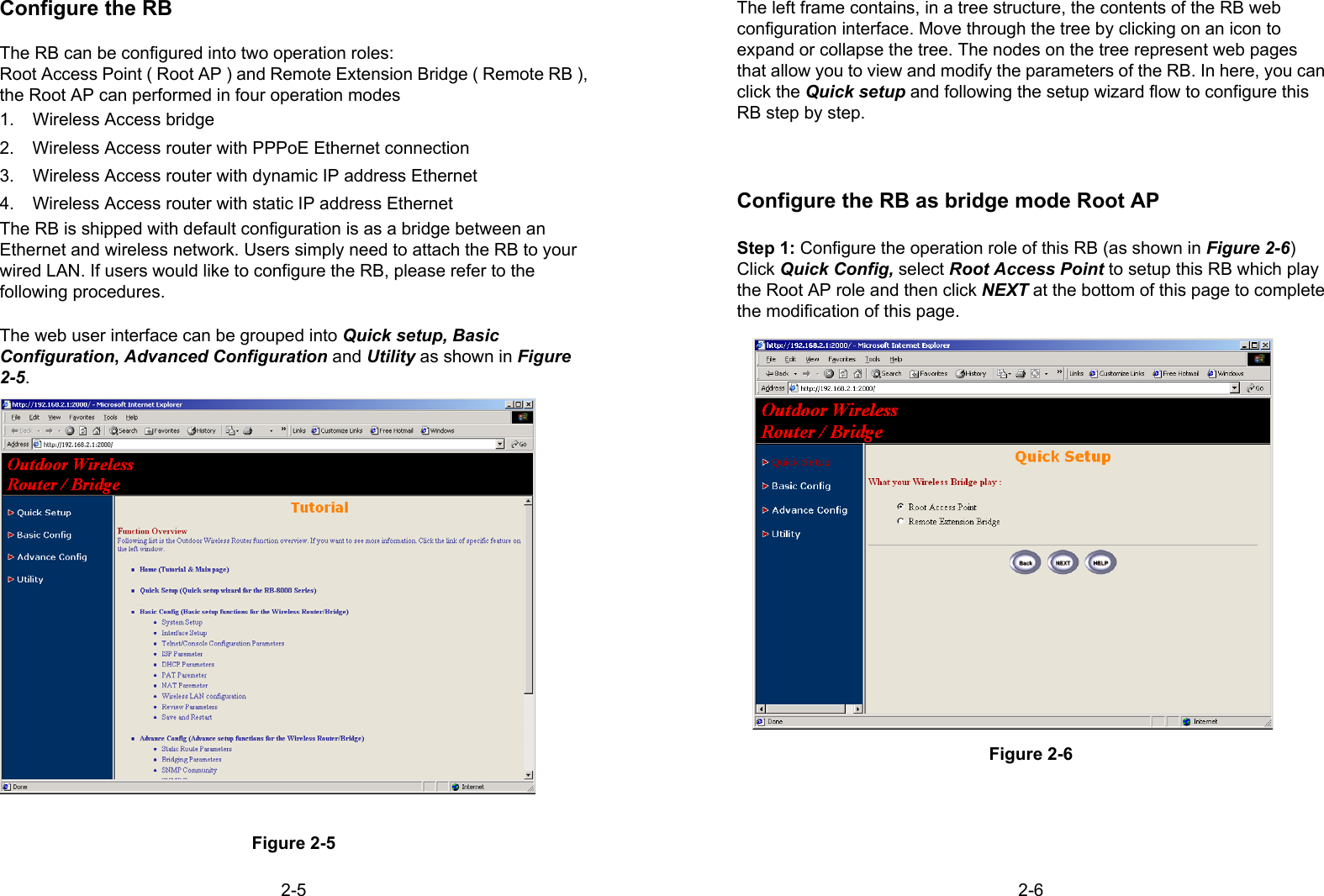
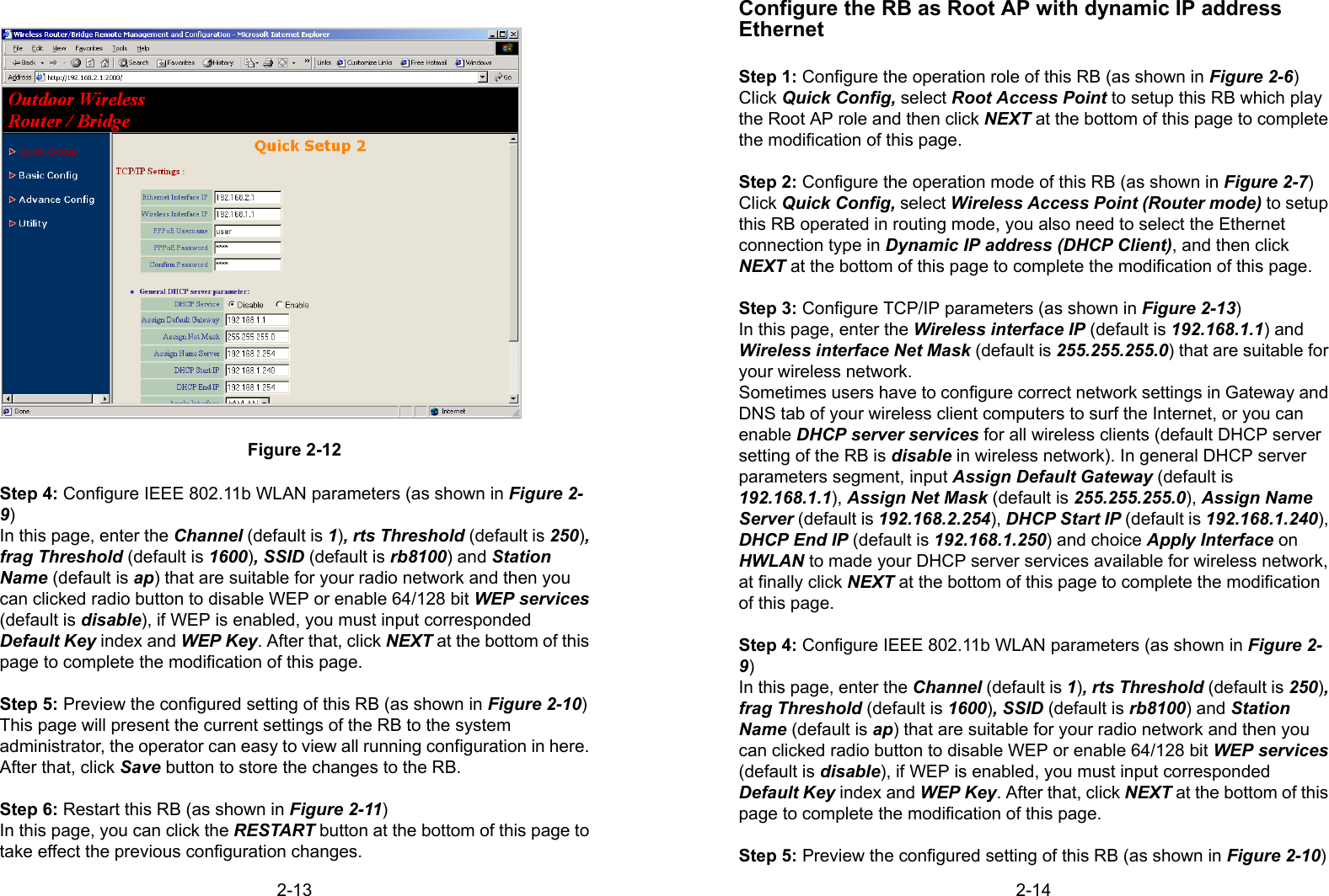
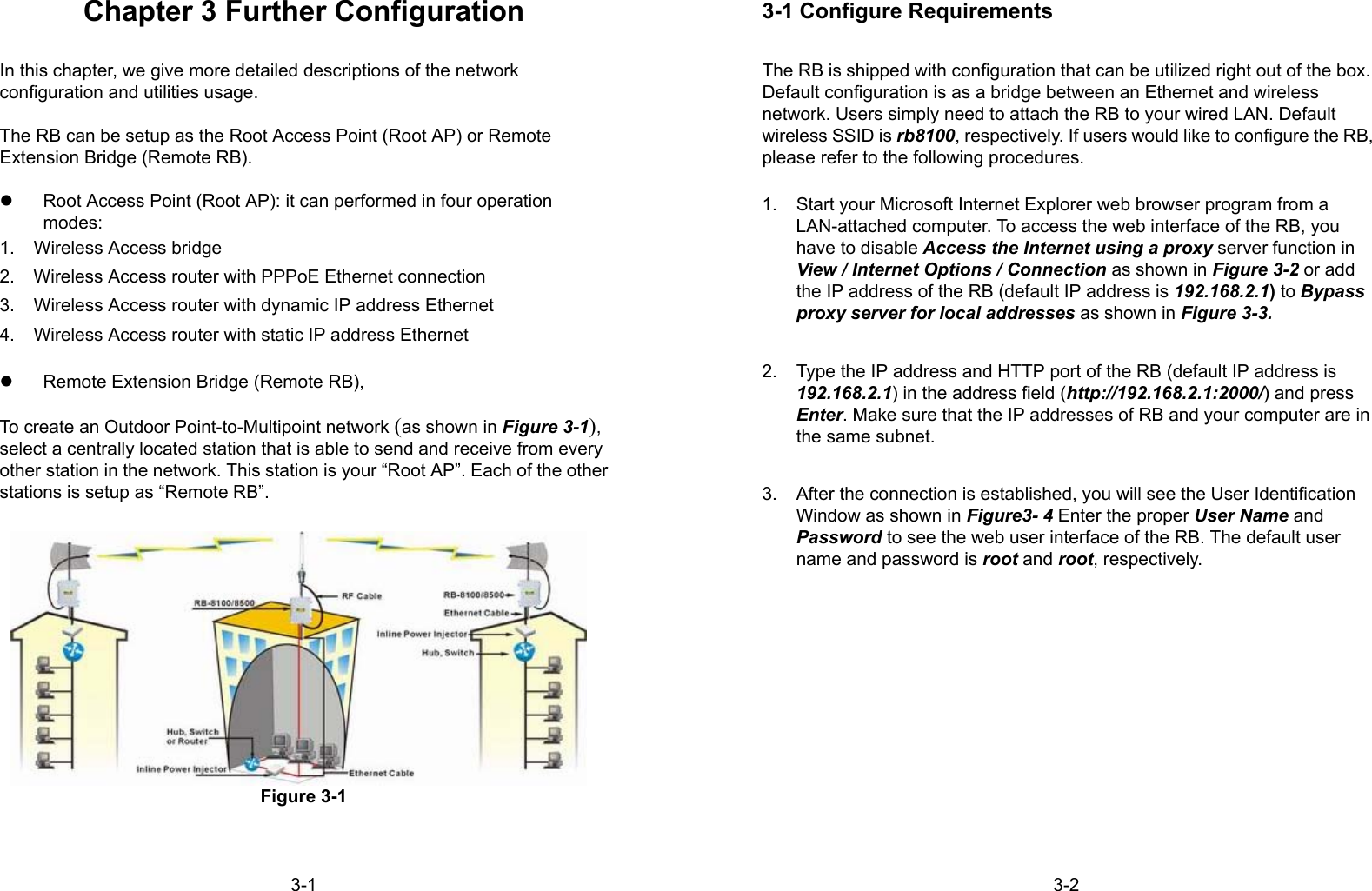
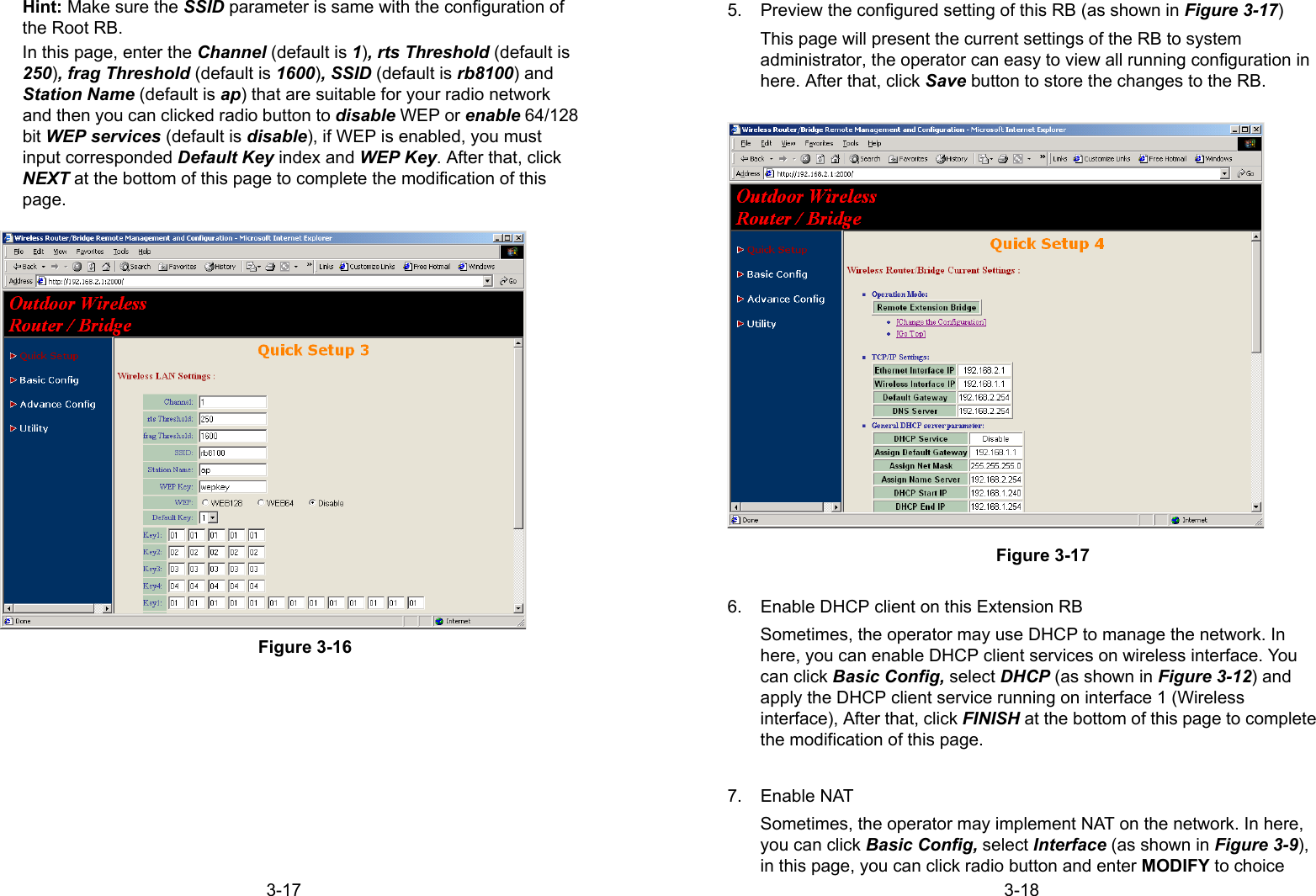

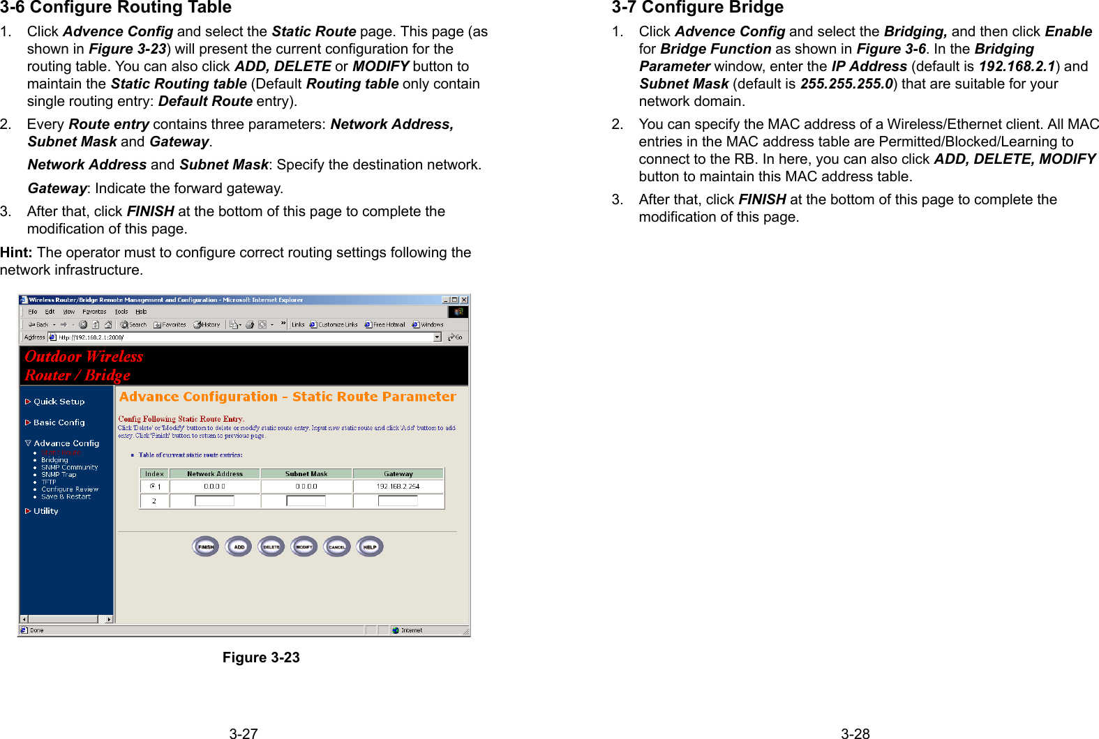
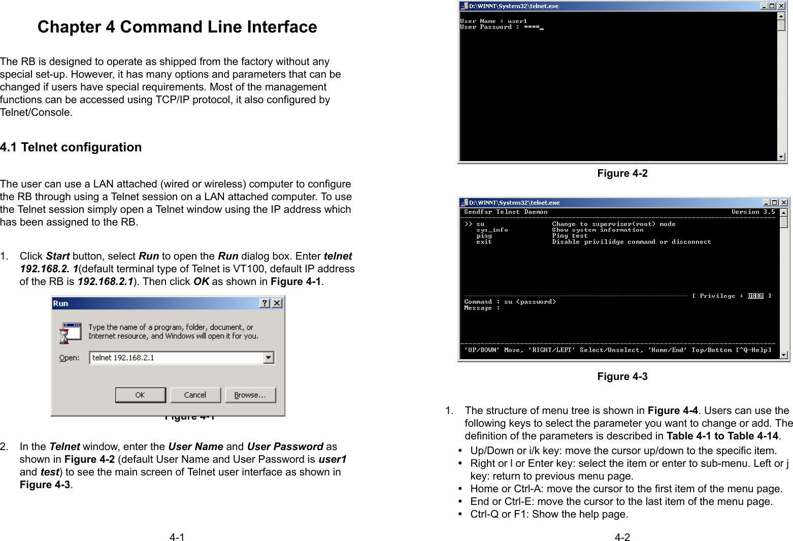
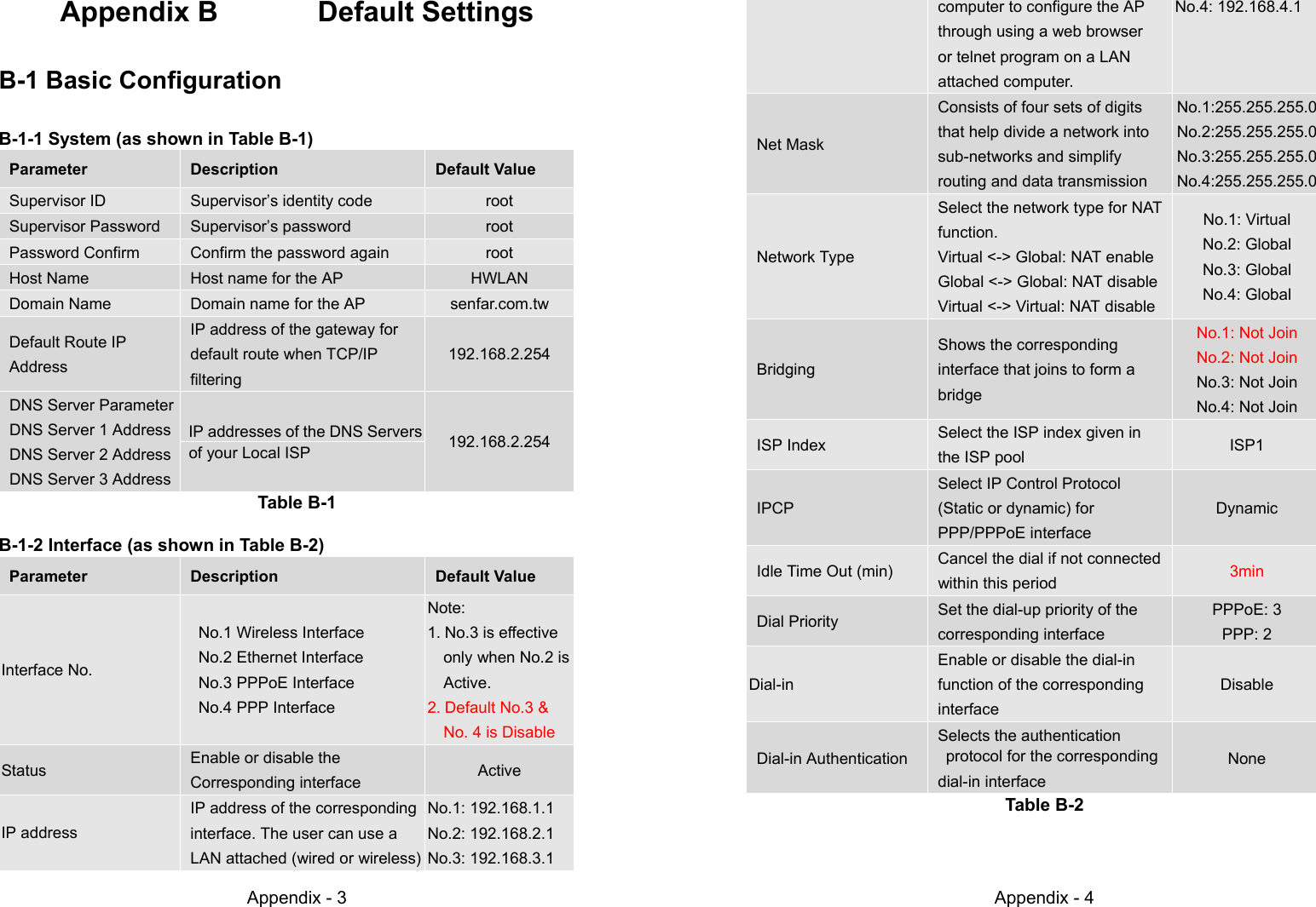
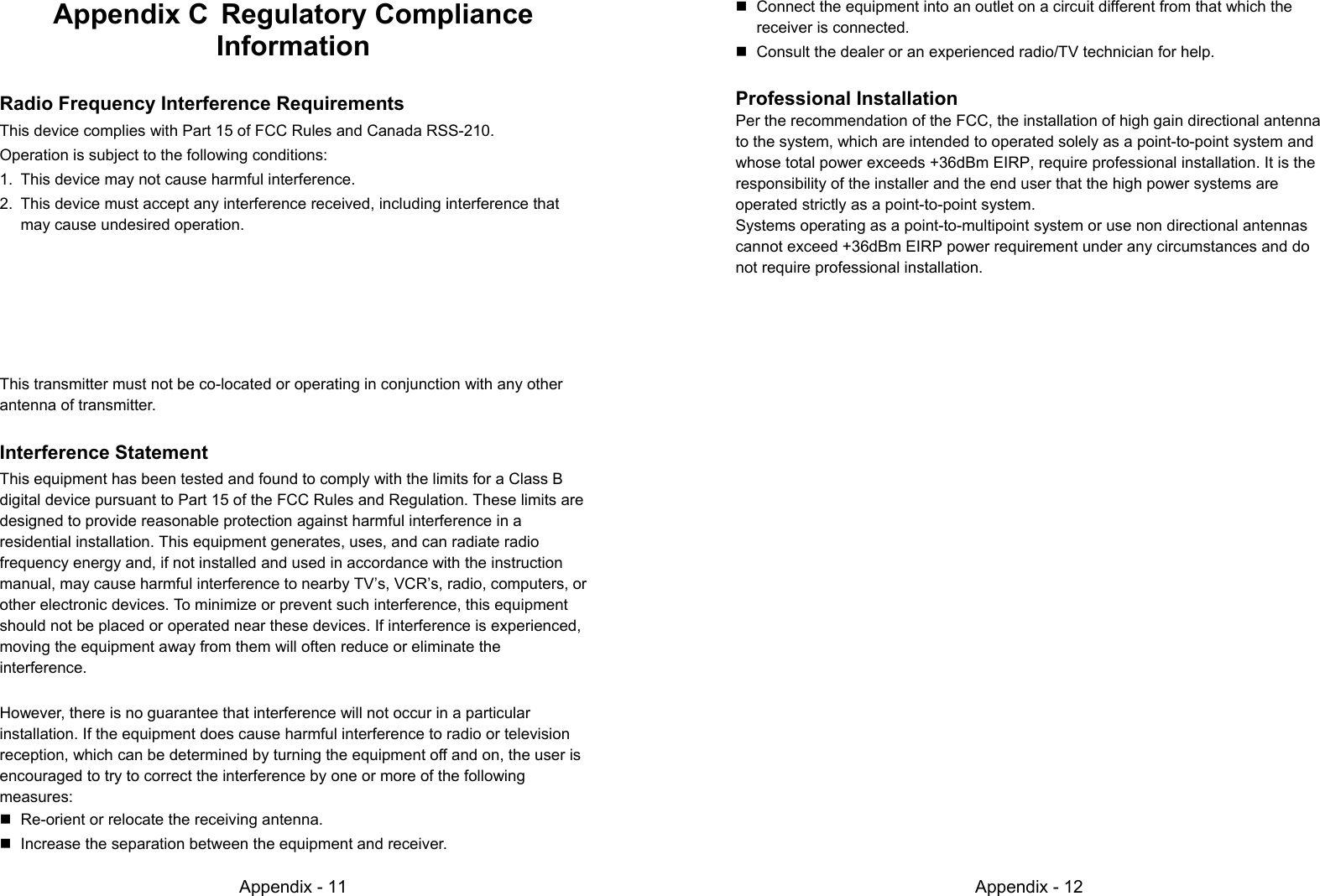
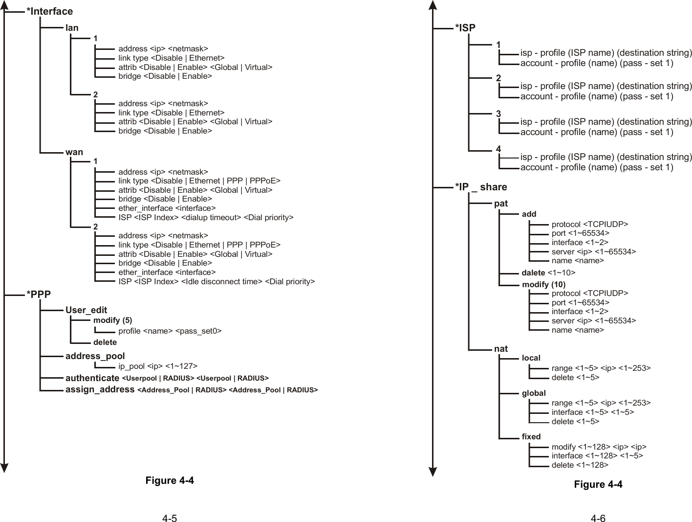
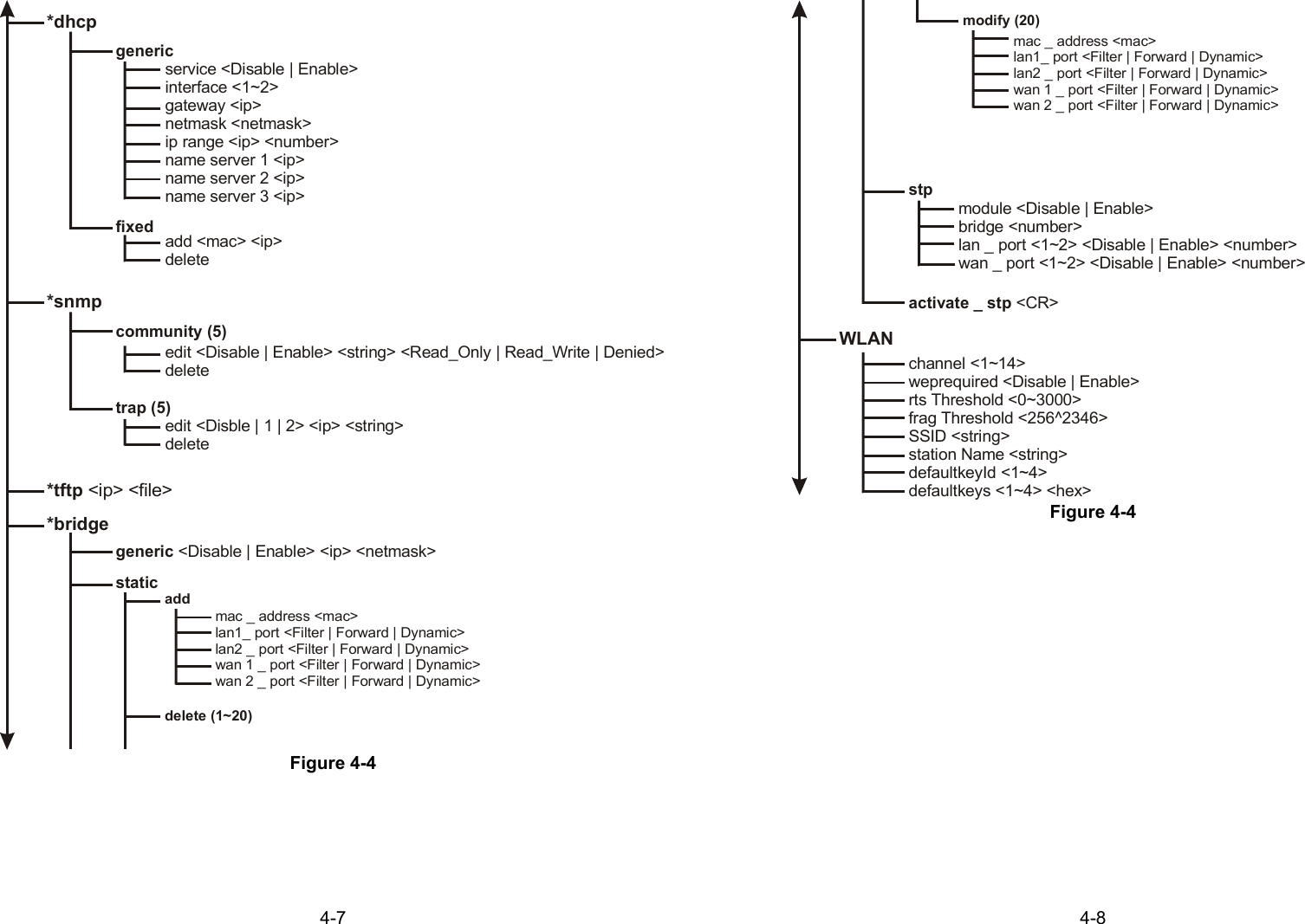
Passwd <pass_conf>*SystemOP _ mode <Router | Bridge | Host>hostname <name>default _ route <ip>PPPPeer_address <ip>User_profile <name> <pass_set0>](https://usermanual.wiki/Senao-Co/2511BGPLUS.Manual/User-Guide-267726-Page-34.png)
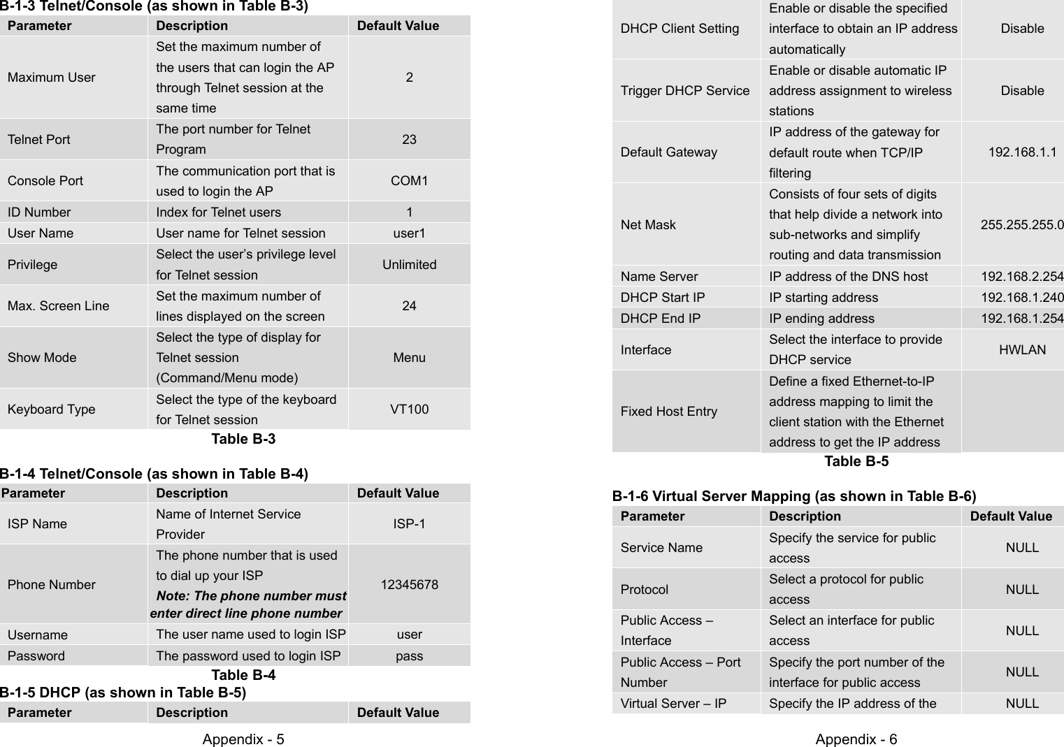
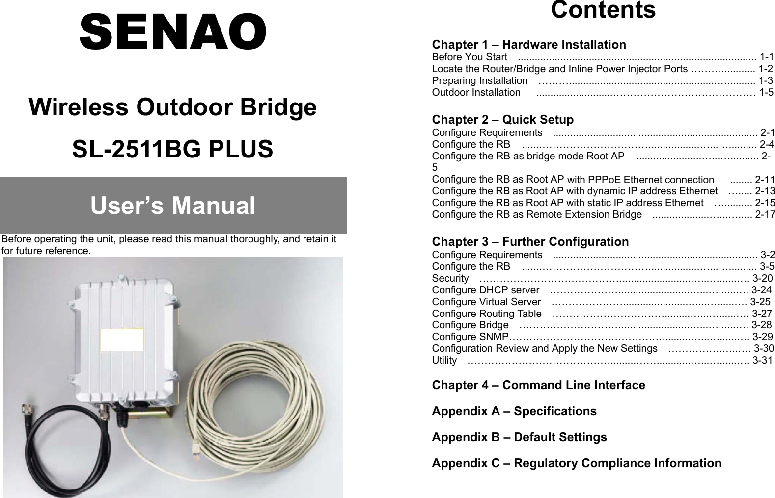
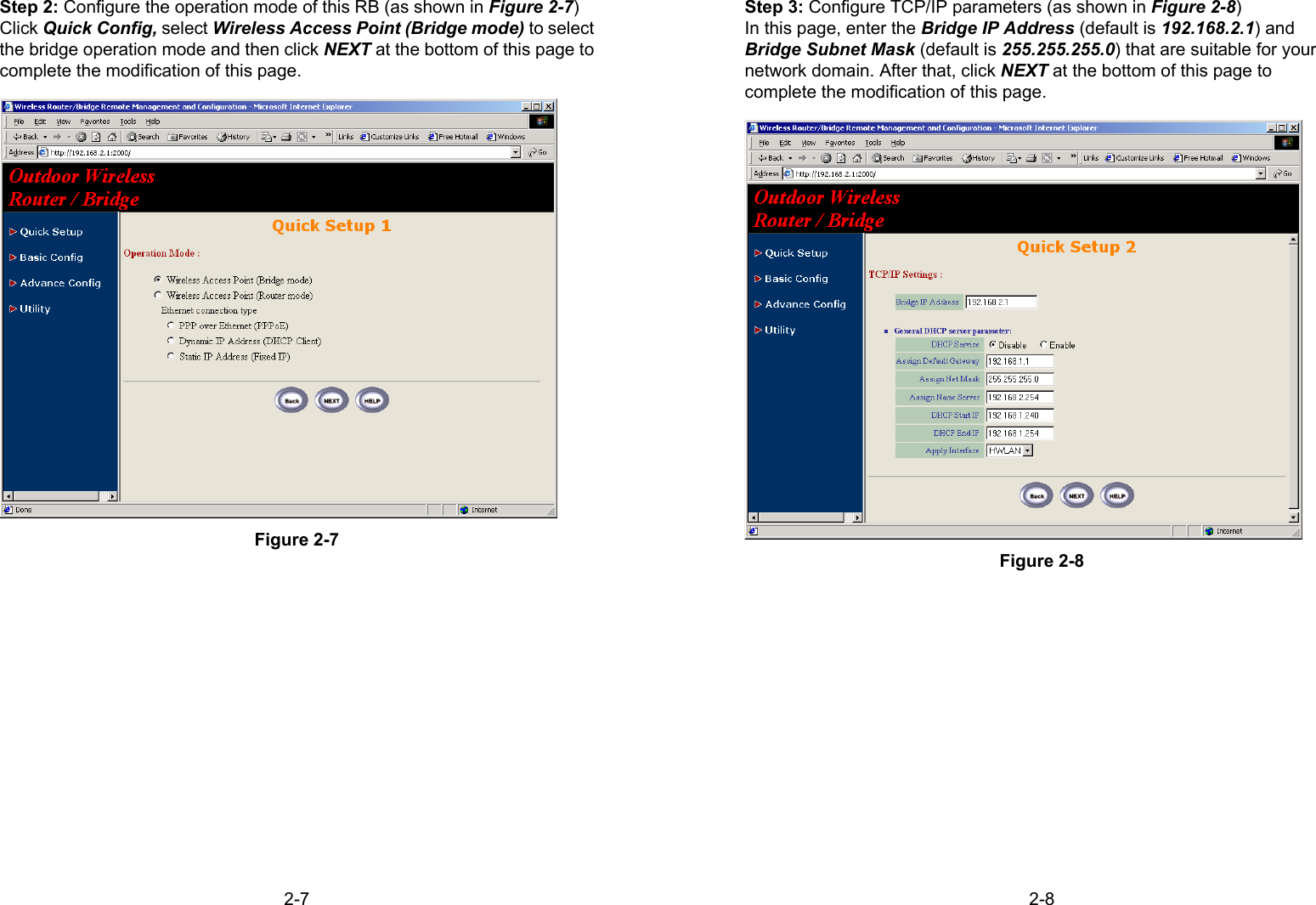
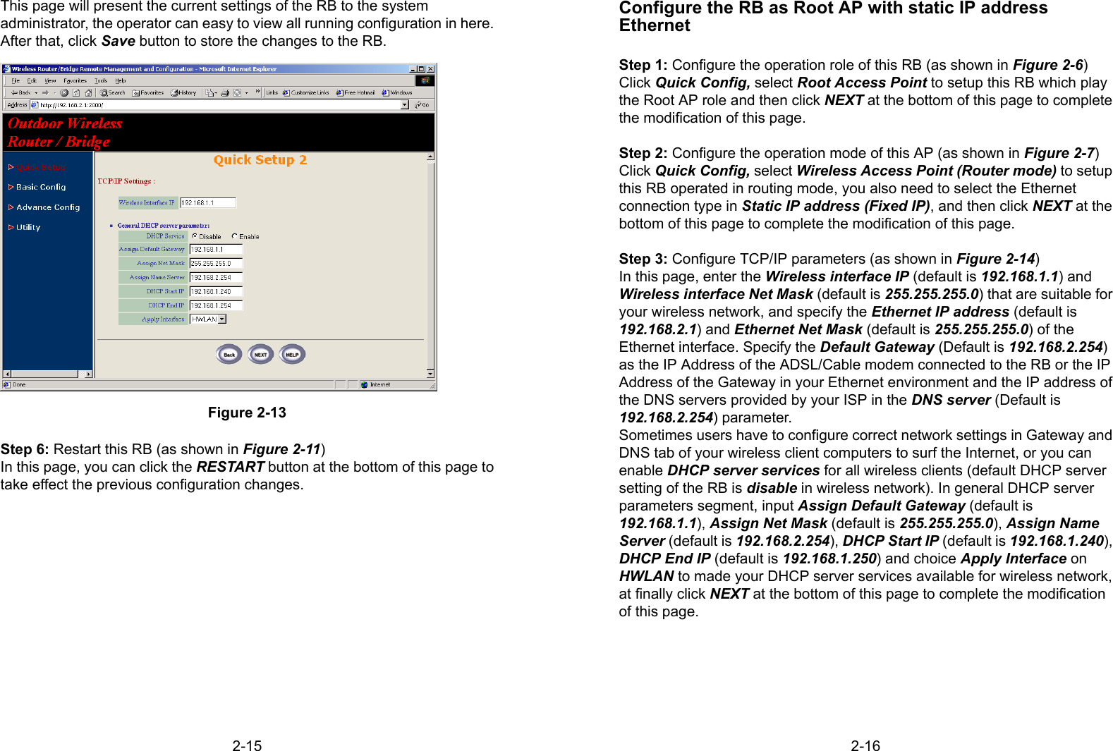
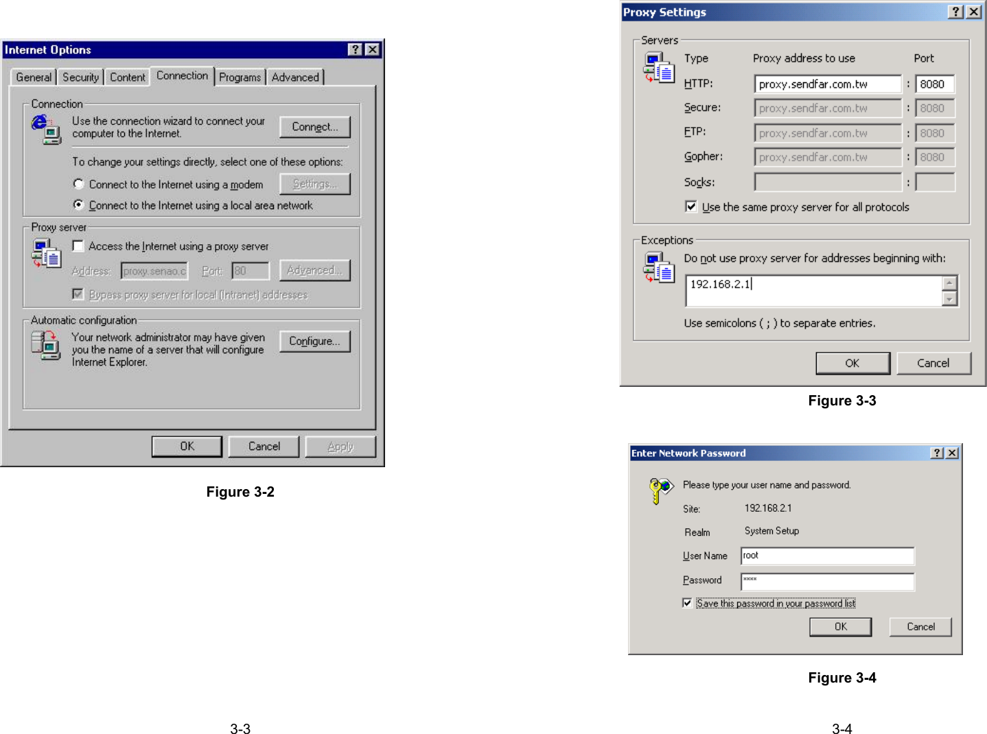
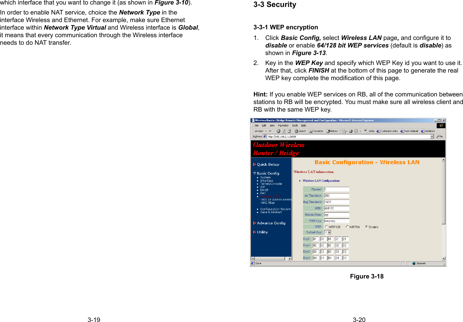
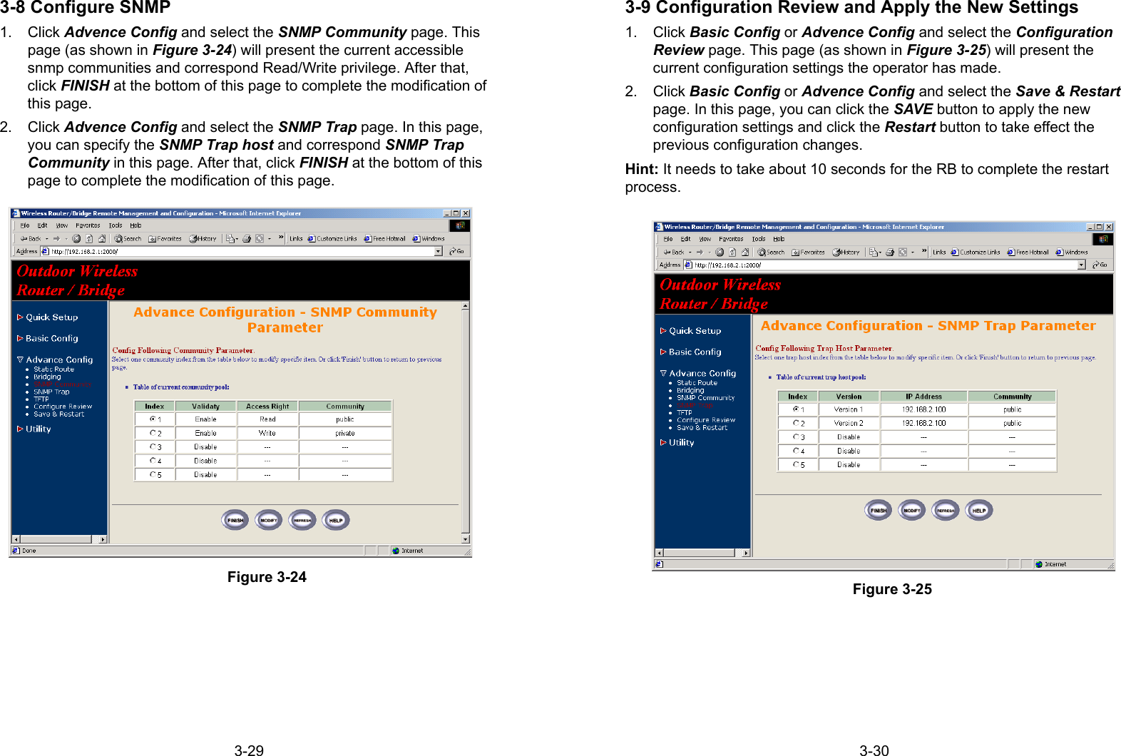
![4-9Figure 4-4*Show: Show the current configuration valuesinterfacePPPip _ sharedhcpsnmpbridgeisprun*reset - defaultwriterebootsusys infoPing <ip> [1~65534| - t] [1~1999]exitconfigurationmax _ user <1~5>telnet_port <1~65534>console _ port <com 1 | com 2 >user _ profileaddattrib <13~30><command | Menu><VT100 | ANSI | LINUX | XTerm>source <-1~10>profile <name> <pass _ conf> <Level 1 | Level 2 | Level 3 | Unlimited>delete (1~5)attrib <13~30><command | Menu><VT100 | ANSI | LINUX | XTerm>source <-1~10>profile <name> <pass _ conf> <Level 1 | Level 2 | Level 3 | Unlimited>legal - addressmodify <1~10> <ip>delete <1~10>modifyattrib <13~30><command | Menu><VT100 | ANSI | LINUX | XTerm>source <-1~10>profile <name> <pass _ conf> <Level 1 | Level 2 | Level 3 | Unlimited>](https://usermanual.wiki/Senao-Co/2511BGPLUS.Manual/User-Guide-267726-Page-37.png)
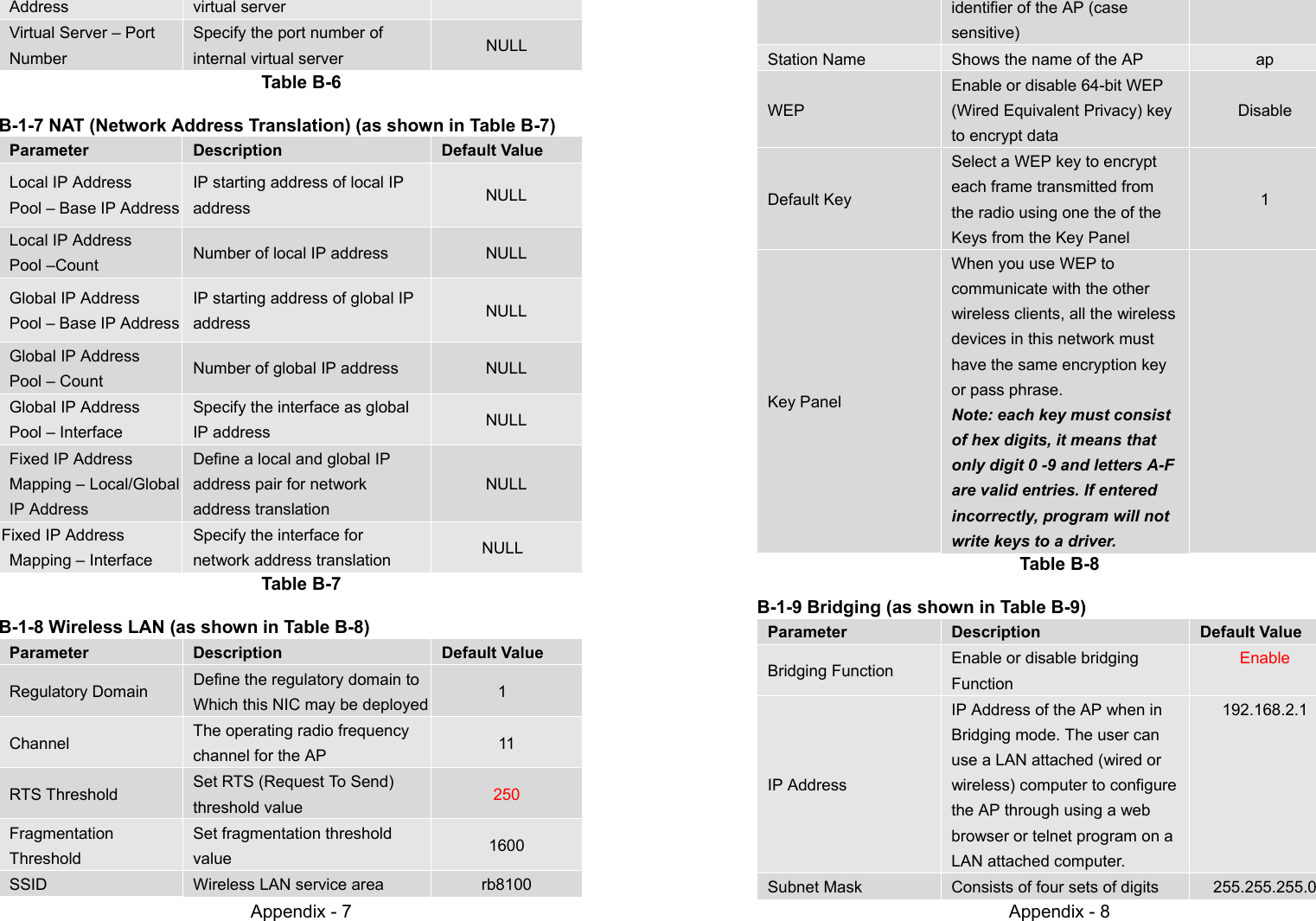
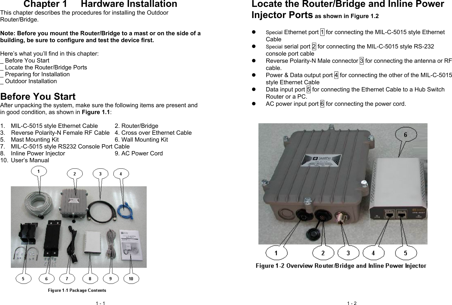
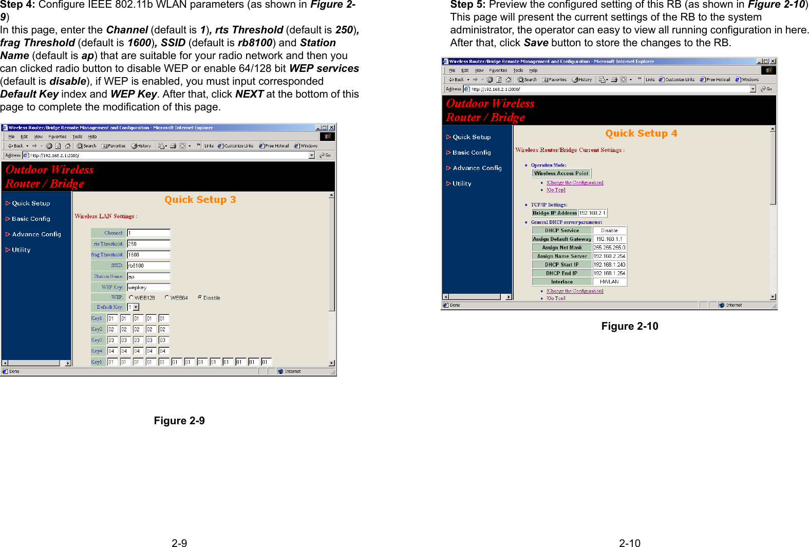
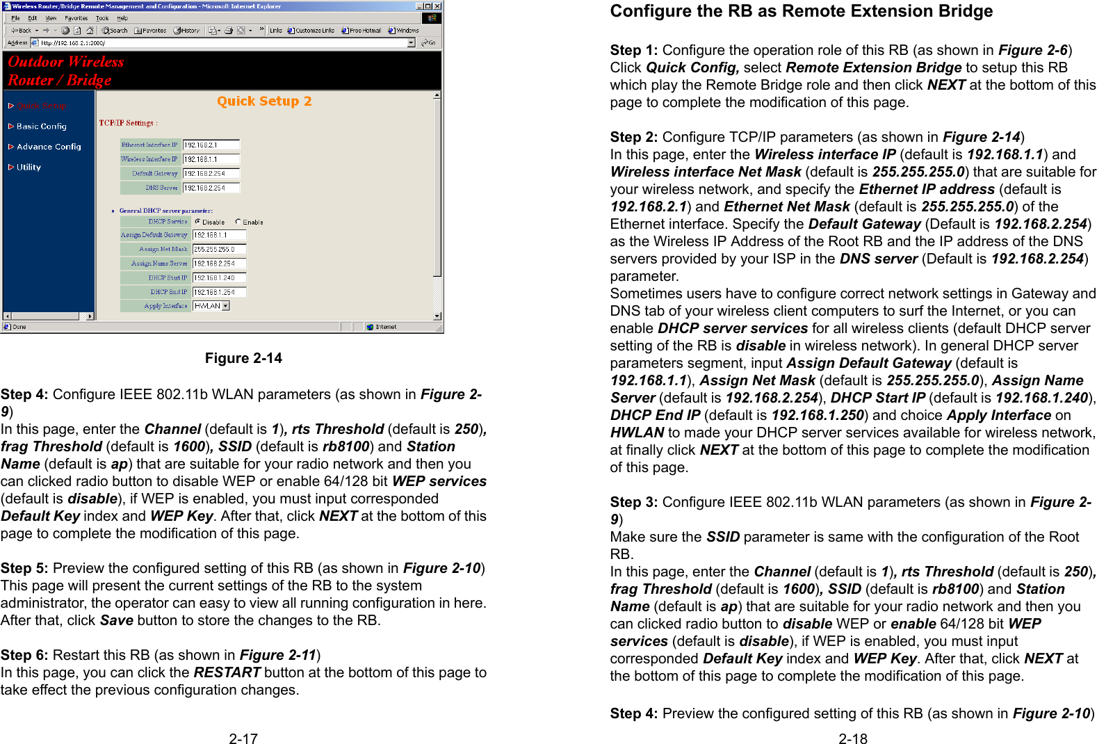
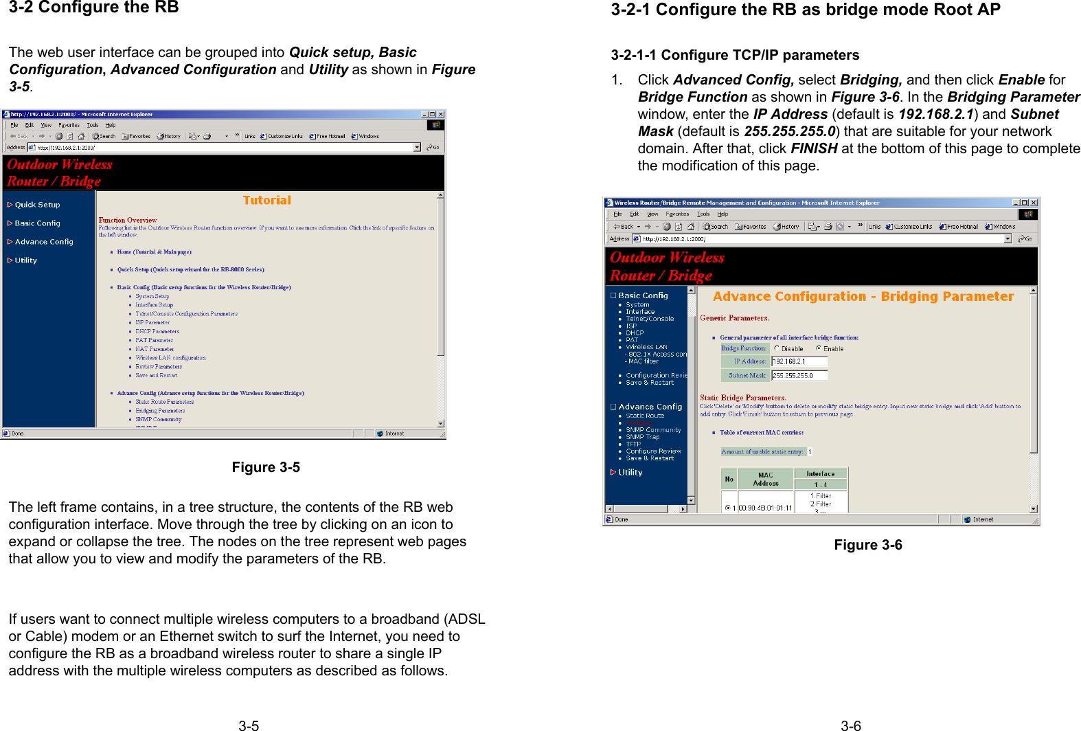
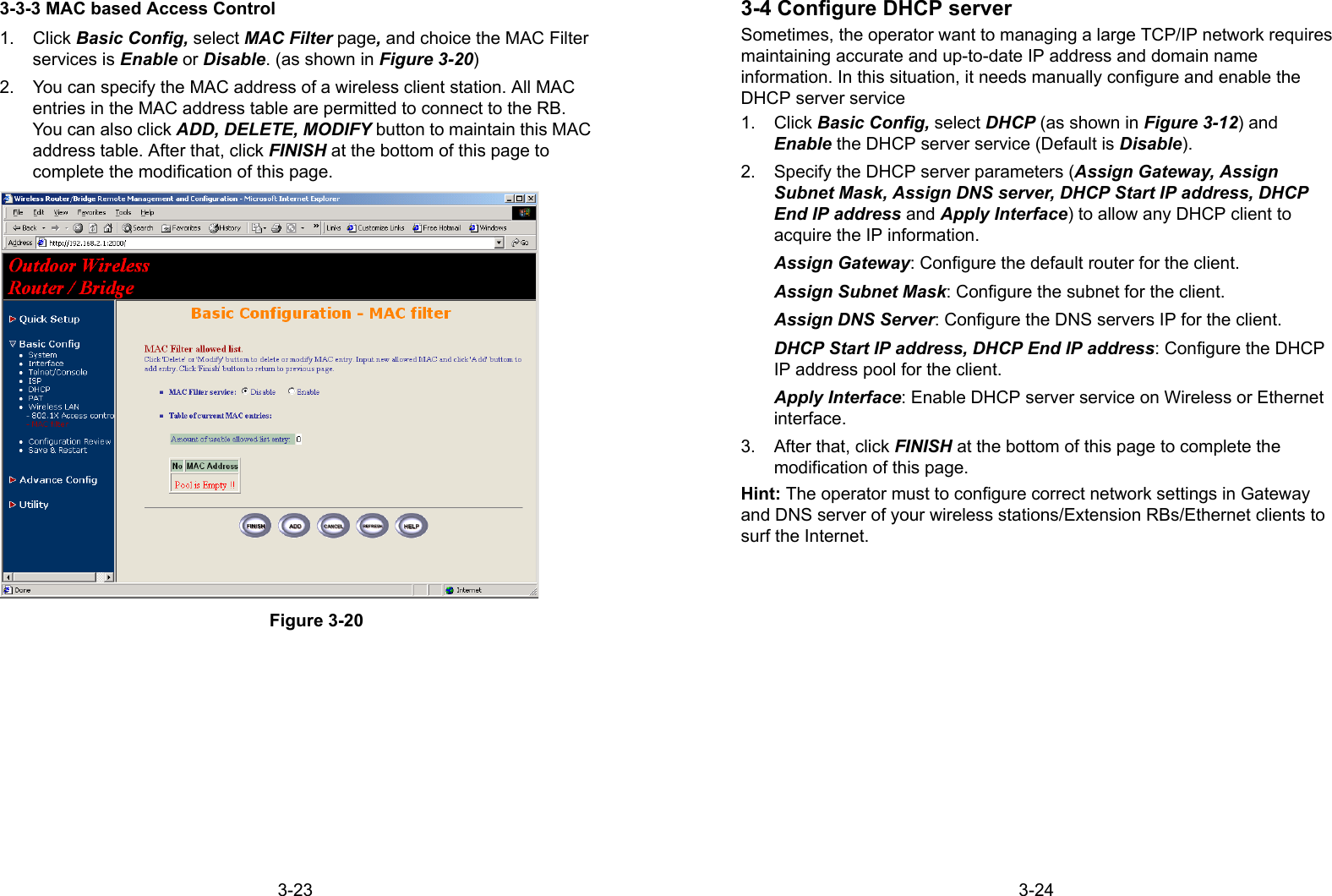
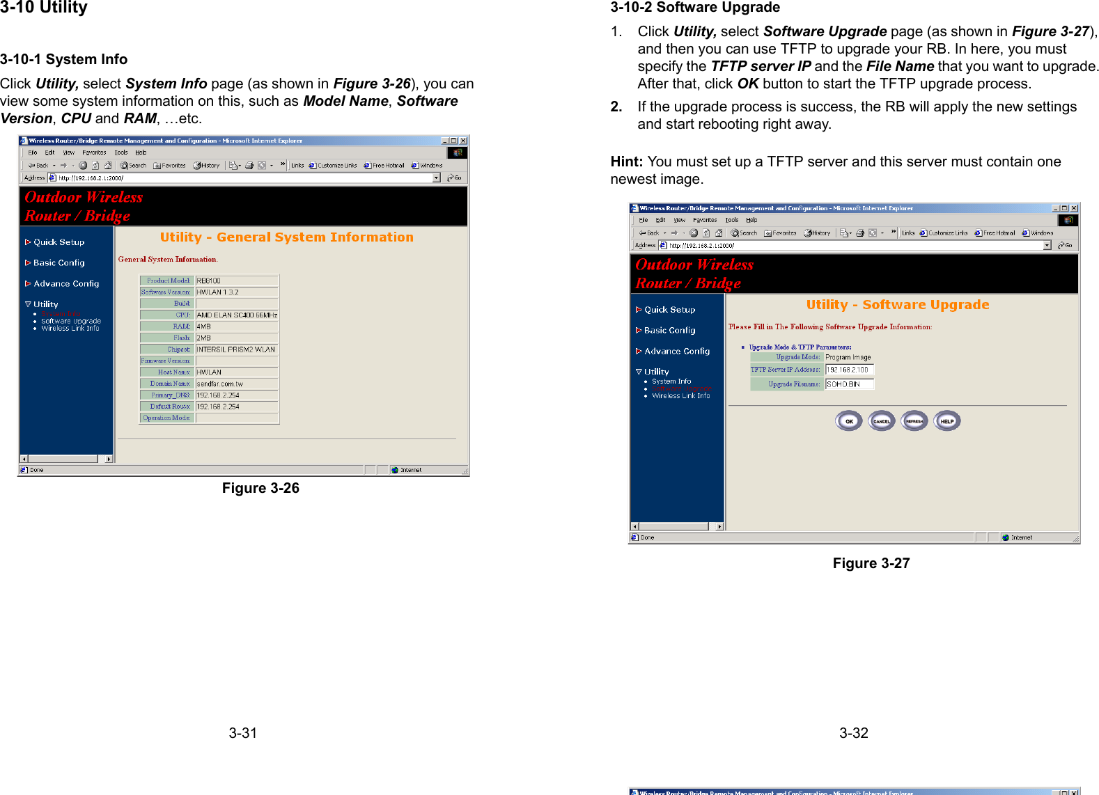
![Appendix - 1Appendix A SpecificationsGeneralCompatibility Fully interoperable with IEEE802.11bcompliant productsRegulation Certifications FCC Part 15, ETSI 300/328Power Supply Output: –48 VDC/0.7A (power overEthernet)Input: 100/240 VAC; 50/60 HzTemperature Range -20 to 70 ℃ (operating) -40 to 80 ℃ (storage)Humidity (non-condensing) 5% to 95% typical Surge Arrester 20KA Surge CurrentRadioFrequency Band 2.4 – 2.484 GHzRadio Type Direct Sequence Spread Spectrum(DSSS)Modulation CCK (11, 5.5Mbps) DQPSK (2Mbps)DBPSK (1Mbps)Operation Channels 11 for North America, 14 for Japan, 13 for Europe, 2 for Spain, 4 for FranceRF Output Power 13dBm(ETS,FR) [ model: RB-8100E],19dBm(FCC) [model: RB-8100]RF Connector Proprietary N-type (Reverse Polarity)Network InformationEthernet Interface 10-Base T (RJ45)IP Sharing Supports NATRoaming Seamless roaming (IEEE802.11bcompliant)Security 64/128-bit WEP data encryptionAppendix - 2ManagementLocal Configuration RS-232 serial portRemote Configuration HTTP, Telnet, SNMPFirmware Upgrade Upgrade via Serial Interface or TFTPIP Auto-configuration Supports DHCP serverPhysical SpecificationsDimensions 245(L) mm x 200(W) mm x 70(H) mmWeight 2100 g](https://usermanual.wiki/Senao-Co/2511BGPLUS.Manual/User-Guide-267726-Page-38.png)