Senao Co 2511BGPLUS Wireless Outdoor Bridge User Manual RBmenu ch0
Senao International Co Ltd Wireless Outdoor Bridge RBmenu ch0
Senao Co >
Contents
- 1. Manual
- 2. Revised Manual 2
Revised Manual 2
SENAO
Wireless Outdoor Bridge
SL-2511BG PLUS
User’s Manual
Before operating the unit, please read this manual thoroughly, and retain it
for future reference.
Contents
Chapter 1 – Hardware Installation
Before You Start .................................................................................... 1-1
Locate the Router/Bridge and Inline Power Injector Ports ………............ 1-2
Preparing Installation ………....................................................….......... 1-3
Outdoor Installation ...........................…………………………………… 1-5
Chapter 2 – Quick Setup
Configure Requirements ........................................................................ 2-1
Configure the RB ......…………………………….................…...….......... 2-4
Configure the RB as bridge mode Root AP .......................…...….......... 2-
5
Configure the RB as Root AP with PPPoE Ethernet connection ........ 2-11
Configure the RB as Root AP with dynamic IP address Ethernet …..... 2-13
Configure the RB as Root AP with static IP address Ethernet ….......... 2-15
Configure the RB as Remote Extension Bridge ....................…...…..... 2-17
Chapter 3 – Further Configuration
Configure Requirements ........................................................................ 3-2
Configure the RB ......…………………………….................…...….......... 3-5
Security ……………………………………........................…...…......…. 3-20
Configure DHCP server …………………........................…...…......…. 3-24
Configure Virtual Server ………………….......................…...…......…. 3-25
Configure Routing Table …………………………….........…...…......…. 3-27
Configure Bridge …………………………........................…...…......…. 3-28
Configure SNMP………………………………………..........…...…......…. 3-29
Configuration Review and Apply the New Settings …………….…..…. 3-30
Utility …………………………………….........……............…...…......…. 3-31
Chapter 4 – Command Line Interface
Appendix A – Specifications
Appendix B – Default Settings
Appendix C – Regulatory Compliance Information
1 - 1
Chapter 1 Hardware Installation
This chapter describes the procedures for installing the Outdoor
Router/Bridge.
Note: Before you mount the Router/Bridge to a mast or on the side of a
building, be sure to configure and test the device first.
Here’s what you’ll find in this chapter:
_ Before You Start
_ Locate the Router/Bridge Ports
_ Preparing for Installation
_ Outdoor Installation
Before You Start
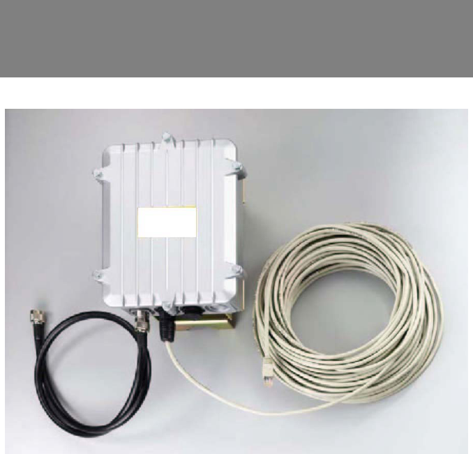
After unpacking the system, make sure the following items are present and
in good condition, as shown in Figure 1.1:
1. MIL-C-5015 style Ethernet Cable 2. Router/Bridge
3. Reverse Polarity-N Female RF Cable 4. Cross over Ethernet Cable
5. Mast Mounting Kit 6. Wall Mounting Kit
7. MIL-C-5015 style RS232 Console Port Cable
8. Inline Power Injector 9. AC Power Cord
10. User’s Manual
1 - 2
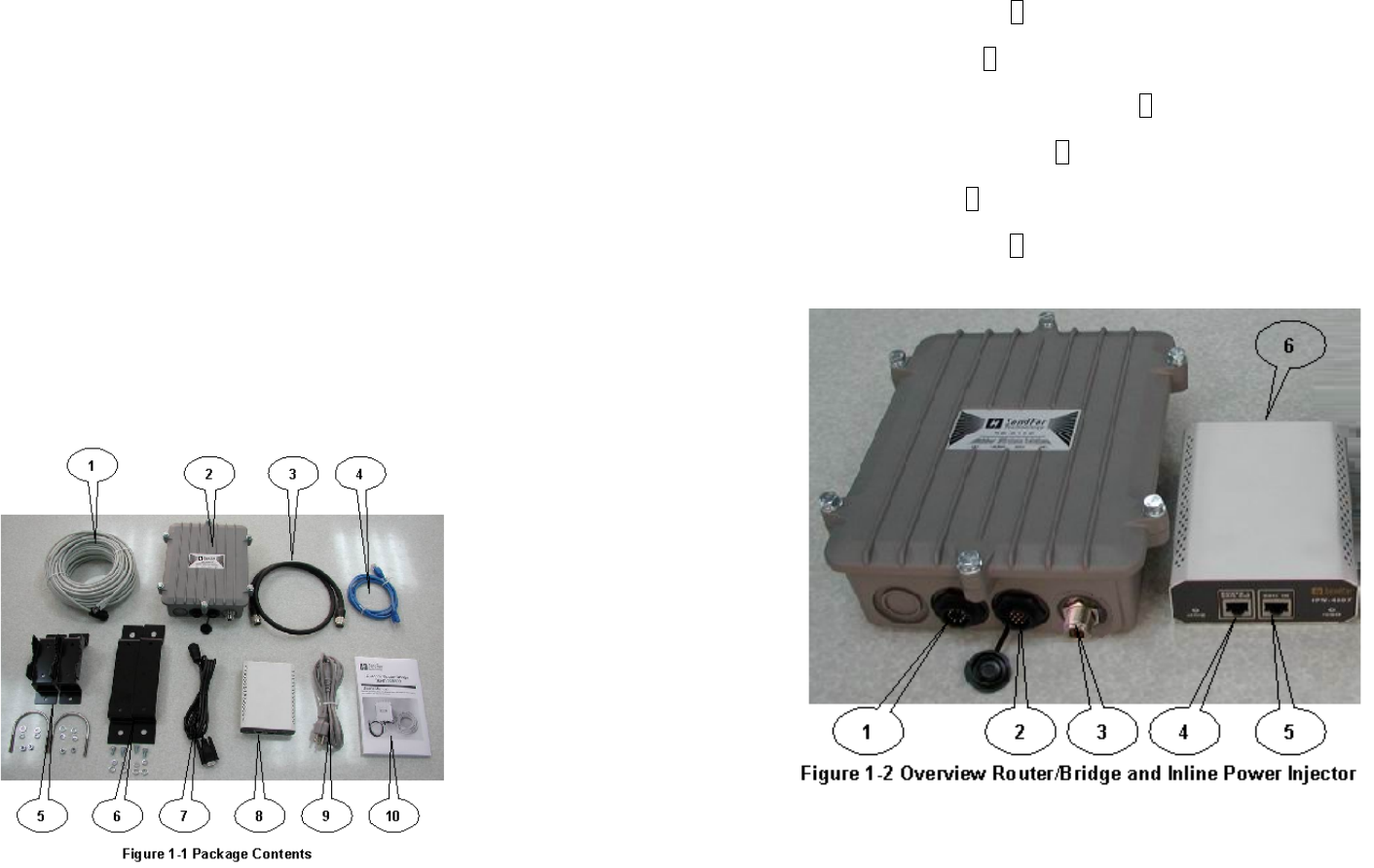
Locate the Router/Bridge and Inline Power
Injector Ports as shown in Figure 1.2
z Special Ethernet port 1 for connecting the MIL-C-5015 style Ethernet
Cable
z Special serial port 2 for connecting the MIL-C-5015 style RS-232
console port cable
z Reverse Polarity-N Male connector 3 for connecting the antenna or RF
cable.
z Power & Data output port 4 for connecting the other of the MIL-C-5015
style Ethernet Cable
z Data input port 5 for connecting the Ethernet Cable to a Hub Switch
Router or a PC.
z AC power input port 6 for connecting the power cord.
1 - 3
Preparing Installation
Before installing your Outdoor Wireless LAN system for your outdoor
application in a hard-to-reach location, we recommend that you configure
and test all the devices first.
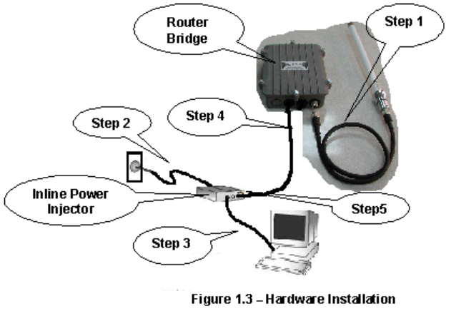
For configuring the Outdoor Router/Bridge, you need follow the quick steps
below to power up your Router/Bridge:
Step 1: With the unit powered off, attach one end of the RF cable to the
antenna connector and then connect the antenna to the other end of the RF
cable as shown in Figure 1.3.
Step 2 Plug the female end of the power cord into the Inline Power Injector,
and then plug the male end of the power cord into a power outlet or power
strip. The Power LED on the front of the Inline Power Injector will light up.
Step 3 Run the cross over Ethernet cable (included in your package) from
Data Input Port (on the front of the Inline Power Injector) to the Ethernet Port
on a PC.
NOTE: This connection is required for setting up initial configuration
1 - 4
information. After configuration is completed, this cable will be removed, and
then you should run an Ethernet cable from Data Input Port (on the front of
the Inline Power Injector) to the LAN connection (such as to a hub, bridge or
directly into a patch panel).
Step 4 Plug the MIL-C-5015 style Ethernet connector into the Special
Ethernet port on the back of the Router/Bridge.
Step 5 Plug the RJ-45 Ethernet connector (the other end of the Special
Ethernet cable) into the Power & Data Output Port on the front of the Inline
Power Injector.
When the Router/Bridge receives power over the Ethernet cable, the
Router/Bridge will start its boot sequence and the Active LED on the front of
the Inline Power Injector will light up.
You can configure the Router/Bridge using the HTML browser, such as
Internet Explorer or Netscape Navigator from a remote host or PC.
(Please consult the “Quick Setup” section).
1 - 5
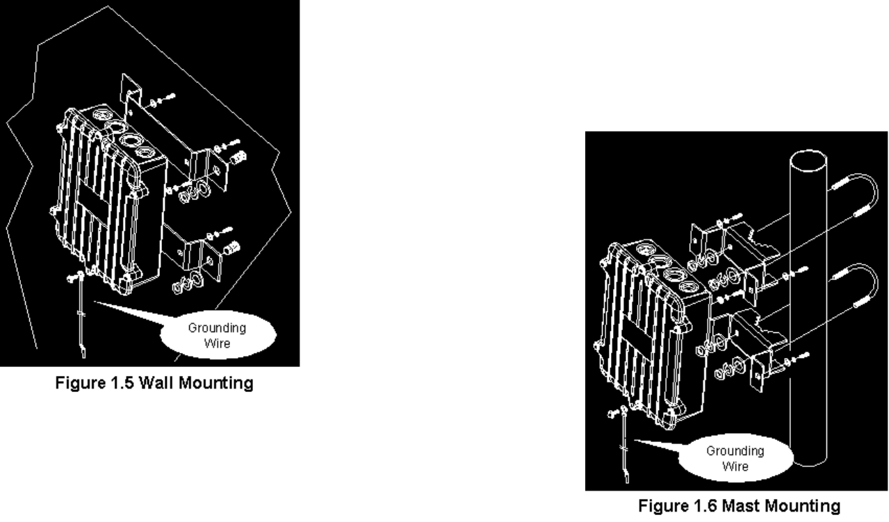
Outdoor Installation
Outdoor Router/Bridge device can be mounted on the side of a
building or mounted to an antenna mast as shown in Figure 1.5 and
Figure 1.6.
A wall (side) mount
allows for mounting an
antenna (mast) on the
side of a building or on
the side of an elevator
penthouse. This will
provide a convenient
mounting location
when the roof
overhang is not
excessive and/or the
location is high
enough to provide a
clear line of sight.
In most situations
mounting an antenna
directly to the wall will
not allow you to
properly align the
antenna with the
corresponding antenna
at the opposite end of
your wireless link. As
poor alignment will
typically result in poor performance, we advise you to always mount
the Outdoor Router/Bridge and antenna to a mast.
Antenna Mast Requirements
To accommodate the outdoor antennas, the antenna mast must satisfy
the following requirements:
a. The construction of the mast must be of a sturdy, weatherproof and
no corrosive material like for example galvanized or stainless steel
construction pipe.
1 - 6
b. Typical diameter of the mast should be between 35 mm (1.4 in.) and
41 mm (1.625 in.). Subject to the type of antenna that you intend to
install other diameters may be possible as well.
c. The height of the antenna mast must be sufficient to allow the
antenna to be installed at least 1.5 m (5 ft.) above the peak of roof. If the
roof is metal, then the height of the antenna should be a minimum of 3
m (10 ft) above the roof.
d. The mast or wall-bracket must be free from any substance that may
prevent
a good electrical connection with the antenna; for example, paint.
Grounding
A safety grounding
system is necessary to
protect your outdoor
installation from
lightning strikes and
the build-up of static
electricity.
So direct grounding of
the antenna mast,
Outdoor Router/Bridge
and
Surge Arrester is very
important. The
Outdoor Router/Bridge
has built in Surge
Arrester. So Mounting
the Outdoor
Router/Bridge on the
antenna mast, you
have to connect the
Outdoor Router/Bridge
to the same grounding
system with the AC
wall outlet.
The grounding system must comply with the National Electrical Code
and safety standards that apply in your country. Always check with a
1 - 7
qualified electrician if you are in doubt as to whether your outdoor
installation is properly grounded.
Antenna Alignment
For optimal performance of your wireless link, make sure that the
antennas are properly aligned (facing one another “eye-to-eye”). To
align the antennas:
_ Use a pair of binoculars and/or a map of the area and compass to
point the antennas to one another.
_ Use the Utility- “Wireless Link Info” in the Web Configure as
described in the "Utility " section to analyze the radio link quality.
The “Wireless Link Info” will enable you to display the levels of signal
strength and link quality.
Looking at the Wireless Link Info screen, you can interactively
optimize antenna alignment if required, by making small modifications
in the antenna orientation.
_ Alternatively, consult a professional Antenna Installation Service to
optimize the antenna alignment.
Omni-directional antennas are characterized by a wide radiation
pattern. Therefore alignment of this type of antennas is less critical
than for directional antennas.
2-1
Chapter 2 Quick Setup
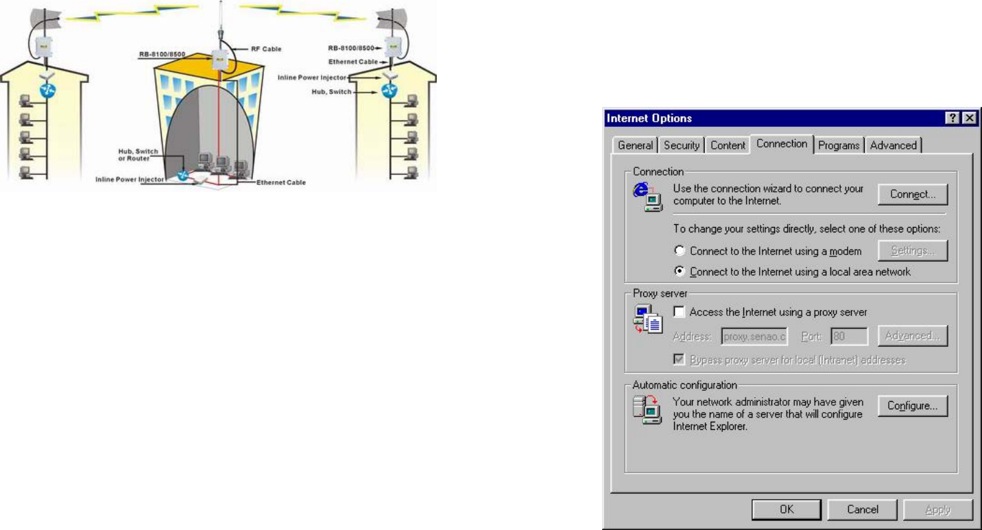
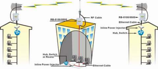
This chapter describes how to easy setup and configure the Outdoor
Wireless Router/Bridge System (RB). The RB can be configured into two
roles: Root Access Point (Root AP) and Remote Extension Bridge (Remote
RB) to accomplish the broadband wireless point-to-point and multipoint
systems (as shown in Figure 2-1.). Users can use a LAN-attached (wired or
wireless) computer to configure the RB through a web browser or a telnet
session on a LAN computer.
Figure 2-1
In this chapter, we only describe how to quickly configure the RB with a web
browser. For detailed descriptions of the many configuration parameters and
network configuration, refer to Chapter 3.
Configure Requirements
Before setup, we must install RB first
1. Connect power adaptor and power on the RB
2. Connect the Ethernet cable for connecting the RB to the network
2-2
3. Connect a computer to the same network with this RB
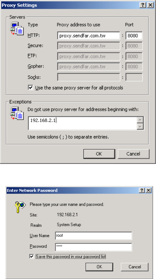
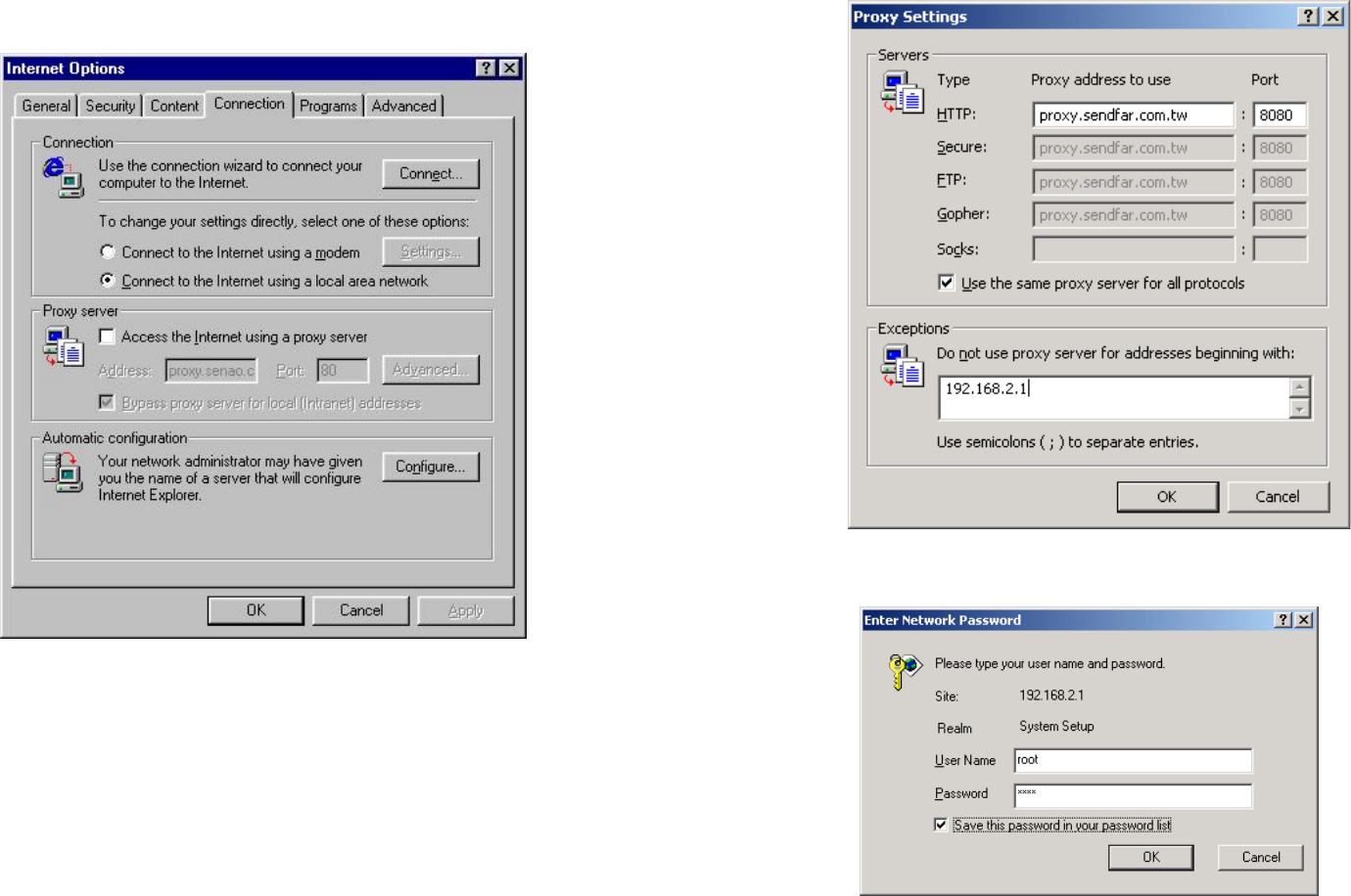
4. Start your Microsoft Internet Explorer web browser program from a
LAN-attached computer. To access the web interface of the RB, you
have to disable Access the Internet using a proxy server function in
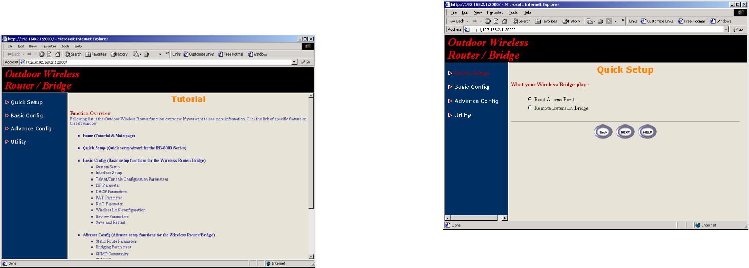
View / Internet Options / Connection as shown in Figure 2-2 or add
the IP address of the AP (default IP address is 192.168.2.1) to Bypass
proxy server for local addresses as shown in Figure 2-3.
5. Type the IP address and HTTP port of the RB (default IP address is
192.168.2.1) in the address field (http://192.168.2.1:2000/) and press
Enter. Make sure that the IP addresses of RB and your computer are in
the same subnet.
6. After the connection is established, you will see the User Identification
Window as shown in Figure 2-4 Enter the proper User Name and
Password to see the web user interface of the RB. The default user
name and password is root and root, respectively.
2-3
Figure 2-2
Figure 2-3
2-4
Figure 2-4
2-5
Configure the RB
The RB can be configured into two operation roles:
Root Access Point ( Root AP ) and Remote Extension Bridge ( Remote RB ),
the Root AP can performed in four operation modes
1. Wireless Access bridge
2. Wireless Access router with PPPoE Ethernet connection
3. Wireless Access router with dynamic IP address Ethernet
4. Wireless Access router with static IP address Ethernet
The RB is shipped with default configuration is as a bridge between an
Ethernet and wireless network. Users simply need to attach the RB to your
wired LAN. If users would like to configure the RB, please refer to the
following procedures.
The web user interface can be grouped into Quick setup, Basic
Configuration, Advanced Configuration and Utility as shown in Figure
2-5.
Figure 2-5
2-6
The left frame contains, in a tree structure, the contents of the RB web
configuration interface. Move through the tree by clicking on an icon to
expand or collapse the tree. The nodes on the tree represent web pages
that allow you to view and modify the parameters of the RB. In here, you can
click the Quick setup and following the setup wizard flow to configure this
RB step by step.
Configure the RB as bridge mode Root AP
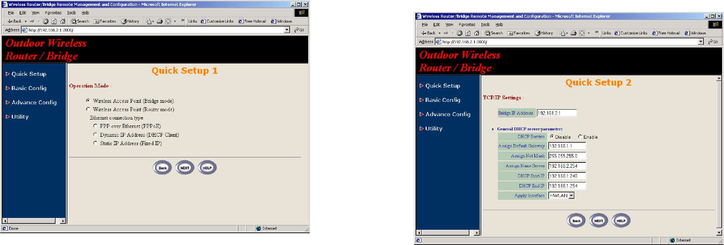
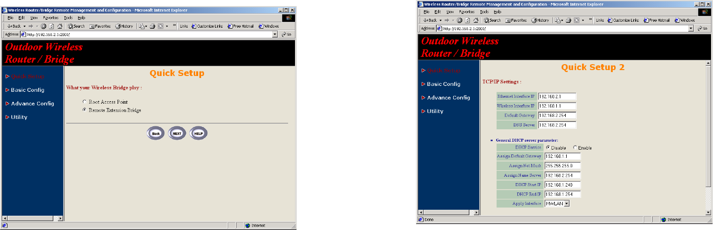
Step 1: Configure the operation role of this RB (as shown in Figure 2-6)
Click Quick Config, select Root Access Point to setup this RB which play
the Root AP role and then click NEXT at the bottom of this page to complete
the modification of this page.
Figure 2-6
2-7
Step 2: Configure the operation mode of this RB (as shown in Figure 2-7)
Click Quick Config, select Wireless Access Point (Bridge mode) to select
the bridge operation mode and then click NEXT at the bottom of this page to
complete the modification of this page.
Figure 2-7
2-8
Step 3: Configure TCP/IP parameters (as shown in Figure 2-8)
In this page, enter the Bridge IP Address (default is 192.168.2.1) and
Bridge Subnet Mask (default is 255.255.255.0) that are suitable for your
network domain. After that, click NEXT at the bottom of this page to
complete the modification of this page.
Figure 2-8
2-9
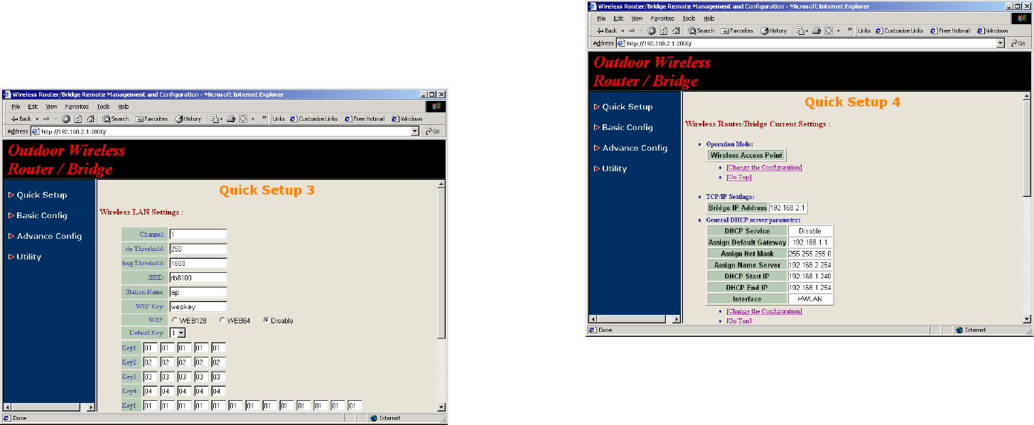
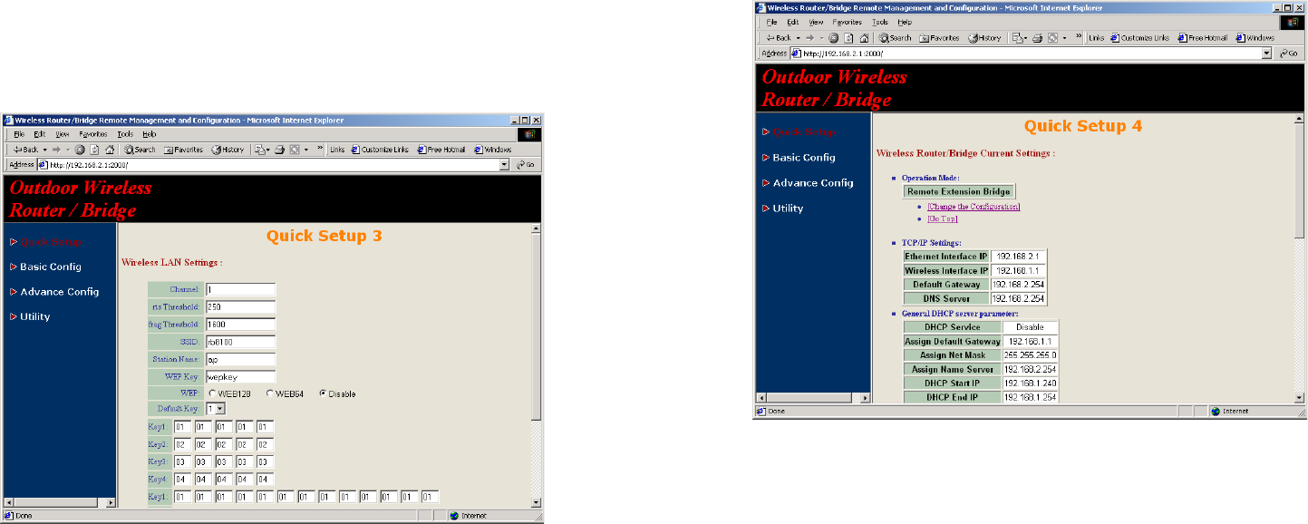
Step 4: Configure IEEE 802.11b WLAN parameters (as shown in Figure 2-
9)
In this page, enter the Channel (default is 1), rts Threshold (default is 250),
frag Threshold (default is 1600), SSID (default is rb8100) and Station
Name (default is ap) that are suitable for your radio network and then you
can clicked radio button to disable WEP or enable 64/128 bit WEP services
(default is disable), if WEP is enabled, you must input corresponded
Default Key index and WEP Key. After that, click NEXT at the bottom of this
page to complete the modification of this page.
Figure 2-9
2-10
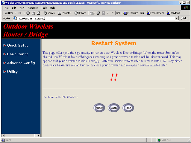
Step 5: Preview the configured setting of this RB (as shown in Figure 2-10)
This page will present the current settings of the RB to the system
administrator, the operator can easy to view all running configuration in here.
After that, click Save button to store the changes to the RB.
Figure 2-10
2-11
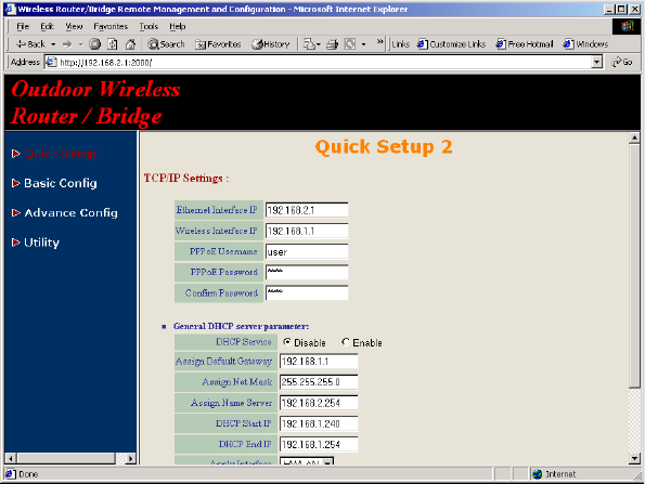
Step 6: Restart this RB (as shown in Figure 2-11)
In this page, you can click the RESTART button at the bottom of this page to
take effect the previous configuration changes.
Figure 2-11
2-12
Configure the RB as Root AP with PPPoE Ethernet
connection
Step 1: Configure the operation role of this RB (as shown in Figure 2-6)
Click Quick Config, select Root Access Point to setup this RB which play
the Root AP role and then click NEXT at the bottom of this page to complete
the modification of this page.
Step 2: Configure the operation mode of this RB (as shown in Figure 2-7)
Click Quick Config, select Wireless Access Point (Router mode) to setup
this RB operated in routing mode, you also need to select the Ethernet
connection type in PPP over Ethernet (PPPoE), and then click NEXT at the
bottom of this page to complete the modification of this page.
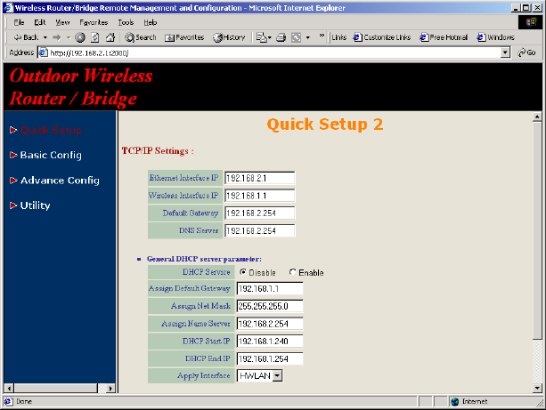
Step 3: Configure TCP/IP parameters (as shown in Figure 2-12)
In this page, enter the Wireless interface IP (default is 192.168.1.1) and
Wireless interface Net Mask (default is 255.255.255.0) that are suitable for
your wireless network, and specify the Ethernet IP address (default is
192.168.2.1) and Ethernet Net Mask (default is 255.255.255.0) of the
Ethernet interface. And then, if you are an ADSL subscriber, you may
specify that your personal ISP provided PPPoE Username and PPPoE
Password to enable ADSL broadband access.
Sometimes users have to conFigure 2-correct network settings in Gateway
and DNS tab of your wireless client computers to surf the Internet, or you
can enable DHCP server services for all wireless clients (default DHCP
server setting of the RB is disable in wireless network). In general DHCP
server parameters segment, input Assign Default Gateway (default is
192.168.2.254), Assign Net Mask (default is 255.255.255.0), Assign Name
Server (default is 192.168.1.1), DHCP Start IP (default is 192.168.1.240),
DHCP End IP (default is 192.168.1.250) and choice Apply Interface on
HWLAN to made your DHCP server services available for wireless network,
at finally click NEXT at the bottom of this page to complete the modification
of this page.
2-13
Figure 2-12
Step 4: Configure IEEE 802.11b WLAN parameters (as shown in Figure 2-
9)
In this page, enter the Channel (default is 1), rts Threshold (default is 250),
frag Threshold (default is 1600), SSID (default is rb8100) and Station
Name (default is ap) that are suitable for your radio network and then you
can clicked radio button to disable WEP or enable 64/128 bit WEP services
(default is disable), if WEP is enabled, you must input corresponded
Default Key index and WEP Key. After that, click NEXT at the bottom of this
page to complete the modification of this page.
Step 5: Preview the configured setting of this RB (as shown in Figure 2-10)
This page will present the current settings of the RB to the system
administrator, the operator can easy to view all running configuration in here.
After that, click Save button to store the changes to the RB.
Step 6: Restart this RB (as shown in Figure 2-11)
In this page, you can click the RESTART button at the bottom of this page to
take effect the previous configuration changes.
2-14
Configure the RB as Root AP with dynamic IP address
Ethernet
Step 1: Configure the operation role of this RB (as shown in Figure 2-6)
Click Quick Config, select Root Access Point to setup this RB which play
the Root AP role and then click NEXT at the bottom of this page to complete
the modification of this page.
Step 2: Configure the operation mode of this RB (as shown in Figure 2-7)
Click Quick Config, select Wireless Access Point (Router mode) to setup
this RB operated in routing mode, you also need to select the Ethernet
connection type in Dynamic IP address (DHCP Client), and then click
NEXT at the bottom of this page to complete the modification of this page.
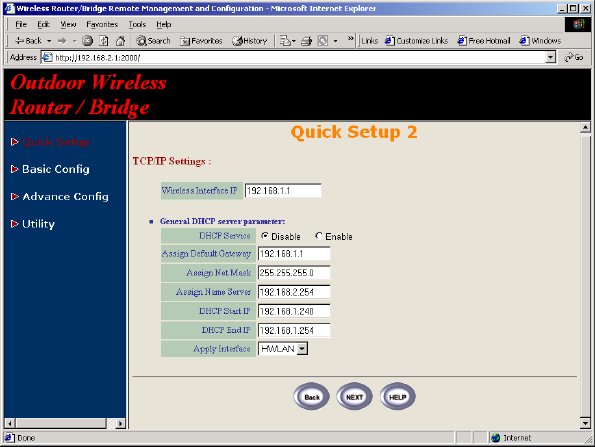
Step 3: Configure TCP/IP parameters (as shown in Figure 2-13)
In this page, enter the Wireless interface IP (default is 192.168.1.1) and
Wireless interface Net Mask (default is 255.255.255.0) that are suitable for
your wireless network.
Sometimes users have to configure correct network settings in Gateway and
DNS tab of your wireless client computers to surf the Internet, or you can
enable DHCP server services for all wireless clients (default DHCP server
setting of the RB is disable in wireless network). In general DHCP server
parameters segment, input Assign Default Gateway (default is
192.168.1.1), Assign Net Mask (default is 255.255.255.0), Assign Name
Server (default is 192.168.2.254), DHCP Start IP (default is 192.168.1.240),
DHCP End IP (default is 192.168.1.250) and choice Apply Interface on
HWLAN to made your DHCP server services available for wireless network,
at finally click NEXT at the bottom of this page to complete the modification
of this page.
Step 4: Configure IEEE 802.11b WLAN parameters (as shown in Figure 2-
9)
In this page, enter the Channel (default is 1), rts Threshold (default is 250),
frag Threshold (default is 1600), SSID (default is rb8100) and Station
Name (default is ap) that are suitable for your radio network and then you
can clicked radio button to disable WEP or enable 64/128 bit WEP services
(default is disable), if WEP is enabled, you must input corresponded
Default Key index and WEP Key. After that, click NEXT at the bottom of this
page to complete the modification of this page.
Step 5: Preview the configured setting of this RB (as shown in Figure 2-10)
2-15
This page will present the current settings of the RB to the system
administrator, the operator can easy to view all running configuration in here.
After that, click Save button to store the changes to the RB.
Figure 2-13
Step 6: Restart this RB (as shown in Figure 2-11)
In this page, you can click the RESTART button at the bottom of this page to
take effect the previous configuration changes.
2-16
Configure the RB as Root AP with static IP address
Ethernet
Step 1: Configure the operation role of this RB (as shown in Figure 2-6)
Click Quick Config, select Root Access Point to setup this RB which play
the Root AP role and then click NEXT at the bottom of this page to complete
the modification of this page.
Step 2: Configure the operation mode of this AP (as shown in Figure 2-7)
Click Quick Config, select Wireless Access Point (Router mode) to setup
this RB operated in routing mode, you also need to select the Ethernet
connection type in Static IP address (Fixed IP), and then click NEXT at the
bottom of this page to complete the modification of this page.
Step 3: Configure TCP/IP parameters (as shown in Figure 2-14)
In this page, enter the Wireless interface IP (default is 192.168.1.1) and
Wireless interface Net Mask (default is 255.255.255.0) that are suitable for
your wireless network, and specify the Ethernet IP address (default is
192.168.2.1) and Ethernet Net Mask (default is 255.255.255.0) of the
Ethernet interface. Specify the Default Gateway (Default is 192.168.2.254)
as the IP Address of the ADSL/Cable modem connected to the RB or the IP
Address of the Gateway in your Ethernet environment and the IP address of
the DNS servers provided by your ISP in the DNS server (Default is
192.168.2.254) parameter.
Sometimes users have to configure correct network settings in Gateway and
DNS tab of your wireless client computers to surf the Internet, or you can
enable DHCP server services for all wireless clients (default DHCP server
setting of the RB is disable in wireless network). In general DHCP server
parameters segment, input Assign Default Gateway (default is
192.168.1.1), Assign Net Mask (default is 255.255.255.0), Assign Name
Server (default is 192.168.2.254), DHCP Start IP (default is 192.168.1.240),
DHCP End IP (default is 192.168.1.250) and choice Apply Interface on
HWLAN to made your DHCP server services available for wireless network,
at finally click NEXT at the bottom of this page to complete the modification
of this page.
2-17
Figure 2-14
Step 4: Configure IEEE 802.11b WLAN parameters (as shown in Figure 2-
9)
In this page, enter the Channel (default is 1), rts Threshold (default is 250),
frag Threshold (default is 1600), SSID (default is rb8100) and Station
Name (default is ap) that are suitable for your radio network and then you
can clicked radio button to disable WEP or enable 64/128 bit WEP services
(default is disable), if WEP is enabled, you must input corresponded
Default Key index and WEP Key. After that, click NEXT at the bottom of this
page to complete the modification of this page.
Step 5: Preview the configured setting of this RB (as shown in Figure 2-10)
This page will present the current settings of the RB to the system
administrator, the operator can easy to view all running configuration in here.
After that, click Save button to store the changes to the RB.
Step 6: Restart this RB (as shown in Figure 2-11)
In this page, you can click the RESTART button at the bottom of this page to
take effect the previous configuration changes.
2-18
Configure the RB as Remote Extension Bridge
Step 1: Configure the operation role of this RB (as shown in Figure 2-6)
Click Quick Config, select Remote Extension Bridge to setup this RB
which play the Remote Bridge role and then click NEXT at the bottom of this
page to complete the modification of this page.
Step 2: Configure TCP/IP parameters (as shown in Figure 2-14)
In this page, enter the Wireless interface IP (default is 192.168.1.1) and
Wireless interface Net Mask (default is 255.255.255.0) that are suitable for
your wireless network, and specify the Ethernet IP address (default is
192.168.2.1) and Ethernet Net Mask (default is 255.255.255.0) of the
Ethernet interface. Specify the Default Gateway (Default is 192.168.2.254)
as the Wireless IP Address of the Root RB and the IP address of the DNS
servers provided by your ISP in the DNS server (Default is 192.168.2.254)
parameter.
Sometimes users have to configure correct network settings in Gateway and
DNS tab of your wireless client computers to surf the Internet, or you can
enable DHCP server services for all wireless clients (default DHCP server
setting of the RB is disable in wireless network). In general DHCP server
parameters segment, input Assign Default Gateway (default is
192.168.1.1), Assign Net Mask (default is 255.255.255.0), Assign Name
Server (default is 192.168.2.254), DHCP Start IP (default is 192.168.1.240),
DHCP End IP (default is 192.168.1.250) and choice Apply Interface on
HWLAN to made your DHCP server services available for wireless network,
at finally click NEXT at the bottom of this page to complete the modification
of this page.
Step 3: Configure IEEE 802.11b WLAN parameters (as shown in Figure 2-
9)
Make sure the SSID parameter is same with the configuration of the Root
RB.
In this page, enter the Channel (default is 1), rts Threshold (default is 250),
frag Threshold (default is 1600), SSID (default is rb8100) and Station
Name (default is ap) that are suitable for your radio network and then you
can clicked radio button to disable WEP or enable 64/128 bit WEP
services (default is disable), if WEP is enabled, you must input
corresponded Default Key index and WEP Key. After that, click NEXT at
the bottom of this page to complete the modification of this page.
Step 4: Preview the configured setting of this RB (as shown in Figure 2-10)

2-19
This page will present the current settings of the RB to the system
administrator, the operator can easy to view all running configuration in here.
After that, click Save button to store the changes to the RB.
Step 5: Restart this RB (as shown in Figure 2-11)
In this page, you can click the RESTART button at the bottom of this page to
take effect the previous configuration changes.
Hint: Users may to configure correct network settings as following sample
Remote
Extension
Bridge 1
R
oot
AP
Remote
Extension
Bridge 2
Wireless linkWireless link
Wireless IP: 192.168.1.1
SSID : rb8100
Channel : 1
Ethernet IP: 192.168.2.1
Default Route: 192.168.2.254
Static Route:
192.168.10.0 / 24 / 192.168.1.2
192.168.20.0 / 24 / 192.168.1.3
Wireless IP: 192.168.1.3
SSID : rb8100
Channel : 1
Station Name: ext2
Ethernet IP: 192.168.20.1
Default Route: 192.168.1.1
Wireless IP: 192.168.1.2
SSID : rb8100
Channel : 1
Station Name: ext1
Ethernet IP: 192.168.10.1
Default Route: 192.168.1.1
3-1
Chapter 3 Further Configuration
In this chapter, we give more detailed descriptions of the network
configuration and utilities usage.
The RB can be setup as the Root Access Point (Root AP) or Remote
Extension Bridge (Remote RB).
z Root Access Point (Root AP): it can performed in four operation
modes:
1. Wireless Access bridge
2. Wireless Access router with PPPoE Ethernet connection
3. Wireless Access router with dynamic IP address Ethernet
4. Wireless Access router with static IP address Ethernet
z Remote Extension Bridge (Remote RB),
To create an Outdoor Point-to-Multipoint network (as shown in Figure 3-1),
select a centrally located station that is able to send and receive from every
other station in the network. This station is your “Root AP”. Each of the other
stations is setup as “Remote RB”.
Figure 3-1
3-2
3-1 Configure Requirements
The RB is shipped with configuration that can be utilized right out of the box.
Default configuration is as a bridge between an Ethernet and wireless
network. Users simply need to attach the RB to your wired LAN. Default
wireless SSID is rb8100, respectively. If users would like to configure the RB,
please refer to the following procedures.
1. Start your Microsoft Internet Explorer web browser program from a
LAN-attached computer. To access the web interface of the RB, you
have to disable Access the Internet using a proxy server function in
View / Internet Options / Connection as shown in Figure 3-2 or add
the IP address of the RB (default IP address is 192.168.2.1) to Bypass
proxy server for local addresses as shown in Figure 3-3.
2. Type the IP address and HTTP port of the RB (default IP address is
192.168.2.1) in the address field (http://192.168.2.1:2000/) and press
Enter. Make sure that the IP addresses of RB and your computer are in
the same subnet.
3. After the connection is established, you will see the User Identification
Window as shown in Figure3- 4 Enter the proper User Name and
Password to see the web user interface of the RB. The default user
name and password is root and root, respectively.
3-3
Figure 3-2
3-4
Figure 3-3
Figure 3-4
3-5
3-2 Configure the RB
The web user interface can be grouped into Quick setup, Basic
Configuration, Advanced Configuration and Utility as shown in Figure
3-5.
Figure 3-5
The left frame contains, in a tree structure, the contents of the RB web
configuration interface. Move through the tree by clicking on an icon to
expand or collapse the tree. The nodes on the tree represent web pages
that allow you to view and modify the parameters of the RB.
If users want to connect multiple wireless computers to a broadband (ADSL
or Cable) modem or an Ethernet switch to surf the Internet, you need to
configure the RB as a broadband wireless router to share a single IP
address with the multiple wireless computers as described as follows.
3-6
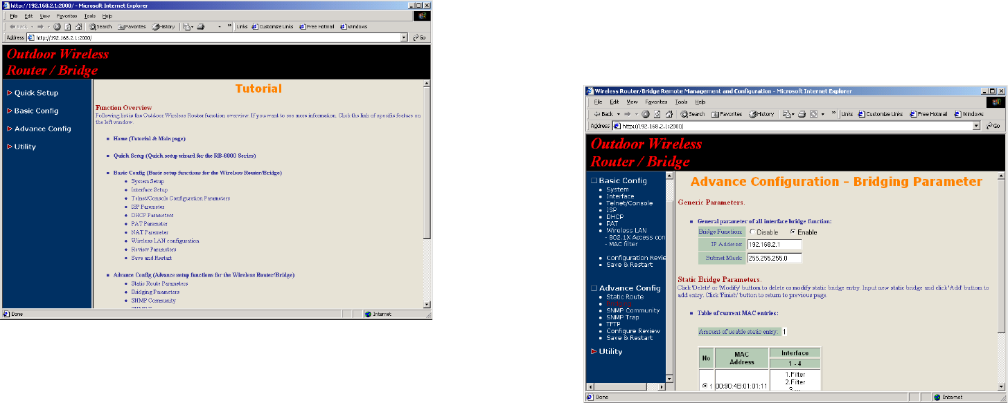
3-2-1 Configure the RB as bridge mode Root AP
3-2-1-1 Configure TCP/IP parameters
1. Click Advanced Config, select Bridging, and then click Enable for
Bridge Function as shown in Figure 3-6. In the Bridging Parameter
window, enter the IP Address (default is 192.168.2.1) and Subnet
Mask (default is 255.255.255.0) that are suitable for your network
domain. After that, click FINISH at the bottom of this page to complete
the modification of this page.
Figure 3-6
3-7
3-2-2 Configure the RB as Root AP with PPPoE Ethernet
connection
3-2-2-1 Configure TCP/IP parameters
1. Click Advanced Config, select Bridging, and then click Disable for
Bridge Function as shown in Figure 3-6. After that, click FINISH at the
bottom of this page to complete the modification of this page.
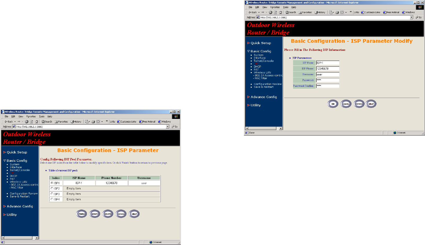
2. if you are an ADSL subscriber, you need specify that your personal ISP
PPPoE username and password to enable ADSL broadband access, in
here, click Basic Config, select ISP (as shown in Figure 3-7), In this
page, enter MODIFY button to setup the correct ISP parameters: ISP
Name, ISP Phone, PPPoE Username and PPPoE Password to (as
shown in Figure 3-8).
Hint: Ask your ISP for the correct settings.
Figure 3-7
3-8
Figure 3-8
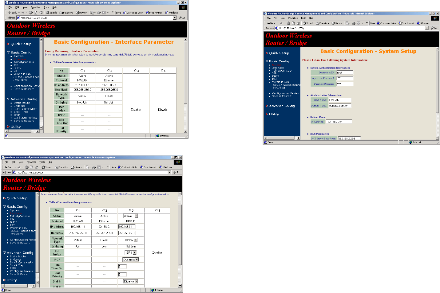
3. Click Basic Config, select Interface (as shown in Figure 3-9), In this
page, you can click radio button and enter MODIFY to choice which one
that you want to change it (as shown in Figure 3-10).
In interface 1, Make sure this wireless interface status is Active, enter
the Wireless interface IP (default is 192.168.1.1) and Wireless
interface Net Mask (default is 255.255.255.0) that are suitable for your
wireless network.
In interface 2, Make sure this Ethernet interface status is Active, and
specify the Ethernet IP address (default is 192.168.2.1) and Ethernet
Net Mask (default is 255.255.255.0) of the Ethernet interface.
In interface 3, Make sure this PPPoE interface status is Active, and
specify the Ethernet IP address (default is 192.168.2.1) and Ethernet
Net Mask (default is 255.255.255.0), choice the ISP index that your are
configured in step 1. After that, follow the default setting and Click the
OK button to return to the Interface Parameter window. Finally, you
need to click FINISH at the bottom of this page to complete the
modification of this page.
3-9
Figure 3-9
Figure 3-10
3-10
Figure 3-11
Hint: Make sure interface 4 within status Disable.
Hint: Choice the Network Type in every interfaces to enable NAT
service. For example, make sure PPPoE interface within Network Type
Global and others are Virtual, it means that every communications
through the PPPoE interface needs NAT transfer.
4. The RB supports PPPoE auto dial-up, please make sure your default
route is zero. In here, click Basic Config, and then select System as
shown in Figure 3-11. In the System Setup page, specify the Default
Route (Default is 192.168.2.254) is 0.0.0.0 and then click FINISH button
at the bottom of this page to complete the modification of this page.
3-11
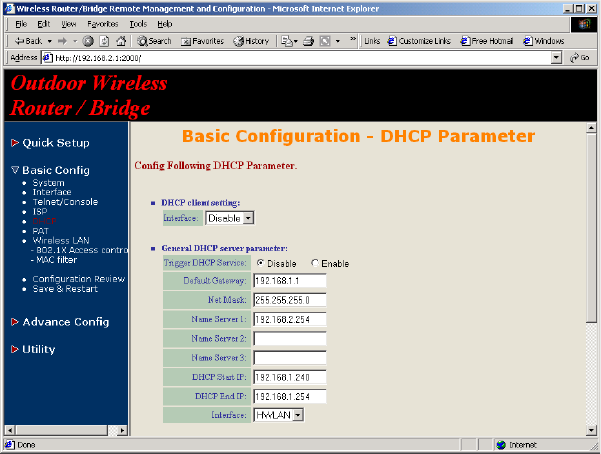
5. Click Basic Config, select DHCP (as shown in Figure 3-12) and make
sure the DHCP client service is Disable. After that, click FINISH at the
bottom of this page to complete the modification of this page.
Figure 3-12
3-12
3-2-3 Configure the RB as Root AP with dynamic IP
address Ethernet
3-2-3-1 Configure TCP/IP parameters
1. Click Advanced Config, select Bridging, and then click Disable for
Bridge Function as shown in Figure 3-6. After that, click FINISH at the
bottom of this page to complete the modification of this page.
2. Click Basic Config, select Interface (as shown in Figure 3-9), In this
page, you can click radio button and enter MODIFY to choice which
interface that you want to change it (as shown in Figure 3-10).
In interface 1, Make sure this wireless interface status is Active, enter
the Wireless interface IP (default is 192.168.1.1) and Wireless
interface Net Mask (default is 255.255.255.0) that are suitable for your
wireless network.
In interface 2, Make sure this Ethernet interface status is Active, and
other parameters will obtain automatically by DHCP from your network
environment.
Click the OK button to return to the Interface Parameter window.
Finally, you need to click FINISH at the bottom of this page to complete
the modification of this page.
Hint: Make sure interface 3 and 4 within status Disable.
Hint: In order to enable NAT service, choice the Network Type in the
interface Wireless and Ethernet. For example, make sure Ethernet
interface within Network Type Global and Wireless interface is Virtual,
it means that every communication through the Ethernet interface needs
to do NAT transfer.
3. Click Basic Config, select DHCP (as shown in Figure 3-12) and apply
the DHCP client service running on interface 2 (Ethernet interface),
After that, click FINISH at the bottom of this page to complete the
modification of this page.

3-13
3-2-4 Configure the RB as Root AP with static IP address
Ethernet
3-2-4-1 Configure TCP/IP parameters
1. Click Advanced Config, select Bridging, and then click Disable for
Bridge Function as shown in Figure 3-6. After that, click FINISH at the
bottom of this page to complete the modification of this page.
2. Click Basic Config, select DHCP (as shown in Figure 3-12) and make
sure the DHCP client service is Disable. After that, click FINISH at the
bottom of this page to complete the modification of this page.
3. Click Basic Config, select Interface (as shown in Figure 3-9), In this
page, you can click radio button and enter MODIFY to choice which
interface that you want to change it(as shown in Figure 3-10).
In interface 1, Make sure this wireless interface status is Active, enter
the Wireless interface IP (default is 192.168.1.1) and Wireless
interface Net Mask (default is 255.255.255.0) that are suitable for your
wireless network.
In interface 2, Make sure this Ethernet interface status is Active, and
specify the Ethernet IP address (default is 192.168.2.1) and Ethernet
Net Mask (default is 255.255.255.0) of the Ethernet interface.
Click the OK button to return to the Interface Parameter window.
Finally, you need to click FINISH at the bottom of this page to complete
the modification of this page.
Hint: Make sure interface 3 and 4 within status Disable.
Hint: In order to enable NAT service, choice the Network Type in the
interface Wireless and Ethernet. For example, make sure Ethernet
interface within Network Type Global and Wireless interface is Virtual,
it means that every communication through the Ethernet interface needs
to do NAT transfer.
4. Click Basic Config, and then select System as shown in Figure 3-11.
In the System Setup page, specify the Default Route (Default is
192.168.2.254) as the IP Address of the ADSL/Cable modem connected
to the AP or the IP Address of the Gateway in your LAN environment,
and Specify at least one IP address of the DNS parameter (Default
DNS server 1 is 192.168.2.254) provided by your ISP in the DNS server
parameter and then click FINISH button at the bottom of this page to
complete the modification of this page.
3-14
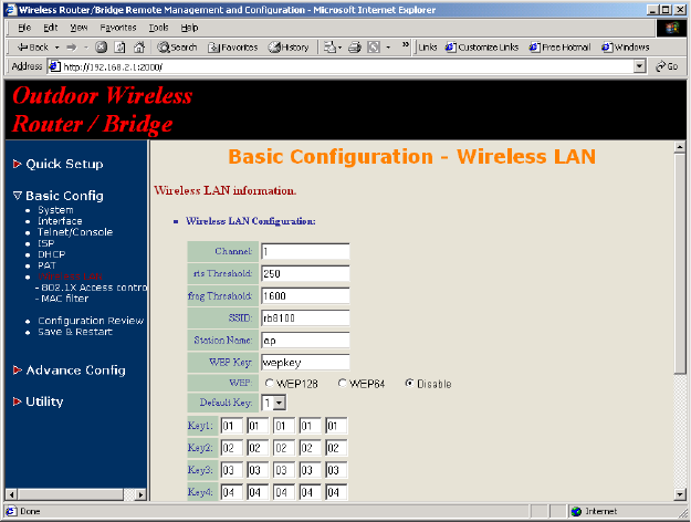
3-2-4 Configure Wireless related parameters
Configure IEEE 802.11b WLAN parameters (as shown in Figure 3-13)
Click Basic Config, select Wireless LAN page. In here, enter the Channel
(default is 1), rts Threshold (default is 250), frag Threshold (default is
1600), SSID (default is rb8100) and Station Name (default is ap) that are
suitable for your radio network and then you can clicked radio button to
disable WEP or enable 64/128 bit WEP services (default is disable), if
WEP is enabled, you must input corresponded Default Key index and WEP
Key. After that, click FINISH at the bottom of this page to complete the
modification of this page.
Figure 3-13
3-15
3-2-5 Configure the RB as Remote Extension Bridge
The RB series can easy build out Point-to-Point, Point-to-Multipoint wireless
backbone infrastructure, you can configure your RB as the Remote
Extension Bridge that connect to the Root RB.
1. Configure the operation role of this RB (as shown in Figure 3-14)
Click Quick Config, select Remote Extension Bridge to setup this RB
that play the Remote Bridge role and then click NEXT at the bottom of
this page to complete the modification of this page.
Figure 3-14
3-16
2. Configure TCP/IP parameters on Wireless (as shown in Figure 3-15)
In this page, enter the Wireless interface IP (default is 192.168.1.1)
and Wireless interface Net Mask (default is 255.255.255.0) that are
suitable for your wireless network, and specify the Default Gateway
(Default is 192.168.2.254) as the Wireless IP Address of the Root RB.
After that, specify the IP address of the DNS servers provided by your
ISP in the DNS server (Default is 192.168.2.254) parameter.
Hint: Designed your network infrastructure and assigned the correct IP
address for the Root RB and the Extension RB.
Figure 3-15
3. Configure TCP/IP parameters on Ethernet
Specify the Ethernet IP address (default is 192.168.2.1) and Ethernet
Net Mask (default is 255.255.255.0) of the Ethernet interface that are
suitable for your Ethernet network. At finally, click NEXT at the bottom of
this page to complete the modification of this page.
4. Configure Wireless parameters (as shown in Figure 3-16)
3-17
Hint: Make sure the SSID parameter is same with the configuration of
the Root RB.
In this page, enter the Channel (default is 1), rts Threshold (default is
250), frag Threshold (default is 1600), SSID (default is rb8100) and
Station Name (default is ap) that are suitable for your radio network
and then you can clicked radio button to disable WEP or enable 64/128
bit WEP services (default is disable), if WEP is enabled, you must
input corresponded Default Key index and WEP Key. After that, click
NEXT at the bottom of this page to complete the modification of this
page.
Figure 3-16
3-18
5. Preview the configured setting of this RB (as shown in Figure 3-17)
This page will present the current settings of the RB to system
administrator, the operator can easy to view all running configuration in
here. After that, click Save button to store the changes to the RB.
Figure 3-17
6. Enable DHCP client on this Extension RB
Sometimes, the operator may use DHCP to manage the network. In
here, you can enable DHCP client services on wireless interface. You
can click Basic Config, select DHCP (as shown in Figure 3-12) and
apply the DHCP client service running on interface 1 (Wireless
interface), After that, click FINISH at the bottom of this page to complete
the modification of this page.
7. Enable NAT
Sometimes, the operator may implement NAT on the network. In here,
you can click Basic Config, select Interface (as shown in Figure 3-9),
in this page, you can click radio button and enter MODIFY to choice
3-19
which interface that you want to change it (as shown in Figure 3-10).
In order to enable NAT service, choice the Network Type in the
interface Wireless and Ethernet. For example, make sure Ethernet
interface within Network Type Virtual and Wireless interface is Global,
it means that every communication through the Wireless interface
needs to do NAT transfer.
3-20
3-3 Security
3-3-1 WEP encryption
1. Click Basic Config, select Wireless LAN page, and configure it to
disable or enable 64/128 bit WEP services (default is disable) as
shown in Figure 3-13.
2. Key in the WEP Key and specify which WEP Key id you want to use it.
After that, click FINISH at the bottom of this page to generate the real
WEP key complete the modification of this page.
Hint: If you enable WEP services on RB, all of the communication between
stations to RB will be encrypted. You must make sure all wireless client and
RB with the same WEP key.
Figure 3-18
3-21
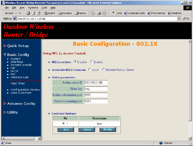
3-3-2 IEEE 802.1x Access Control
You can configure Authenticator on RB:
1. Click Basic Config, select 802.1X Access Control page, and choice
the IEEE 802.1x services is Enable or Disable. (as shown in Figure 3-
19).
Figure 3-19
2. The RB supporting authentication which based on two kinds of user
information base, Local User Database or Remote Radius Servers.
You can specify which user database you want to use.
3. You can specify the username/password of a accessible 802.1x user. All
user information entries in the Local User Database are permitted to
connect to the RB. You can also click ADD, DELETE, MODIFY button to
maintain this User Information table.
4. Some Radius server implements EAP authentication, like Microsoft
3-22
Windows 2000 server. To set up the Radius server and RB for
authentication, you must specify the Radius server IP address, Share
key between RB and Radius server, authentication port and
accounting port on this Radius server.
5. Click FINISH at the bottom of this page to complete the modification of
this page.
3-23
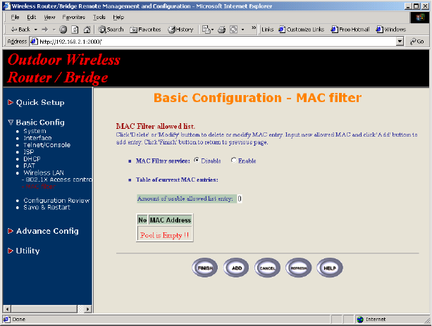
3-3-3 MAC based Access Control
1. Click Basic Config, select MAC Filter page, and choice the MAC Filter
services is Enable or Disable. (as shown in Figure 3-20)
2. You can specify the MAC address of a wireless client station. All MAC
entries in the MAC address table are permitted to connect to the RB.
You can also click ADD, DELETE, MODIFY button to maintain this MAC
address table. After that, click FINISH at the bottom of this page to
complete the modification of this page.
Figure 3-20
3-24
3-4 Configure DHCP server
Sometimes, the operator want to managing a large TCP/IP network requires
maintaining accurate and up-to-date IP address and domain name
information. In this situation, it needs manually configure and enable the
DHCP server service
1. Click Basic Config, select DHCP (as shown in Figure 3-12) and
Enable the DHCP server service (Default is Disable).
2. Specify the DHCP server parameters (Assign Gateway, Assign
Subnet Mask, Assign DNS server, DHCP Start IP address, DHCP
End IP address and Apply Interface) to allow any DHCP client to
acquire the IP information.
Assign Gateway: Configure the default router for the client.
Assign Subnet Mask: Configure the subnet for the client.
Assign DNS Server: Configure the DNS servers IP for the client.
DHCP Start IP address, DHCP End IP address: Configure the DHCP
IP address pool for the client.
Apply Interface: Enable DHCP server service on Wireless or Ethernet
interface.
3. After that, click FINISH at the bottom of this page to complete the
modification of this page.
Hint: The operator must to configure correct network settings in Gateway
and DNS server of your wireless stations/Extension RBs/Ethernet clients to
surf the Internet.
3-25
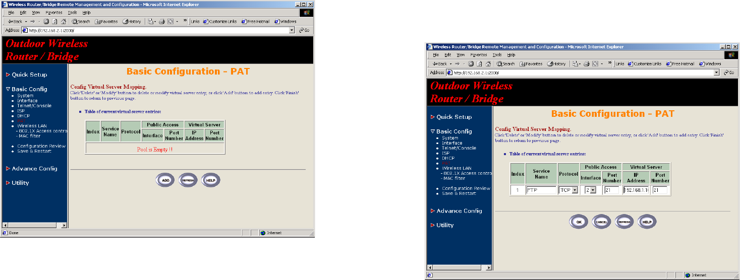
3-5 Configure Virtual Server
Sometimes, the operator can expose the internal servers on the local
intranet to the public Internet. For this, you must create the Virtual Server
Mapping for these invisible internal servers.
1. Click Basic Config, select PAT (as shown in Figure 3-21) and click
ADD, DELETE or MODIFY button to change to configure Virtual Server
Mapping page (as shown in Figure 3-22). In this page, you can maintain
this Virtual Server Mapping pool (Default Virtual Server Mapping
pool is empty) to enable the internal servers.
Figure 3-21
2. In configure Virtual Server Mapping page, you must specify some
parameters (Service Name, Protocol, Public Access Interface,
Public Access Port number, Virtual Server IP address and Virtual
Server Port Number) to allow Internet user to access the Internal
servers.
Service Name: Alias name of this internal server, such as FTP.
Access Interface: Indicate the translation occurs on which interface
3-26
(Wireless interface, NO. 1/Ethernet interface, NO. 2), such as NO. 2.
Protocol: Indicate which protocol (TCP/UDP) you want to translate from
outside to internal server, such as TCP.
Public Access Port number: Indicate which socket port (1 ~ 65535)
you want to translate from outside to internal server, such as 21.
Virtual Server IP address: Specify the private IP address of the internal
server, such as 192.168.1.100.
Virtual Server Port number: Specify the socket port (1 ~ 65535) of the
internal server, such as 21.
3. After that, click FINISH at the bottom of PAT page to complete the
modification for the Virtual Server Mapping.
Figure 3-22
3-27
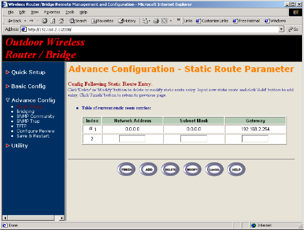
3-6 Configure Routing Table
1. Click Advence Config and select the Static Route page. This page (as
shown in Figure 3-23) will present the current configuration for the
routing table. You can also click ADD, DELETE or MODIFY button to
maintain the Static Routing table (Default Routing table only contain
single routing entry: Default Route entry).
2. Every Route entry contains three parameters: Network Address,
Subnet Mask and Gateway.
Network Address and Subnet Mask: Specify the destination network.
Gateway: Indicate the forward gateway.
3. After that, click FINISH at the bottom of this page to complete the
modification of this page.
Hint: The operator must to configure correct routing settings following the
network infrastructure.
Figure 3-23
3-28
3-7 Configure Bridge
1. Click Advence Config and select the Bridging, and then click Enable
for Bridge Function as shown in Figure 3-6. In the Bridging
Parameter window, enter the IP Address (default is 192.168.2.1) and
Subnet Mask (default is 255.255.255.0) that are suitable for your
network domain.
2. You can specify the MAC address of a Wireless/Ethernet client. All MAC
entries in the MAC address table are Permitted/Blocked/Learning to
connect to the RB. In here, you can also click ADD, DELETE, MODIFY
button to maintain this MAC address table.
3. After that, click FINISH at the bottom of this page to complete the
modification of this page.
3-29
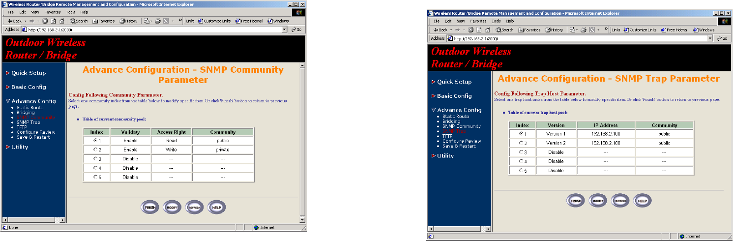
3-8 Configure SNMP
1. Click Advence Config and select the SNMP Community page. This
page (as shown in Figure 3-24) will present the current accessible
snmp communities and correspond Read/Write privilege. After that,
click FINISH at the bottom of this page to complete the modification of
this page.
2. Click Advence Config and select the SNMP Trap page. In this page,
you can specify the SNMP Trap host and correspond SNMP Trap
Community in this page. After that, click FINISH at the bottom of this
page to complete the modification of this page.
Figure 3-24
3-30
3-9 Configuration Review and Apply the New Settings
1. Click Basic Config or Advence Config and select the Configuration
Review page. This page (as shown in Figure 3-25) will present the
current configuration settings the operator has made.
2. Click Basic Config or Advence Config and select the Save & Restart
page. In this page, you can click the SAVE button to apply the new
configuration settings and click the Restart button to take effect the
previous configuration changes.
Hint: It needs to take about 10 seconds for the RB to complete the restart
process.
Figure 3-25
3-31
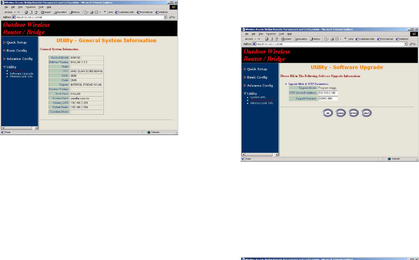
3-10 Utility
3-10-1 System Info
Click Utility, select System Info page (as shown in Figure 3-26), you can
view some system information on this, such as Model Name, Software
Version, CPU and RAM, …etc.
Figure 3-26
3-32
3-10-2 Software Upgrade
1. Click Utility, select Software Upgrade page (as shown in Figure 3-27),
and then you can use TFTP to upgrade your RB. In here, you must
specify the TFTP server IP and the File Name that you want to upgrade.
After that, click OK button to start the TFTP upgrade process.
2. If the upgrade process is success, the RB will apply the new settings
and start rebooting right away.
Hint: You must set up a TFTP server and this server must contain one
newest image.
Figure 3-27
3-33
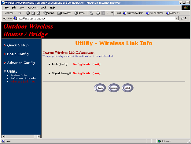
3-10-3 Wireless Link Info
1. Click Utility, select Wireless Link Info page (as shown in Figure 3-28),
and then you can view the Link Quality and the Signal Strength of this
wireless connection.
2. The Link Quality and the Signal Strength are valid only in the role of
Extension RB. In here, you can also see the quality level for this
wireless connection.
Figure 3-28
4-1
Chapter 4 Command Line Interface
The RB is designed to operate as shipped from the factory without any
special set-up. However, it has many options and parameters that can be
changed if users have special requirements. Most of the management
functions can be accessed using TCP/IP protocol, it also configured by
Telnet/Console.
4.1 Telnet configuration
The user can use a LAN attached (wired or wireless) computer to configure
the RB through using a Telnet session on a LAN attached computer. To use
the Telnet session simply open a Telnet window using the IP address which
has been assigned to the RB.
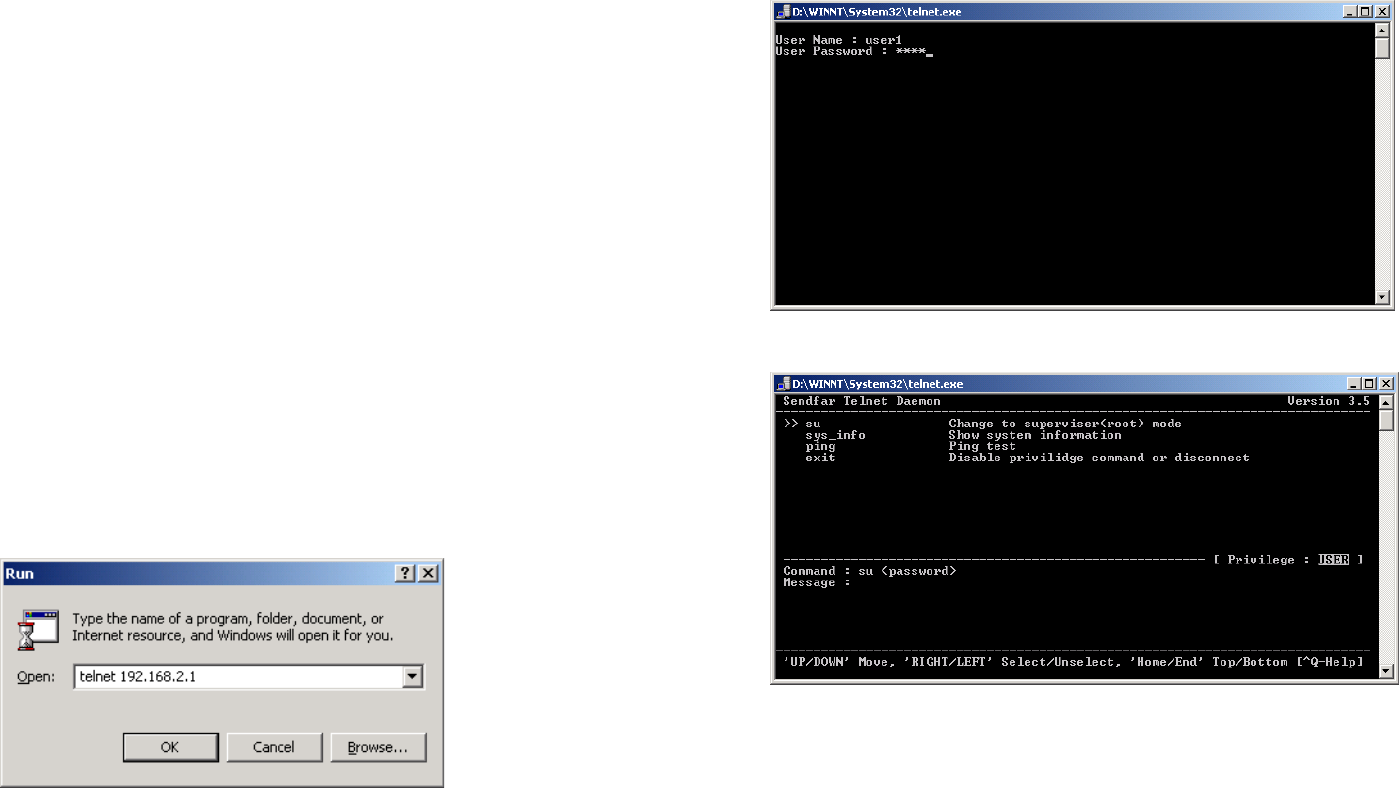
1. Click Start button, select Run to open the Run dialog box. Enter telnet
192.168.2. 1(default terminal type of Telnet is VT100, default IP address
of the RB is 192.168.2.1). Then click OK as shown in Figure 4-1.
Figure 4-1
2. In the Telnet window, enter the User Name and User Password as
shown in Figure 4-2 (default User Name and User Password is user1
and test) to see the main screen of Telnet user interface as shown in
Figure 4-3.
4-2
Figure 4-2
Figure 4-3
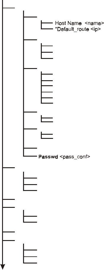
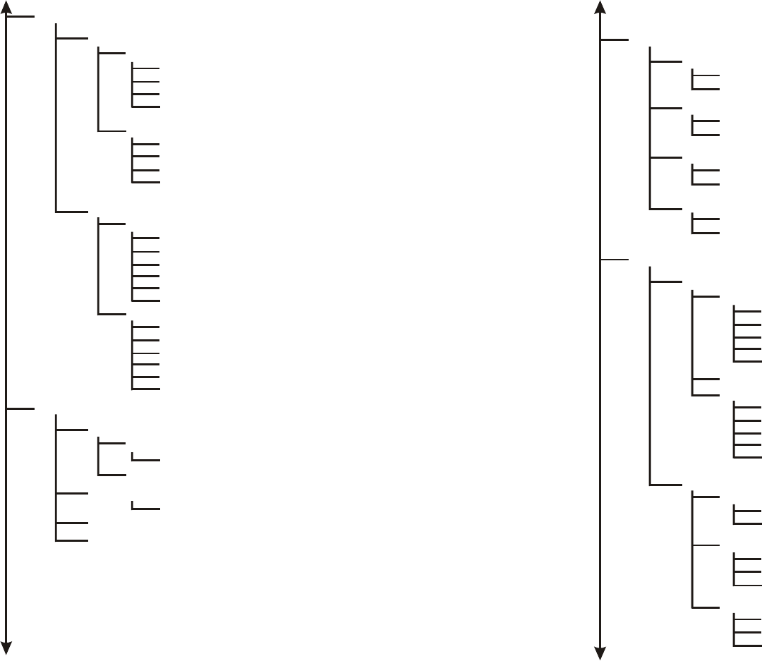
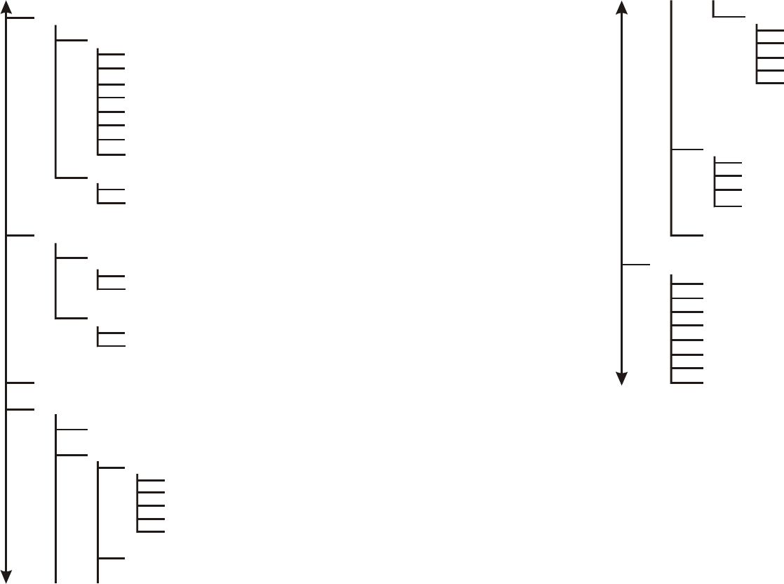
1. The structure of menu tree is shown in Figure 4-4. Users can use the
following keys to select the parameter you want to change or add. The
definition of the parameters is described in Table 4-1 to Table 4-14.
y Up/Down or i/k key: move the cursor up/down to the specific item.
y Right or l or Enter key: select the item or enter to sub-menu. Left or j
key: return to previous menu page.
y Home or Ctrl-A: move the cursor to the first item of the menu page.
y End or Ctrl-E: move the cursor to the last item of the menu page.
y Ctrl-Q or F1: Show the help page.
4-3
Note 1: * denote the function is displayed after enable configuration mode
is enabled.
Note 2: In item su, type default password root to enter the supervisor
configuration mode.
4-4
Figure 4-4
Su
Setup
System
Ian
Address <ip> <netmask>
Attrib <Enable | Disable> <Global | Virtual>
Bridge <Enable | Disable>
Wan
Address <ip> <netmask>
link - Type <Disable | Ethernet | PPP >
Attrib <
| PPPoE
Enable | Disable> <Global | Virtual>
ether_interface <interface>
Bridge <Enable | Disable>
ISP <ISP Index> <idle disconnect time> <Dial priority>
ISP
*ISP_ profile <ISP name> <ISP destination>
*account - profile <Access account> <Passwd>
Configuration
<name> <pass_conf> <ip>
Upgrade
image
webimage
bootstrap 2
<ip> <file>
<ip> <file>
<ip> <file>
*Enable
Monitor
Wan
Config_access [Generic| Profile | Pool]
(CR)
Passwd <
pass_conf>
*System
OP _ mode <Router | Bridge | Host>
hostname <name>
default _ route <ip>
PPP
Peer_address <ip>
User_profile <name> <pass_set0>
4-5
Figure 4-4
*Interface
1
address <ip> <netmask>
link type <Disable | Ethernet>
attrib <Disable | Enable> <Global | Virtual>
bridge <Disable | Enable>
2
address <ip> <netmask>
link type <Disable | Ethernet>
attrib <Disable | Enable> <Global | Virtual>
bridge <Disable | Enable>
lan
wan
1
address <ip> <netmask>
link type <Disable | Ethernet | PPP | PPPoE>
attrib <Disable | Enable> <Global | Virtual>
bridge <Disable | Enable>
ether_interface <interface>
ISP <ISP Index> <dialup timeout> <Dial priority>
2
address <ip> <netmask>
link type <Disable | Ethernet | PPP | PPPoE>
attrib <Disable | Enable> <Global | Virtual>
bridge <Disable | Enable>
ISP <ISP Index> <Idle disconnect time> <Dial priority>
ether_interface <interface>
*PPP
User_edit
modify (5)
profile <name> <pass_set0>
delete
address_pool
ip_pool <ip> <1~127>
authenticate
<Userpool | RADIUS> <Userpool | RADIUS>
assign_address
<Address_Pool | RADIUS> <Address_Pool | RADIUS>
4-6
Figure 4-4
*IP _ share
add
protocol <TCPIUDP>
port <1~65534>
interface <1~2>
server <ip> <1~65534>
name <name>
pat
dalete
<1~10>
modify (10)
protocol <TCPIUDP>
port <1~65534>
interface <1~2>
server <ip> <1~65534>
name <name>
nat
local
range <1~5> <ip> <1~253>
delete <1~5>
global
range <1~5> <ip> <1~253>
interface <1~5> <1~5>
delete <1~5>
fixed
modify <1~128> <ip> <ip>
interface <1~128> <1~5>
delete <1~128>
*ISP
1
isp - profile (ISP name) (destination string)
account - profile (name) (pass - set 1)
2
isp - profile (ISP name) (destination string)
account - profile (name) (pass - set 1)
3
isp - profile (ISP name) (destination string)
account - profile (name) (pass - set 1)
4
isp - profile (ISP name) (destination string)
account - profile (name) (pass - set 1)
4-7
Figure 4-4
*dhcp
service <Disable | Enable>
interface <1~2>
gateway <ip>
netmask <netmask>
ip range <ip> <number>
name server 1 <ip>
name server 2 <ip>
name server 3 <ip>
generic
fixed
add <mac> <ip>
delete
*snmp
community (5)
edit <Disable | Enable> <string> <Read_Only | Read_Write | Denied>
delete
trap (5)
edit <Disble | 1 | 2> <ip> <string>
delete
*tftp
<ip> <file>
*bridge
generic
<Disable | Enable> <ip> <netmask>
static
mac _ address <mac>
lan1_ port <Filter | Forward | Dynamic>
lan2 _ port <Filter | Forward | Dynamic>
wan 1 _ port <Filter | Forward | Dynamic>
wan 2 _ port <Filter | Forward | Dynamic>
add
delete (1~20)
4-8
Figure 4-4
modify (20)
mac _ address <mac>
lan1_ port <Filter | Forward | Dynamic>
lan2 _ port <Filter | Forward | Dynamic>
wan 1 _ port <Filter | Forward | Dynamic>
wan 2 _ port <Filter | Forward | Dynamic>
stp
module <Disable | Enable>
bridge <number>
lan _ port <1~2> <Disable | Enable> <number>
wan _ port <1~2> <Disable | Enable> <number>
activate _ stp
<CR>
WLAN
channel <1~14>
weprequired <Disable | Enable>
rts Threshold <0~3000>
frag Threshold <256^2346>
SSID <string>
station Name <string>
defaultkeyId <1~4>
defaultkeys <1~4> <hex>

4-9
Figure 4-4
*Show: Show the current configuration values
interface
PPP
ip _ share
dhcp
snmp
bridge
isp
run
*reset - default
write
reboot
su
sys info
Ping <ip> [1~65534| - t] [1~1999]
exit
configuration
max _ user <1~5>
telnet_port <1~65534>
console _ port <com 1 | com 2 >
user _ profile
add
attrib <13~30><command | Menu><VT100 | ANSI | LINUX | XTerm>
source <-1~10>
profile <name> <pass _ conf> <Level 1 | Level 2 | Level 3 | Unlimited>
delete (1~5)
attrib <13~30><command | Menu><VT100 | ANSI | LINUX | XTerm>
source <-1~10>
profile <name> <pass _ conf> <Level 1 | Level 2 | Level 3 | Unlimited>
legal - address
modify <1~10> <ip>
delete <1~10>
modify
attrib <13~30><command | Menu><VT100 | ANSI | LINUX | XTerm>
source <-1~10>
profile <name> <pass _ conf> <Level 1 | Level 2 | Level 3 | Unlimited>

Appendix - 1
Appendix A Specifications
General
Compatibility Fully interoperable with IEEE802.11b
compliant products
Regulation Certifications FCC Part 15, ETSI 300/328
Power Supply
Output: –48 VDC/0.7A (power over
Ethernet)
Input: 100/240 VAC; 50/60 Hz
Temperature Range -20 to 70 ℃ (operating)
-40 to 80 ℃ (storage)
Humidity (non-condensing) 5% to 95% typical
Surge Arrester 20KA Surge Current
Radio
Frequency Band 2.4 – 2.484 GHz
Radio Type Direct Sequence Spread Spectrum
(DSSS)
Modulation CCK (11, 5.5Mbps)
DQPSK (2Mbps)
DBPSK (1Mbps)
Operation Channels 11 for North America, 14 for Japan,
13 for Europe, 2 for Spain, 4 for France
RF Output Power 13dBm(ETS,FR) [ model: RB-8100E],
19dBm(FCC) [model: RB-8100]
RF Connector Proprietary N-type (Reverse Polarity)
Network Information
Ethernet Interface 10-Base T (RJ45)
IP Sharing Supports NAT
Roaming Seamless roaming (IEEE802.11b
compliant)
Security 64/128-bit WEP data encryption
Appendix - 2
Management
Local Configuration RS-232 serial port
Remote Configuration HTTP, Telnet, SNMP
Firmware Upgrade Upgrade via Serial Interface or TFTP
IP Auto-configuration Supports DHCP server
Physical Specifications
Dimensions 245(L) mm x 200(W) mm x 70(H) mm
Weight 2100 g

Appendix - 3
Appendix B Default Settings
B-1 Basic Configuration
B-1-1 System (as shown in Table B-1)
Parameter Description Default Value
Supervisor ID Supervisor’s identity code root
Supervisor Password Supervisor’s password root
Password Confirm Confirm the password again root
Host Name Host name for the AP HWLAN
Domain Name Domain name for the AP senfar.com.tw
Default Route IP
Address
IP address of the gateway for
default route when TCP/IP
filtering
192.168.2.254
DNS Server Parameter
DNS Server 1 Address
DNS Server 2 Address
DNS Server 3 Address
IP addresses of the DNS Servers
of your Local ISP 192.168.2.254
Table B-1
B-1-2 Interface (as shown in Table B-2)
Parameter Description Default Value
Interface No.
No.1 Wireless Interface
No.2 Ethernet Interface
No.3 PPPoE Interface
No.4 PPP Interface
Note:
1. No.3 is effective
only when No.2 is
Active.
2. Default No.3 &
No. 4 is Disable
Status Enable or disable the
Corresponding interface Active
IP address
IP address of the corresponding
interface. The user can use a
LAN attached (wired or wireless)
No.1: 192.168.1.1
No.2: 192.168.2.1
No.3: 192.168.3.1
Appendix - 4
computer to configure the AP
through using a web browser
or telnet program on a LAN
attached computer.
No.4: 192.168.4.1
Net Mask
Consists of four sets of digits
that help divide a network into
sub-networks and simplify
routing and data transmission
No.1:255.255.255.0
No.2:255.255.255.0
No.3:255.255.255.0
No.4:255.255.255.0
Network Type
Select the network type for NAT
function.
Virtual <-> Global: NAT enable
Global <-> Global: NAT disable
Virtual <-> Virtual: NAT disable
No.1: Virtual
No.2: Global
No.3: Global
No.4: Global
Bridging
Shows the corresponding
interface that joins to form a
bridge
No.1: Not Join
No.2: Not Join
No.3: Not Join
No.4: Not Join
ISP Index Select the ISP index given in
the ISP pool ISP1
IPCP
Select IP Control Protocol
(Static or dynamic) for
PPP/PPPoE interface
Dynamic
Idle Time Out (min) Cancel the dial if not connected
within this period 3min
Dial Priority Set the dial-up priority of the
corresponding interface
PPPoE: 3
PPP: 2
Dial-in
Enable or disable the dial-in
function of the corresponding
interface
Disable
Dial-in Authentication
Selects the authentication
protocol for the corresponding
dial-in interface
None
Table B-2

Appendix - 5
B-1-3 Telnet/Console (as shown in Table B-3)
Parameter Description Default Value
Maximum User
Set the maximum number of
the users that can login the AP
through Telnet session at the
same time
2
Telnet Port The port number for Telnet
Program 23
Console Port The communication port that is
used to login the AP COM1
ID Number Index for Telnet users 1
User Name User name for Telnet session user1
Privilege Select the user’s privilege level
for Telnet session Unlimited
Max. Screen Line Set the maximum number of
lines displayed on the screen 24
Show Mode
Select the type of display for
Telnet session
(Command/Menu mode)
Menu
Keyboard Type Select the type of the keyboard
for Telnet session VT100
Table B-3
B-1-4 Telnet/Console (as shown in Table B-4)
Parameter Description Default Value
ISP Name Name of Internet Service
Provider ISP-1
Phone Number
The phone number that is used
to dial up your ISP
Note: The phone number must
enter direct line phone number
12345678
Username The user name used to login ISP user
Password The password used to login ISP pass
Table B-4
B-1-5 DHCP (as shown in Table B-5)
Parameter Description Default Value
Appendix - 6
DHCP Client Setting
Enable or disable the specified
interface to obtain an IP address
automatically
Disable
Trigger DHCP Service
Enable or disable automatic IP
address assignment to wireless
stations
Disable
Default Gateway
IP address of the gateway for
default route when TCP/IP
filtering
192.168.1.1
Net Mask
Consists of four sets of digits
that help divide a network into
sub-networks and simplify
routing and data transmission
255.255.255.0
Name Server IP address of the DNS host 192.168.2.254
DHCP Start IP IP starting address 192.168.1.240
DHCP End IP IP ending address 192.168.1.254
Interface Select the interface to provide
DHCP service HWLAN
Fixed Host Entry
Define a fixed Ethernet-to-IP
address mapping to limit the
client station with the Ethernet
address to get the IP address
Table B-5
B-1-6 Virtual Server Mapping (as shown in Table B-6)
Parameter Description Default Value
Service Name Specify the service for public
access NULL
Protocol Select a protocol for public
access NULL
Public Access –
Interface
Select an interface for public
access NULL
Public Access – Port
Number
Specify the port number of the
interface for public access NULL
Virtual Server – IP Specify the IP address of the NULL

Appendix - 7
Address virtual server
Virtual Server – Port
Number
Specify the port number of
internal virtual server NULL
Table B-6
B-1-7 NAT (Network Address Translation) (as shown in Table B-7)
Parameter Description Default Value
Local IP Address
Pool – Base IP Address
IP starting address of local IP
address NULL
Local IP Address
Pool –Count Number of local IP address NULL
Global IP Address
Pool – Base IP Address
IP starting address of global IP
address NULL
Global IP Address
Pool – Count Number of global IP address NULL
Global IP Address
Pool – Interface
Specify the interface as global
IP address NULL
Fixed IP Address
Mapping – Local/Global
IP Address
Define a local and global IP
address pair for network
address translation
NULL
Fixed IP Address
Mapping – Interface
Specify the interface for
network address translation NULL
Table B-7
B-1-8 Wireless LAN (as shown in Table B-8)
Parameter Description Default Value
Regulatory Domain Define the regulatory domain to
Which this NIC may be deployed 1
Channel The operating radio frequency
channel for the AP 11
RTS Threshold Set RTS (Request To Send)
threshold value 250
Fragmentation
Threshold
Set fragmentation threshold
value 1600
SSID Wireless LAN service area rb8100
Appendix - 8
identifier of the AP (case
sensitive)
Station Name Shows the name of the AP ap
WEP
Enable or disable 64-bit WEP
(Wired Equivalent Privacy) key
to encrypt data
Disable
Default Key
Select a WEP key to encrypt
each frame transmitted from
the radio using one the of the
Keys from the Key Panel
1
Key Panel
When you use WEP to
communicate with the other
wireless clients, all the wireless
devices in this network must
have the same encryption key
or pass phrase.
Note: each key must consist
of hex digits, it means that
only digit 0 -9 and letters A-F
are valid entries. If entered
incorrectly, program will not
write keys to a driver.
Table B-8
B-1-9 Bridging (as shown in Table B-9)
Parameter Description Default Value
Bridging Function Enable or disable bridging
Function
Enable
IP Address
IP Address of the AP when in
Bridging mode. The user can
use a LAN attached (wired or
wireless) computer to configure
the AP through using a web
browser or telnet program on a
LAN attached computer.
192.168.2.1
Subnet Mask Consists of four sets of digits 255.255.255.0

Appendix - 9
that help divide a network into
sub-networks and simplify
routing and data transmission
Operation mode
Enable or disable the operation
mode
Enable
Enable
Disable
Disable
MAC Address MAC address to be considered
in forward/filter policy
00-00-00-00-00-00
Interface
Select Filter(always block the
frames), Forward(always
forward the frames) or
Dynamic(forward the frames if
the MAC address exists) to the
corresponding interface
1. Filter
2. Filter
3. ---
4. ---
Table B-9
B-1-10 SNMP Community (as shown in Table B-10)
Parameter Description Default Value
Validity
Enable or disable the function
of the corresponding community
index
Enable
Access Right
Select the access right
(Deny/Read/Write/Create) for
SNMP Manager
Read
Community
Specify the type of community
(public or private) for SNMP
Manager
Public
Table B-10
B-1-11 SNMP Trap (as shown in Table B-11)
Parameter Description Default Value
Index Enable or disable the activity of
the corresponding community
Enable
Version Select or disable the SNMP Version1
Appendix - 10
Version
Version 1: MIB1
Version 2: MIB2
IP Address
Specify the IP address of the
SNMP Manager for SNMP Trap
Report
192.168.2.100
Community
Specify the type of community
(public or private) for SNMP
Manager
Public
Table B-11
B-1-12 Software Upgrade (as shown in Table B-12)
Parameter Description Default Value
TFTP Server IP
Address
Specify the IP address of the
TFTP server to upgrade the
firmware of the AP
192.168.2.100
Upgrade Filename
Specify the filename of
requested firmware
stored in TFTP server
Soho.bin
Table B-12
Appendix - 11
Appendix C Regulatory Compliance
Information
Radio Frequency Interference Requirements
This device complies with Part 15 of FCC Rules and Canada RSS-210.
Operation is subject to the following conditions:
1. This device may not cause harmful interference.
2. This device must accept any interference received, including interference that
may cause undesired operation.
This transmitter must not be co-located or operating in conjunction with any other
antenna of transmitter.
Interference Statement
This equipment has been tested and found to comply with the limits for a Class B
digital device pursuant to Part 15 of the FCC Rules and Regulation. These limits are
designed to provide reasonable protection against harmful interference in a
residential installation. This equipment generates, uses, and can radiate radio
frequency energy and, if not installed and used in accordance with the instruction
manual, may cause harmful interference to nearby TV’s, VCR’s, radio, computers, or
other electronic devices. To minimize or prevent such interference, this equipment
should not be placed or operated near these devices. If interference is experienced,
moving the equipment away from them will often reduce or eliminate the
interference.
However, there is no guarantee that interference will not occur in a particular
installation. If the equipment does cause harmful interference to radio or television
reception, which can be determined by turning the equipment off and on, the user is
encouraged to try to correct the interference by one or more of the following
measures:
Re-orient or relocate the receiving antenna.
Increase the separation between the equipment and receiver.
Appendix - 12
Connect the equipment into an outlet on a circuit different from that which the
receiver is connected.
Consult the dealer or an experienced radio/TV technician for help.
Professional Installation
Per the recommendation of the FCC, the installation of high gain directional antenna
to the system, which are intended to operated solely as a point-to-point system and
whose total power exceeds +36dBm EIRP, require professional installation. It is the
responsibility of the installer and the end user that the high power systems are
operated strictly as a point-to-point system.
Systems operating as a point-to-multipoint system or use non directional antennas
cannot exceed +36dBm EIRP power requirement under any circumstances and do
not require professional installation.
"The antennas used for this transmitter must be fixed-mounted on outdoor
permanent structures with a separation distance of at least 2 meters
from all persons"