Senao Co AT53V114 Wireless Cardbus Adapter User Manual 5354CB Manual
Senao International Co Ltd Wireless Cardbus Adapter 5354CB Manual
UserManual.wiki
>
Senao Co
>
AT53V114 User Manual
>
Users Manual
Contents
1.
DoC Statement
2.
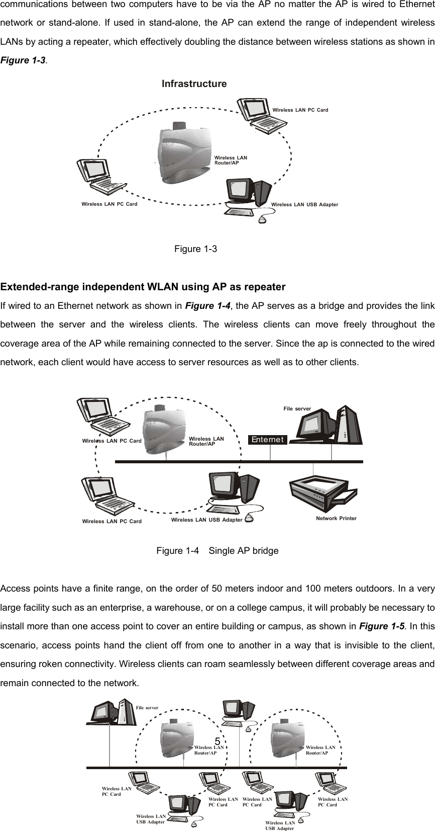
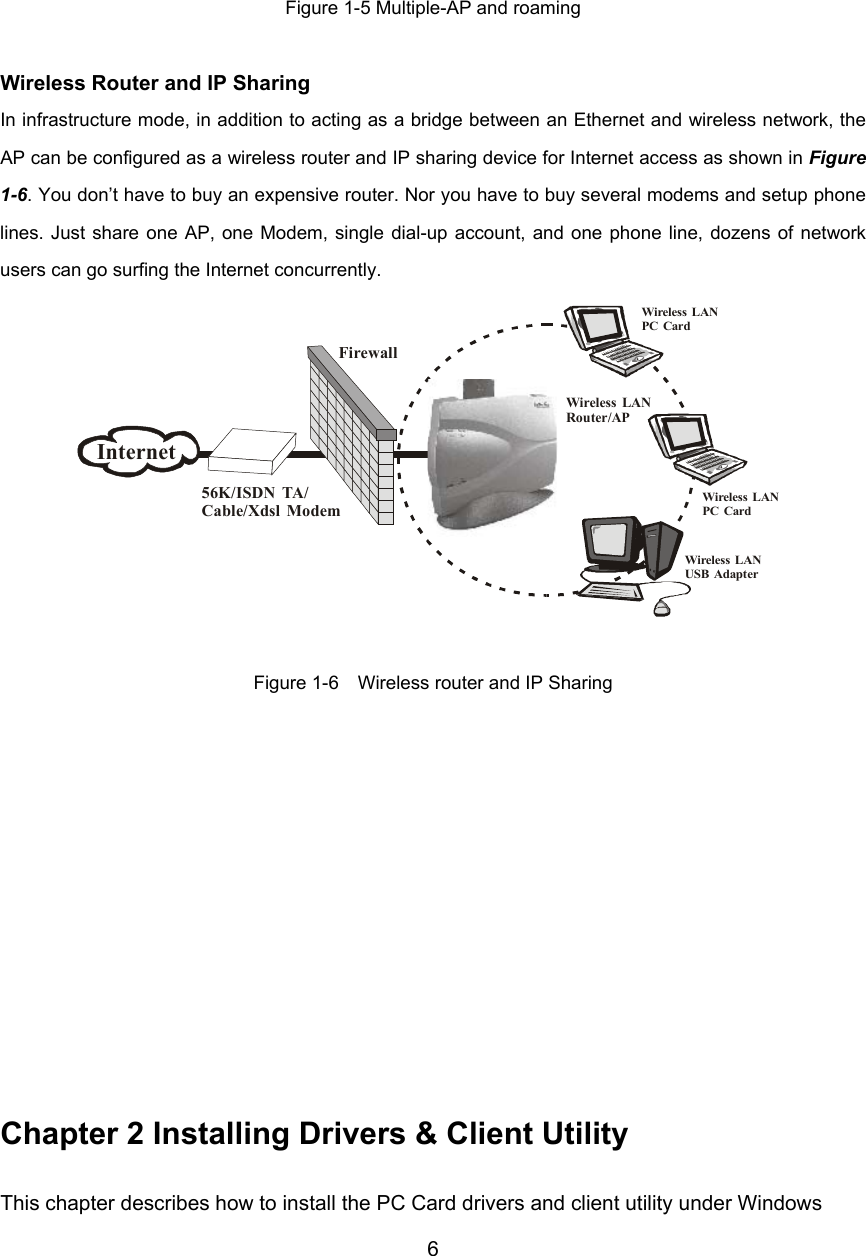
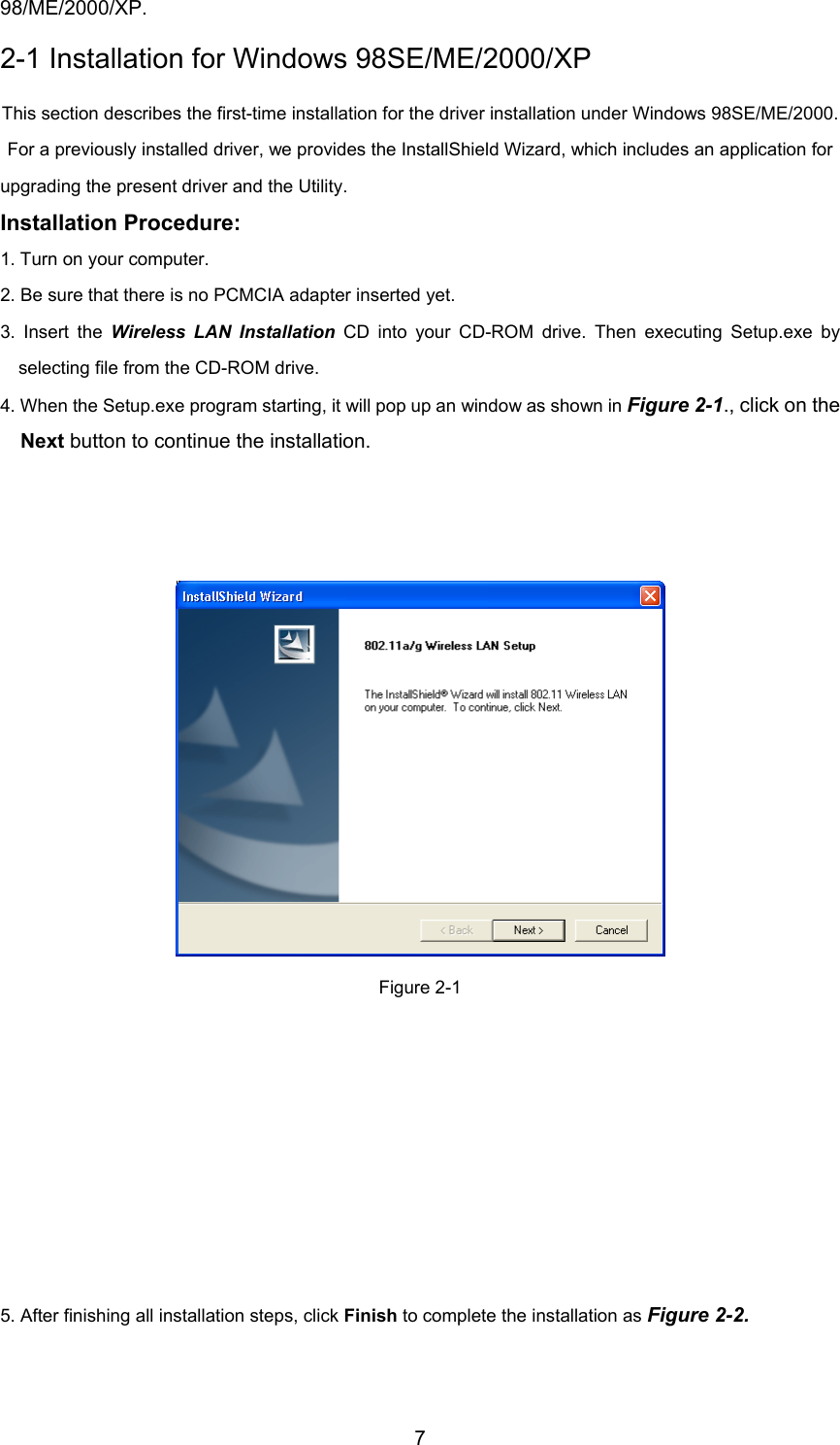
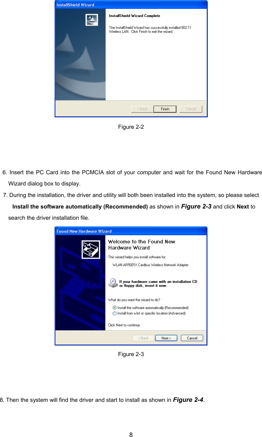
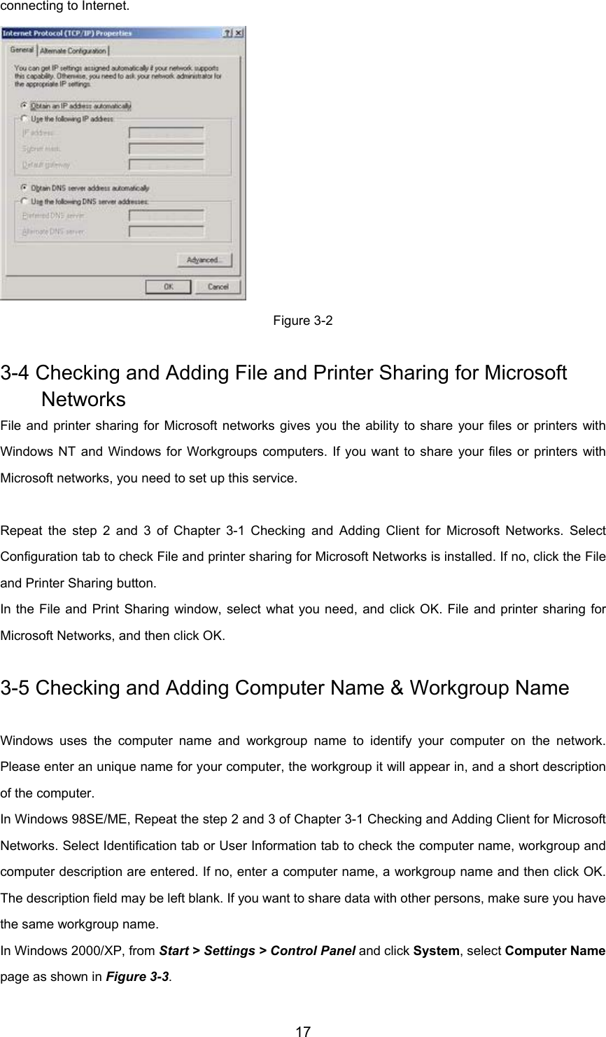
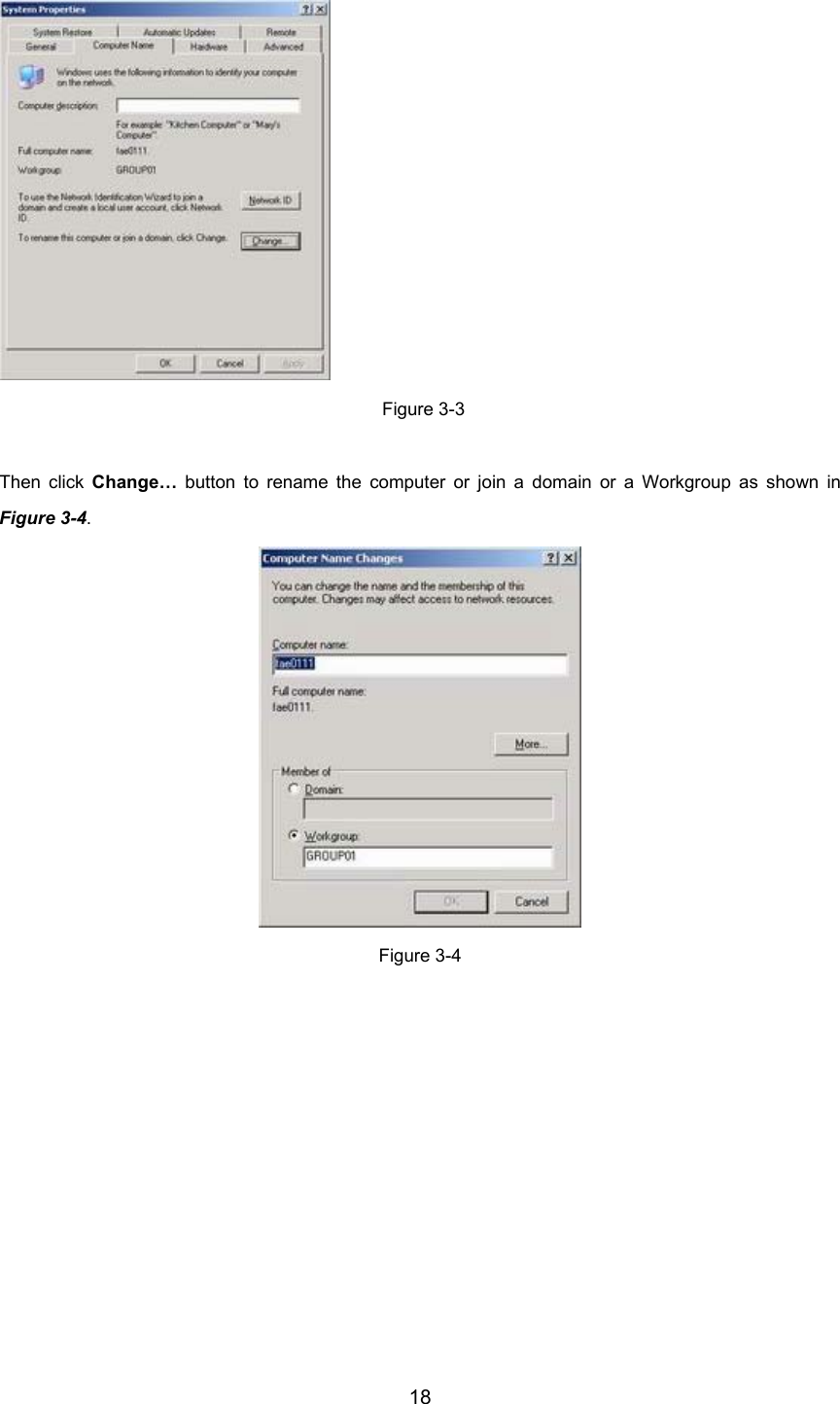
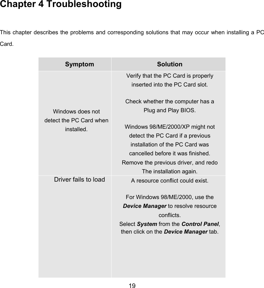
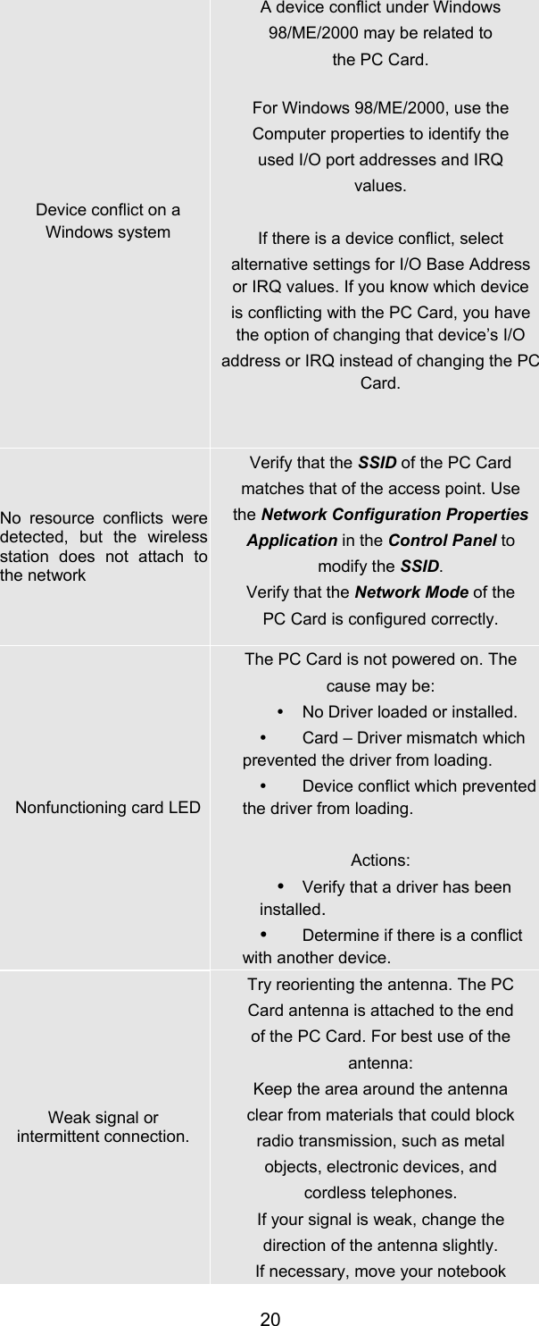
Users Manual
3.
Revised Manual
Users Manual
Navigation menu
Upload a User Manual
Namespaces
Wiki Guide
HTML
PDF
Info
Views
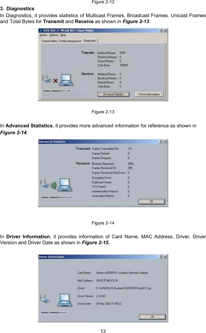
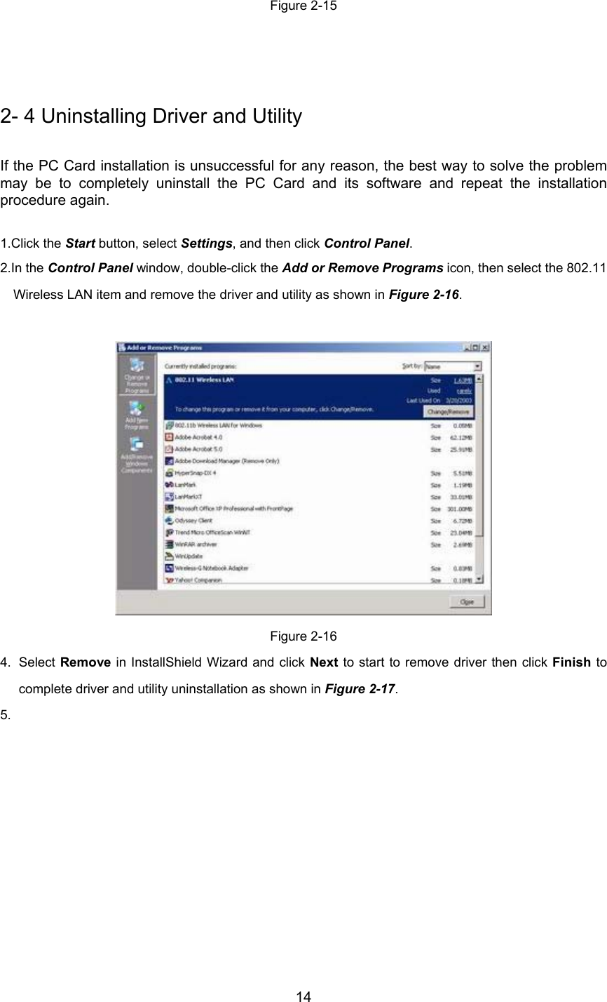
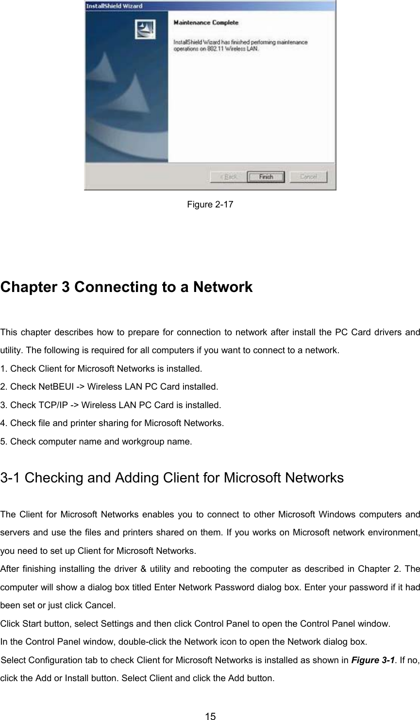
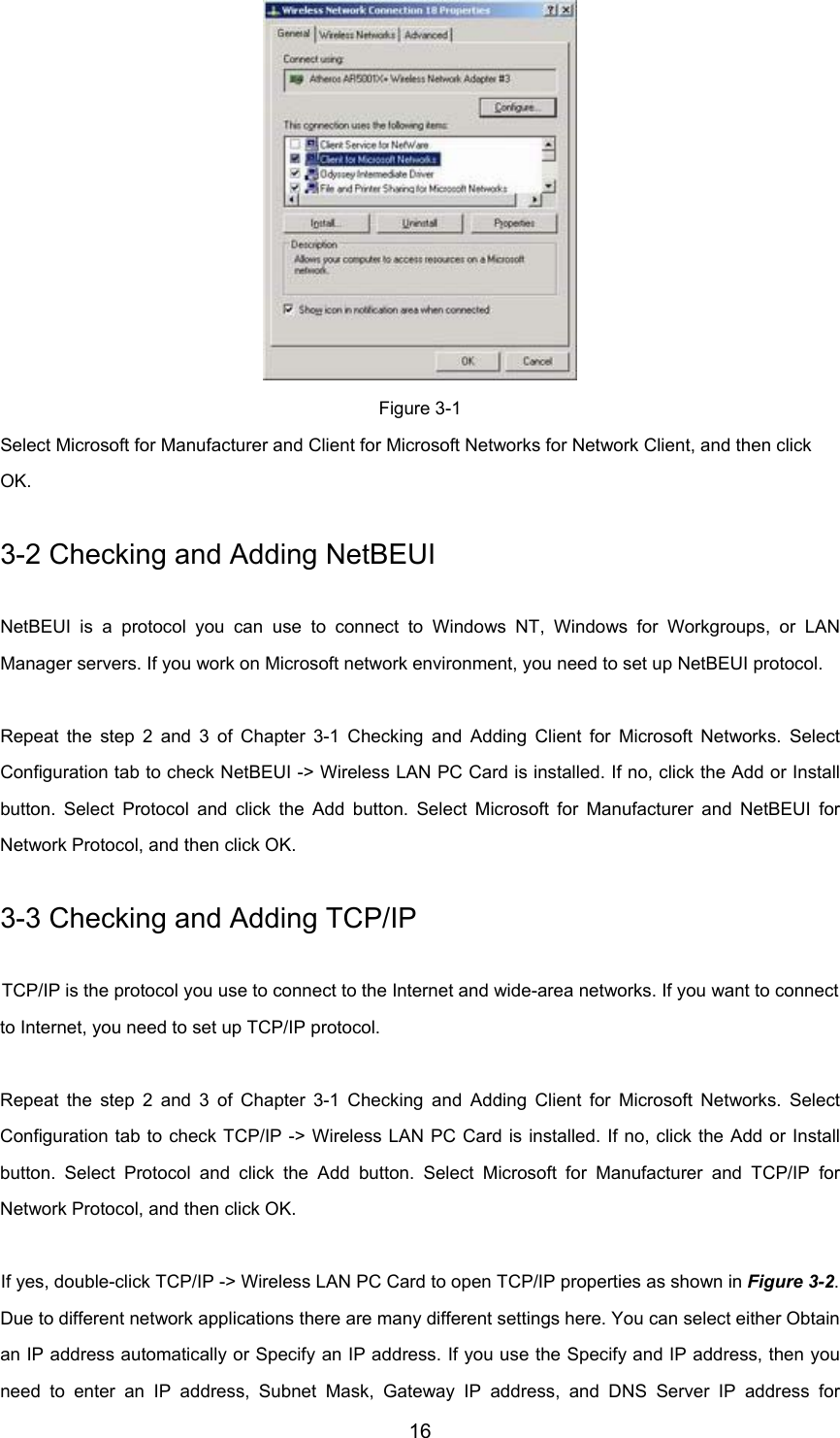
User Manual
Discussion / Help
Navigation