Senao Co OA35705001 Outdoor Access Point User Manual ZyBook
Senao International Co Ltd Outdoor Access Point ZyBook
UserManual.wiki
>
Senao Co
>
OA35705001 User Manual
>
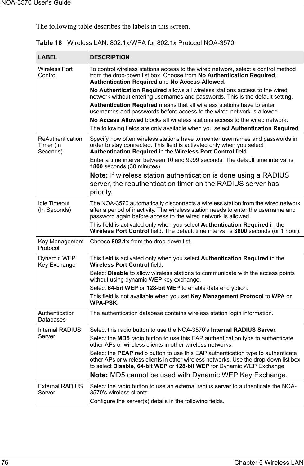
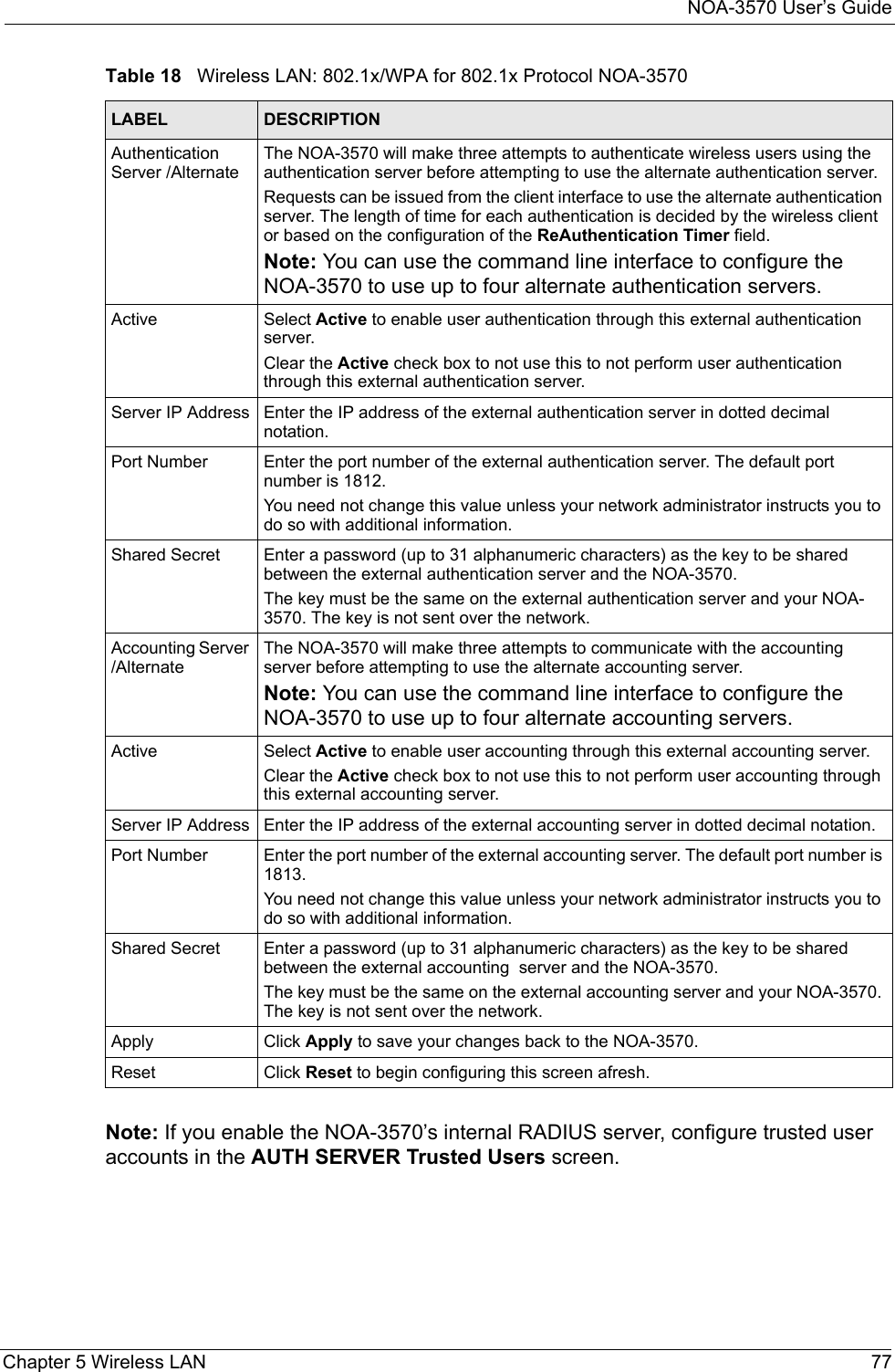
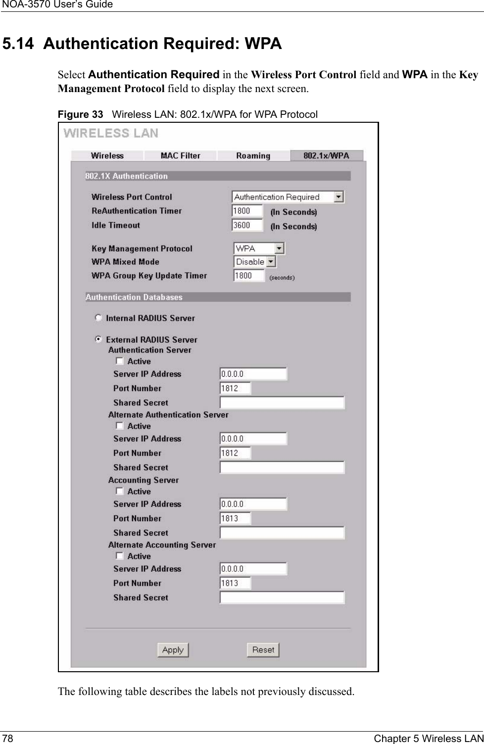
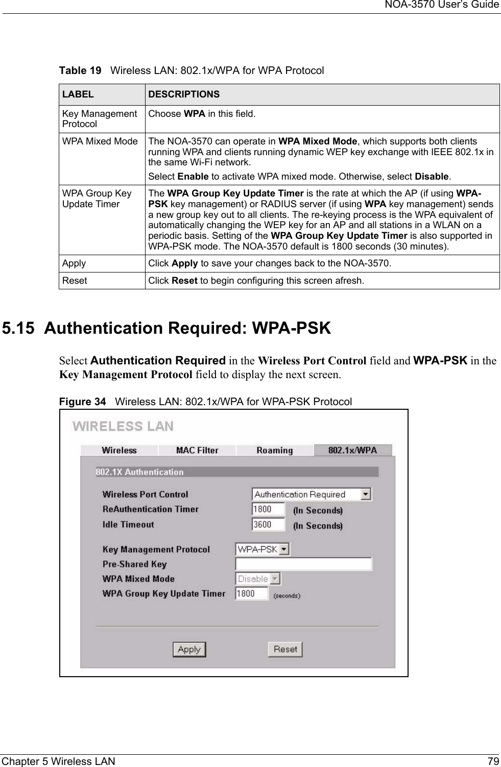
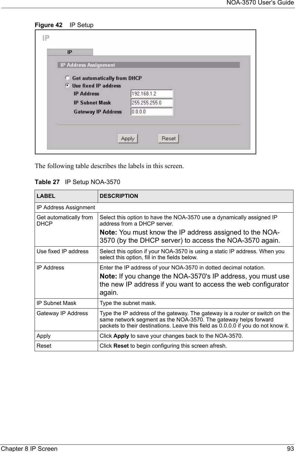
Manual Pt1
Contents
1.
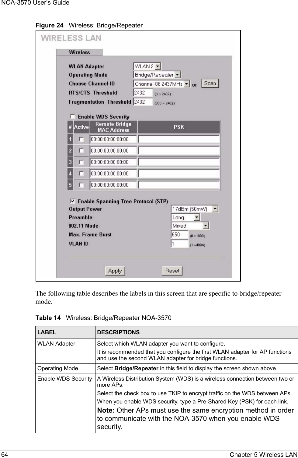
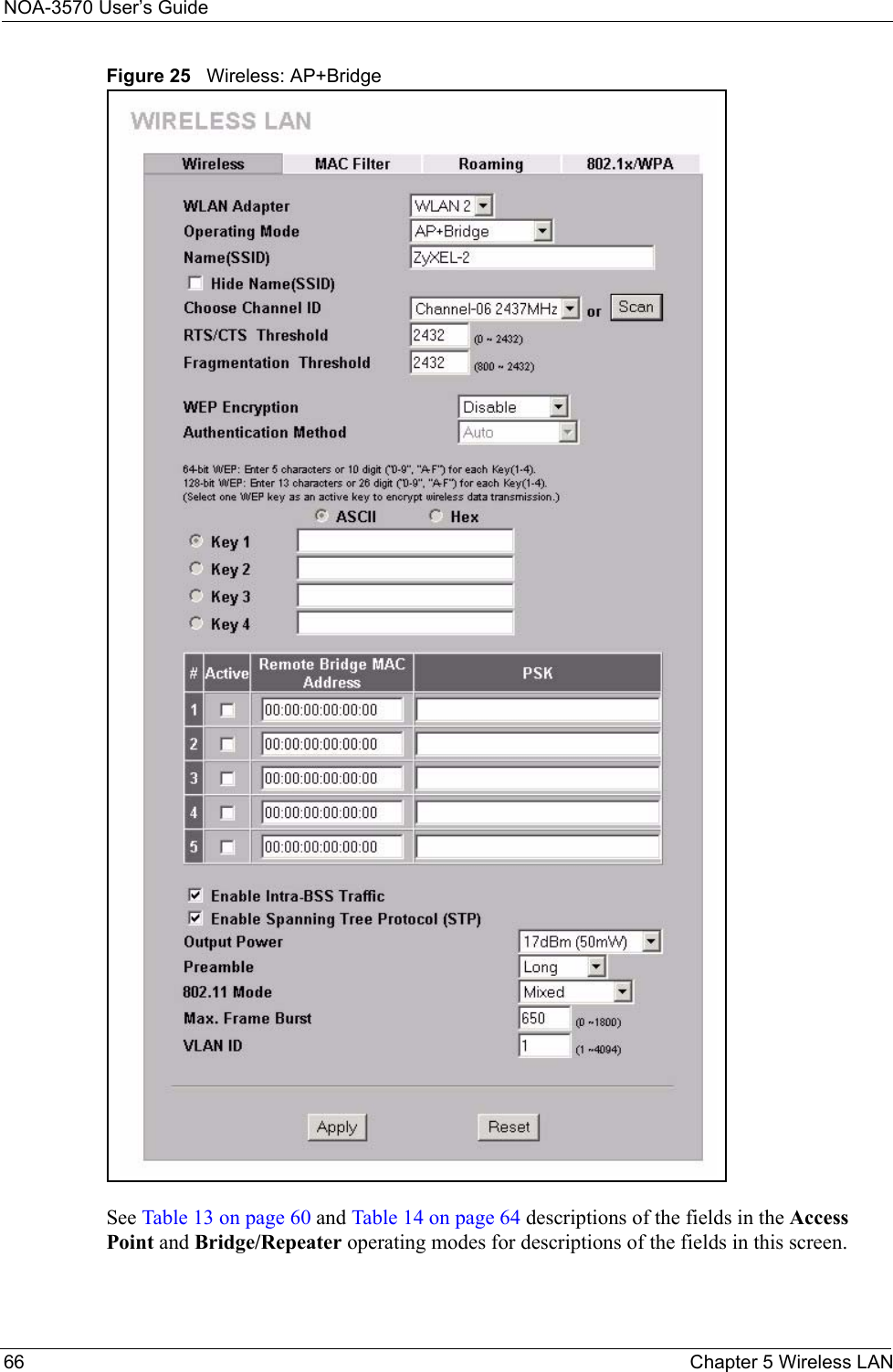
Manual Pt1
2.
Manual Pt2
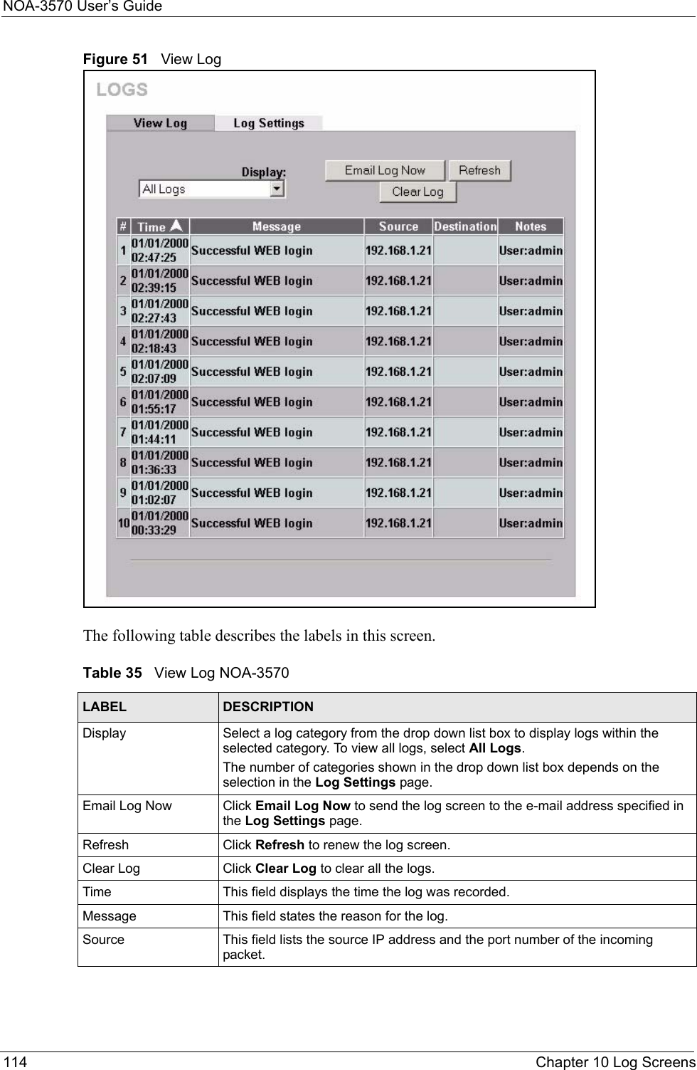
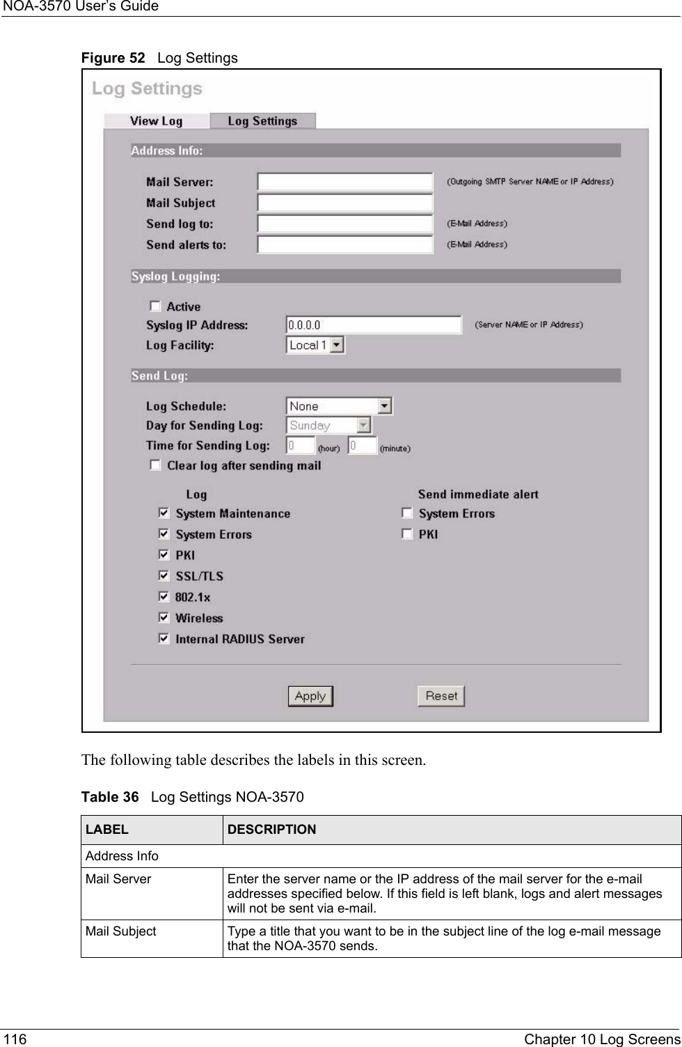
Manual Pt1
Navigation menu
Upload a User Manual
Namespaces
Wiki Guide
HTML
PDF
Info
Views
User Manual
Discussion / Help
Navigation