Senao Co OA35705001 Outdoor Access Point User Manual ZyBook
Senao International Co Ltd Outdoor Access Point ZyBook
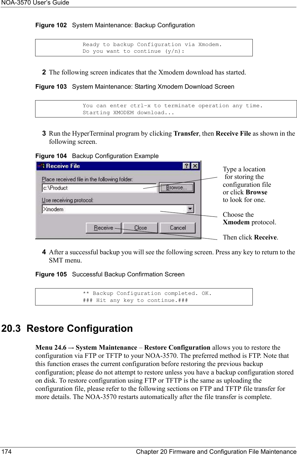
UserManual.wiki
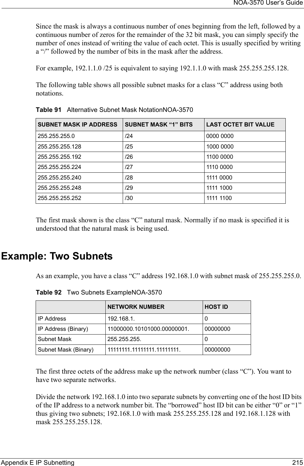
>
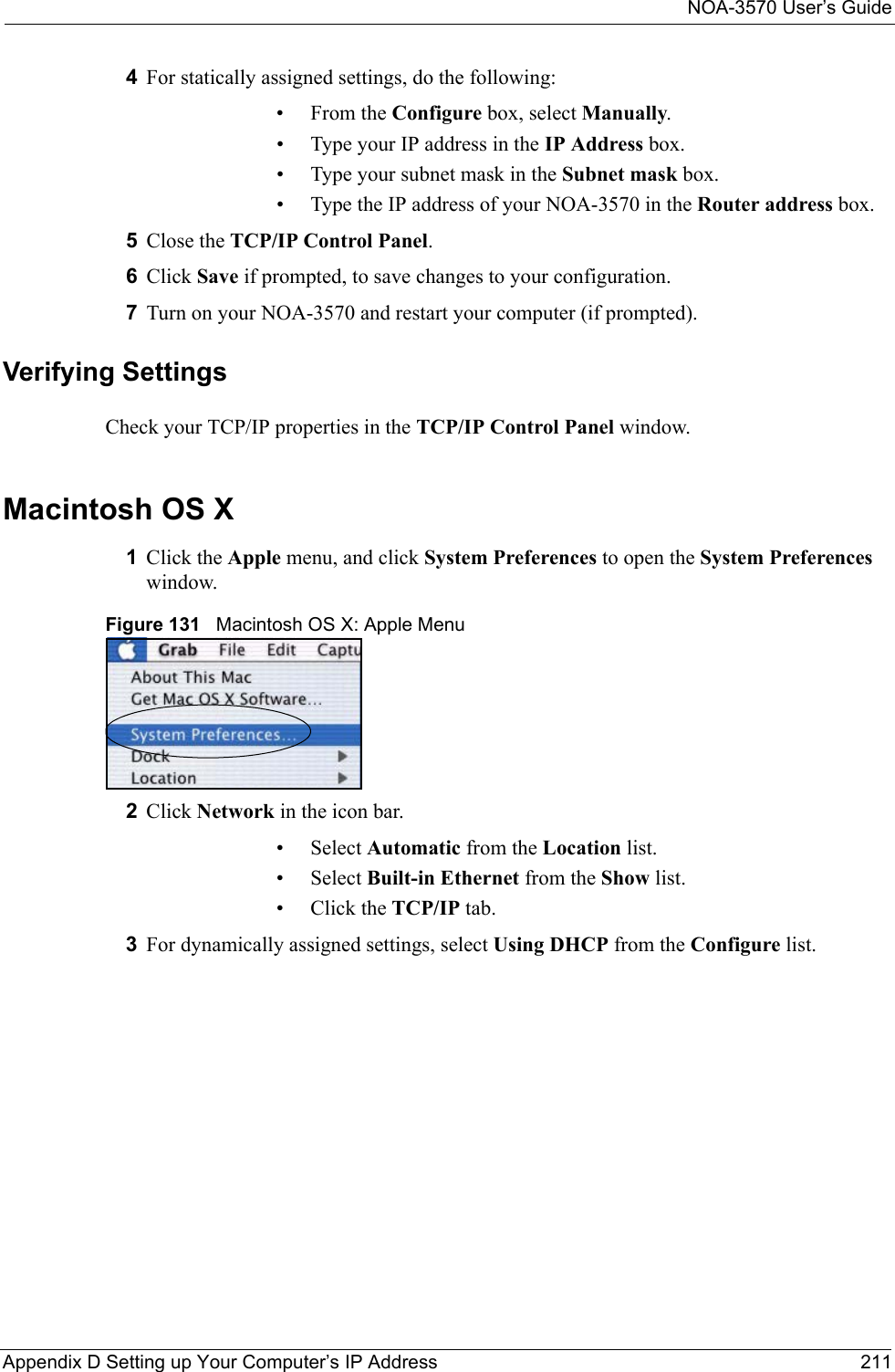
Senao Co
>
OA35705001 User Manual
>
Manual Pt2
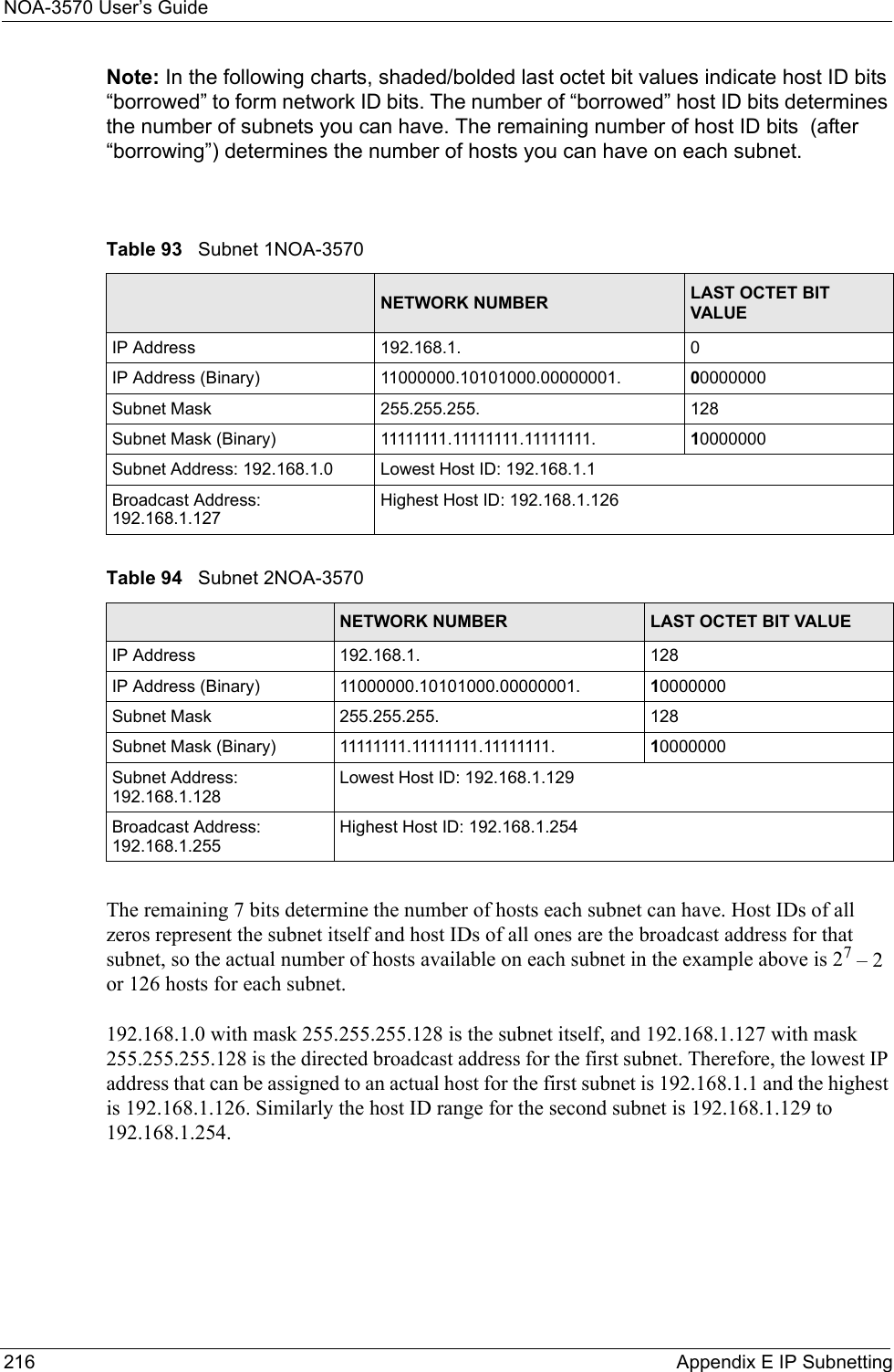
Contents
1.
Manual Pt1
2.
Manual Pt2
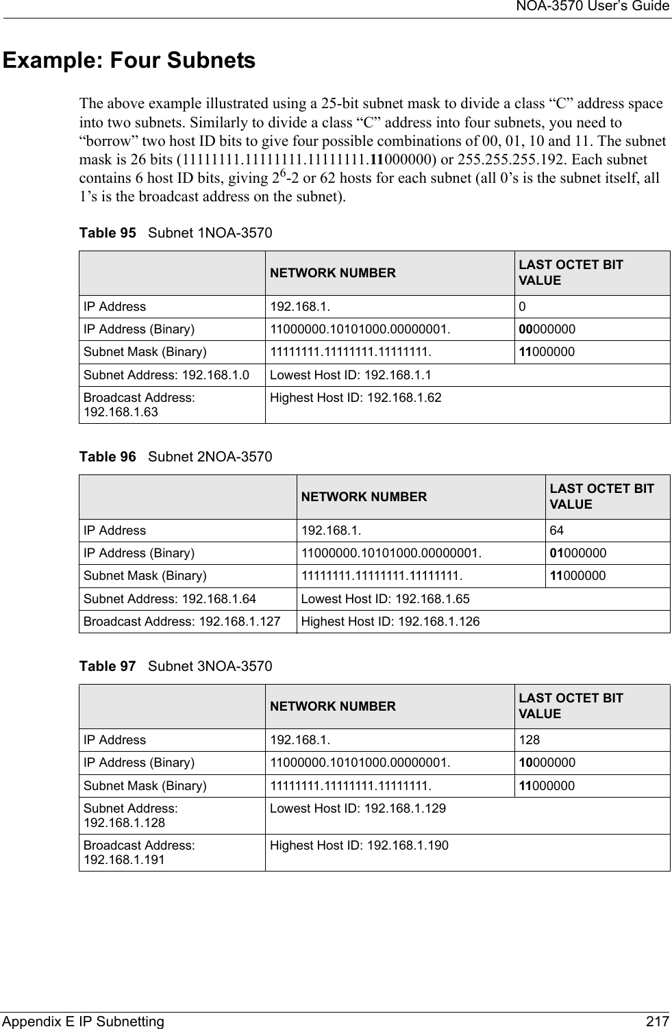
Manual Pt2
Navigation menu
Upload a User Manual
Namespaces
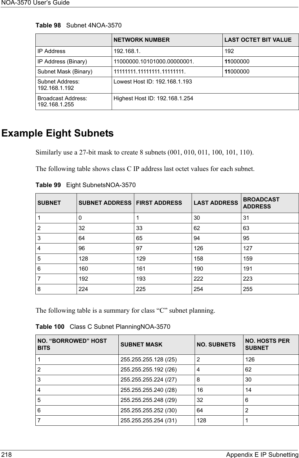
Wiki Guide
HTML
PDF
Info
Views
User Manual
Discussion / Help
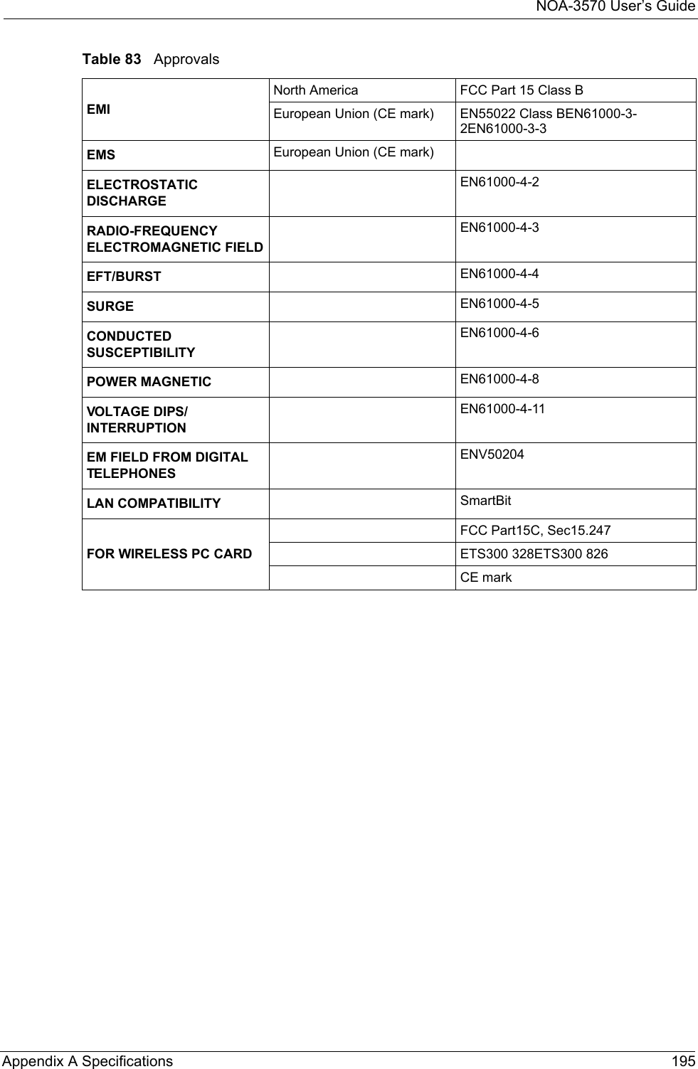
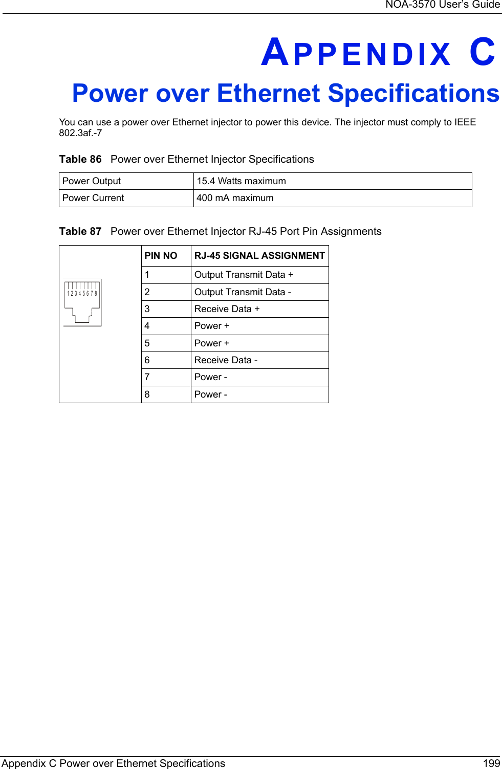
Navigation
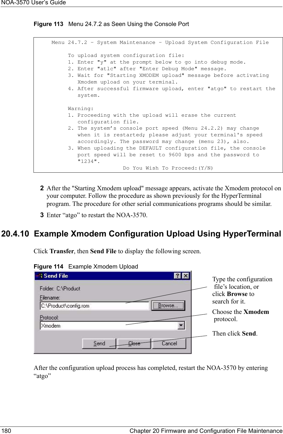
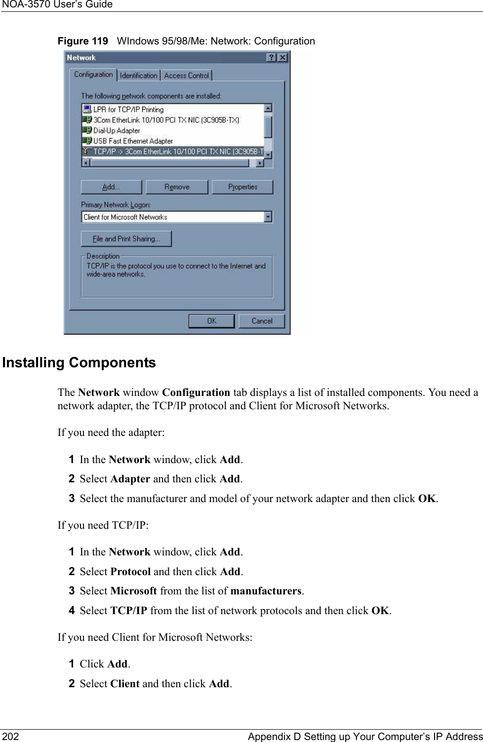
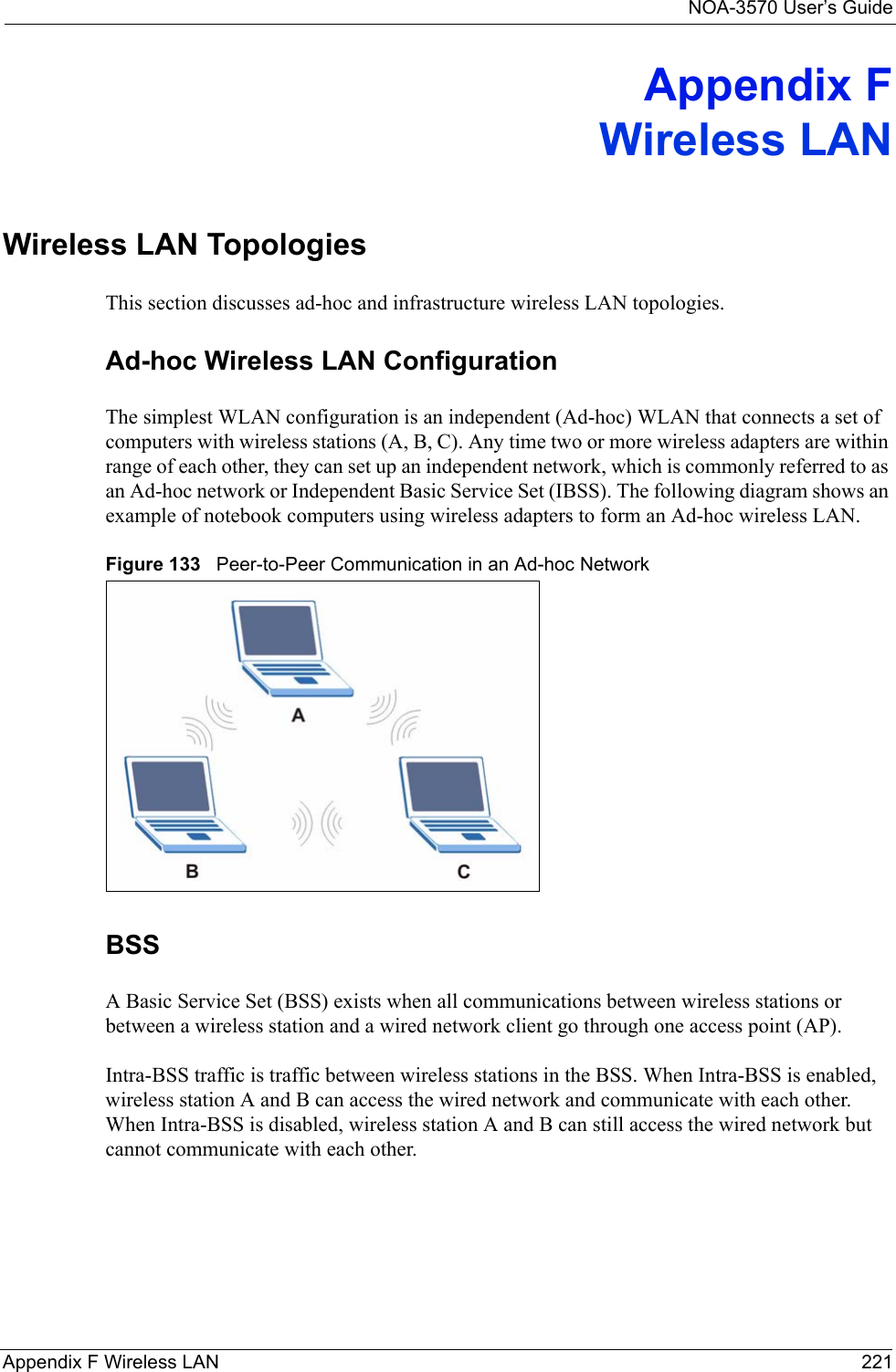
![NOA-3570 User’s GuideChapter 12 Introducing the SMT 131CHAPTER 12Introducing the SMTThis chapter describes how to access the SMT and provides an overview of its menus.12.1 Introduction to the SMTThe NOA-3570’s SMT (System Management Terminal) is a menu-driven interface that you can access from a terminal emulator through the console port or over a telnet connection. This chapter shows you how to access the SMT (System Management Terminal) menus, how to navigate the SMT and how to configure SMT menus.12.2 Accessing the SMT via the Console PortMake sure you have the physical connection properly set up as described in the Quick Start Guide. When configuring using the console port, you need a computer equipped with communications software configured to the following parameters:• VT100 terminal emulation.• 9600 Baud.• No parity, 8 data bits, 1 stop bit, flow control set to none.12.2.1 Initial ScreenWhen you turn on your NOA-3570, it performs several internal tests. After the tests, the NOA-3570 asks you to press [ENTER] to continue, as shown next.](https://usermanual.wiki/Senao-Co/OA35705001.Manual-Pt2/User-Guide-620617-Page-1.png)
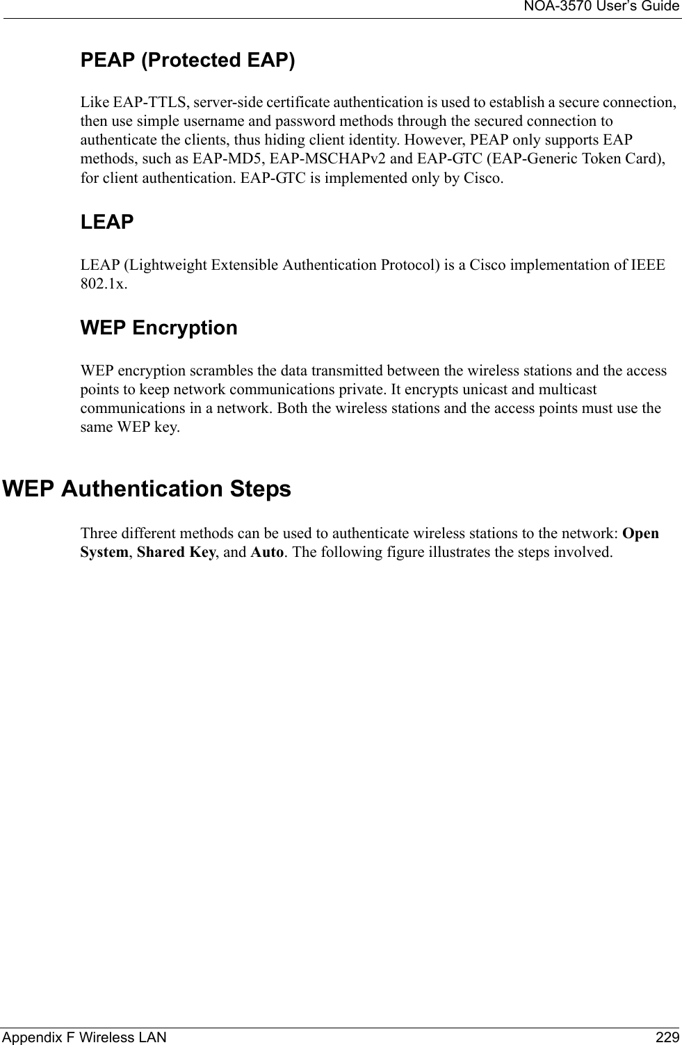
![NOA-3570 User’s Guide132 Chapter 12 Introducing the SMTFigure 67 Initial Screen12.2.2 Entering the PasswordThe login screen appears after you press [ENTER], prompting you to enter the password, as shown below.For your first login, enter the default password “1234”. As you type the password, the screen displays an “X” for each character you type.Please note that if there is no activity for longer than five minutes after you log in, your NOA-3570 will automatically log you out and display a blank screen. If you see a blank screen, press [ENTER] to bring up the login screen again.Figure 68 Password Screen Bootbase Version: V1.03 | 08/30/2004 16:28:56RAM:Size = 64 MbytesFLASH: Intel 128MZyNOS Version: V3.50(HV.0)b4 | 01/21/2005 14:25:43Press any key to enter debug mode within 3 seconds............................................................. (Compressed) Version: NOA-3570, start: 5012c030 Length: 46312C, Checksum: 4F98 Compressed Length: 161B28, Checksum: ED83Copyright (c) 1994 - 2005 ZyXEL Communications Corp.initialize ch =0, ethernet address: 00:A0:C5:62:B0:DBinitialize ch =1, ethernet address: 00:A0:C5:62:B0:DBinitialize ch =2, ethernet address: 00:A0:C5:62:B0:DCinitialize ch =3, ethernet address: 00:A0:C5:62:B0:DBinitialize ch =4, ethernet address: 00:A0:C5:62:B0:DBinitialize ch =5, ethernet address: 00:A0:C5:62:B0:DBinitialize ch =6, ethernet address: 00:A0:C5:62:B0:DBinitialize ch =7, ethernet address: 00:A0:C5:62:B0:DBinitialize ch =8, ethernet address: 00:A0:C5:62:B0:DCinitialize ch =9, ethernet address: 00:A0:C5:62:B0:DCinitialize ch =10, ethernet address: 00:A0:C5:62:B0:DCinitialize ch =11, ethernet address: 00:A0:C5:62:B0:DCinitialize ch =12, ethernet address: 00:A0:C5:62:B0:DCPress ENTER to continue...Enter Password : XXXX](https://usermanual.wiki/Senao-Co/OA35705001.Manual-Pt2/User-Guide-620617-Page-2.png)
![NOA-3570 User’s GuideChapter 12 Introducing the SMT 13312.3 Accessing the SMT via TelnetThe following procedure details how to telnet into your NOA-3570.1In Windows, click Start (usually in the bottom left corner), Run and then type “telnet 192.168.1.2” (the default IP address) and click OK. 2For your first login, enter the default password “1234”. As you type the password, the screen displays an asterisk “*” for each character you type.Figure 69 Login Screen3After entering the password you will see the main menu.Please note that if there is no activity for longer than five minutes (default timeout period) after you log in, your NOA-3570 will automatically log you out. You will then have to telnet into the NOA-3570 again. You can use the web configurator or the CI commands to change the inactivity time out period. 12.4 Navigating the SMT InterfaceThe SMT (System Management Terminal) is the interface that you use to configure your NOA-3570. Several operations that you should be familiar with before you attempt to modify the configuration are listed in the table below.Password : xxxxTable 43 Main Menu Commands NOA-3570OPERATION KEYSTROKE DESCRIPTIONMove down to another menu[ENTER] To move forward to a submenu, type in the number of the desired submenu and press [ENTER].Move up to a previous menu[ESC] Press [ESC] to move back to the previous menu.Move to a “hidden” menuPress [SPACE BAR] to change No to Yes then press [ENTER].Fields beginning with “Edit” lead to hidden menus and have a default setting of No. Press [SPACE BAR] once to change No to Yes, then press [ENTER] to go to the “hidden” menu.Move the cursor [ENTER] or [UP]/[DOWN] arrow keys.Within a menu, press [ENTER] to move to the next field. You can also use the [UP]/[DOWN] arrow keys to move to the previous and the next field, respectively.When you are at the top of a menu, press the [UP] arrow key to move to the bottom of a menu.Entering information Type in or press [SPACE BAR], then press [ENTER].You need to fill in two types of fields. The first requires you to type in the appropriate information. The second allows you to cycle through the available choices by pressing [SPACE BAR].](https://usermanual.wiki/Senao-Co/OA35705001.Manual-Pt2/User-Guide-620617-Page-3.png)
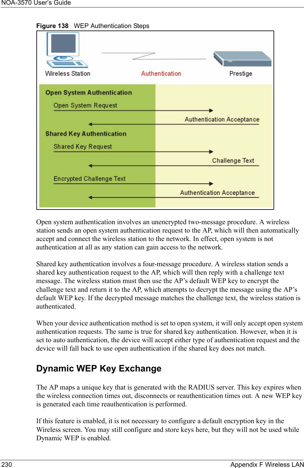
![NOA-3570 User’s Guide134 Chapter 12 Introducing the SMTAfter you enter the password, the SMT displays the main menu, as shown next.Figure 70 SMT Main Menu12.4.1 System Management Terminal Interface SummaryRequired fields <?> or ChangeMe All fields with the symbol <?> must be filled in order to be able to save the new configuration.All fields with ChangeMe must not be left blank in order to be able to save the new configuration.N/A fields <N/A> Some of the fields in the SMT will show a <N/A>. This symbol refers to an option that is Not Applicable.Save your configuration[ENTER] Save your configuration by pressing [ENTER] at the message “Press ENTER to confirm or ESC to cancel”. Saving the data on the screen will take you, in most cases to the previous menu.Make sure you save your settings in each screen that you configure.Exit the SMT Type 99, then press [ENTER].Type 99 at the main menu prompt and press [ENTER] to exit the SMT interface. Copyright (c) 1994 - 2005 ZyXEL Communications Corp. NOA-3570 Main Menu Getting Started Advanced Management 1. General Setup 22. SNMP Configuration 3. LAN Setup 23. System Security 24. System MaintenanceAdvanced Applications14. Dial-in User Setup16. VLAN Setup 99. Exit Enter Menu Selection Number:Table 43 Main Menu Commands NOA-3570OPERATION KEYSTROKE DESCRIPTIONTable 44 Main Menu Summary NOA-3570#MENU TITLE DESCRIPTION1General Setup Use this menu to set up your general information.3LAN Setup Use this menu to set up your LAN and WLAN connection.14 Dial-in User Setup Use this menu to set up local user profiles on the NOA-3570. 16 VLAN Setup Use this menu to set up your VLAN ID.22 SNMP Configuration Use this menu to set up SNMP related parameters.](https://usermanual.wiki/Senao-Co/OA35705001.Manual-Pt2/User-Guide-620617-Page-4.png)
![NOA-3570 User’s Guide136 Chapter 12 Introducing the SMT12.5 Changing the System PasswordChange the NOA-3570 default password by following the steps shown next. 1From the main menu, enter 23 to display Menu 23 – System Security.2Enter 1 to display Menu 23.1 – System Security – Change Password as shown next.3Type your existing system password in the Old Password field, and press [ENTER].Figure 71 Menu 23.1 System Security: Change Password 4Type your new system password in the New Password field (up to 30 characters), and press [ENTER].5Re-type your new system password in the Retype to confirm field for confirmation and press [ENTER].Note that as you type a password, the screen displays an asterisk “*” for each character you type.Menu 23.1 – System Security – Change Password Old Password= **** New Password= ? Retype to confirm= ? Enter here to CONFIRM or ESC to CANCEL:](https://usermanual.wiki/Senao-Co/OA35705001.Manual-Pt2/User-Guide-620617-Page-6.png)
![NOA-3570 User’s Guide138 Chapter 13 General SetupFill in the required fields. Refer to the following table for more information about these fields.Table 46 Menu 1 General SetupFIELD DESCRIPTIONSystem Name Choose a descriptive name for identification purposes. This name can be up to 30 alphanumeric characters long. Spaces are not allowed, but dashes “-” and underscores "_" are accepted. Domain Name This is not a required field. Leave this field blank or enter the domain name here if you know it.First/Second/Third System DNS ServerPress [SPACE BAR] to select From DHCP, User-Defined or None and press [ENTER].These fields are not available on all models.IP Address Enter the IP addresses of the DNS servers. This field is available when you select User-Defined in the field above.When you have completed this menu, press [ENTER] at the prompt “Press ENTER to Confirm…” to save your configuration, or press [ESC] at any time to cancel.](https://usermanual.wiki/Senao-Co/OA35705001.Manual-Pt2/User-Guide-620617-Page-8.png)
![NOA-3570 User’s GuideChapter 14 LAN Setup 139CHAPTER 14LAN SetupThis chapter shows you how to configure the LAN on your NOA-3570.14.1 LAN SetupThis section describes how to configure the Ethernet using Menu 3 – LAN Setup. From the main menu, enter 3 to display menu 3.Figure 73 Menu 3 LAN Setup 14.2 TCP/IP Ethernet SetupUse menu 3.2 to configure your NOA-3570 for TCP/IP.To edit menu 3.2, enter 3 from the main menu to display Menu 3-LAN Setup. When menu 3 appears, press 2 and press [ENTER] to display Menu 3.2-TCP/IP Setup, as shown next: Menu 3 - LAN Setup 2. TCP/IP Setup 5. Wireless LAN Setup Enter Menu Selection Number:](https://usermanual.wiki/Senao-Co/OA35705001.Manual-Pt2/User-Guide-620617-Page-9.png)
![NOA-3570 User’s Guide140 Chapter 14 LAN SetupFigure 74 Menu 3.2 TCP/IP SetupFollow the instructions in the following table on how to configure the fields in this menu.14.3 Wireless LAN SetupUse menu 3.5 to set up your NOA-3570 as the wireless access point. To edit menu 3.5, enter 3 from the main menu to display Menu 3 – LAN Setup. When menu 3 appears, press 5 and then press [ENTER] to display Menu 3.5 – Wireless LAN Setup as shown next. Menu 3.2 - TCP/IP Setup IP Address Assignment= Static IP Address= 192.168.1.2 IP Subnet Mask= 255.255.255.0 Gateway IP Address= 0.0.0.0Table 47 Menu 3.2 TCP/IP Setup NOA-3570FIELD DESCRIPTIONIP Address AssignmentPress [SPACE BAR] and then [ENTER] to select Dynamic to have the NOA-3570 obtain an IP address from a DHCP server. You must know the IP address assigned to the NOA-3570 (by the DHCP server) to access the NOA-3570 again. Select Static to give the NOA-3570 a fixed, unique IP address. Enter a subnet mask appropriate to your network and the gateway IP address if applicable.IP Address Enter the (LAN) IP address of your NOA-3570 in dotted decimal notationIP Subnet Mask Your NOA-3570 will automatically calculate the subnet mask based on the IP address that you assign. Unless you are implementing subnetting, use the subnet mask computed by the NOA-3570.Gateway IP AddressType the IP address of the gateway. The gateway is an immediate neighbor of your NOA-3570 that will forward the packet to the destination. On the LAN, the gateway must be a router on the same network segment as your NOA-3570.When you have completed this menu, press [ENTER] at the prompt “Press ENTER to Confirm…” to save your configuration, or press [ESC] at any time to cancel.](https://usermanual.wiki/Senao-Co/OA35705001.Manual-Pt2/User-Guide-620617-Page-10.png)
![NOA-3570 User’s GuideChapter 14 LAN Setup 141Figure 75 Menu 3.5 Wireless LAN SetupThe following table describes the fields in this menu. Menu 3.5 - Wireless LAN Setup WLAN Adapter= WLAN 1 Operating Mode= Access Point Name (SSID)= ZyXEL Hide Name (SSID)= No Edit MAC Address Filter= No Channel ID= CH06 2437MHz Edit Roaming Configuration= No RTS Threshold= 2432 Edit Bridge Link Configuration= N/A Frag. Threshold= 2432 Preamble= Long WEP Encryption= Disable 802.11 Mode= Mixed Default Key= N/A Max. Frame Burst= 650 Key1= N/A VLAN ID= 1 Key2= N/A Block Intra-BSS Traffic= No Key3= N/A Output Power= 21dBm Key4= N/A Authen. Method= N/A Press ENTER to Confirm or ESC to Cancel:Table 48 Menu 3.5 Wireless LAN Setup NOA-3570FIELD DESCRIPTIONWLAN Adapter Index Press [SPACE BAR] and select a wireless LAN adapter to configure. Operating Mode Press [SPACE BAR] and select Access Point, Multiple ESS, Bridge / Repeater or AP + Bridge.Name (SSID) The SSID (Service Set IDentity) identifies the AP to which the wireless stations associate. Wireless stations associating to the AP must have the same ESSID. Enter a descriptive name of up to 32 printable 7-bit ASCII characters.This field is only available when you select Access Point or AP + Bridge in the Operating Mode field.Hide Name (SSID) Press [SPACE BAR] and select Yes to hide the ESSID in the outgoing data frame so an intruder cannot obtain the ESSID through passive scanning. RTS Threshold Setting this attribute to zero turns on the RTS/CTS handshake. Enter a value between 0 and 2432.Frag. Threshold This is the maximum data fragment size that can be sent. Enter a value between 800 and 2432.WEP Encryption Select Disable to allow wireless stations to communicate with the access points without any data encryption. Select 64-bit WEP or 128-bit WEP to enable data encryption. Default Key Enter the key number (1 to 4) in this field. Only one key can be enabled at any one time. This key must be the same on the NOA-3570 and the wireless stations to communicate.](https://usermanual.wiki/Senao-Co/OA35705001.Manual-Pt2/User-Guide-620617-Page-11.png)
![NOA-3570 User’s Guide142 Chapter 14 LAN SetupKey 1 to Key 4 The WEP keys are used to encrypt data. Both the NOA-3570 and the wireless stations must use the same WEP key for data transmission.If you chose 64-bit WEP in the WEP Encryption field, then enter any 5 ASCII characters or 10 hexadecimal characters ("0-9", "A-F"). If you chose 128-bit WEP in the WEP Encryption field, then enter 13 ASCII characters or 26 hexadecimal characters ("0-9", "A-F").Note: Enter “0x” before the key to denote a hexadecimal key. Don’t enter “0x” before the key to denote an ASCII key.Authen. Method Press [SPACE BAR] to select Auto, Open System Only or Shared Key Only and press [ENTER]. This field is N/A if WEP is not activated. If WEP encryption is activated, the default setting is Auto. Edit MAC Address FilterPress [SPACE BAR] to select Yes and press [ENTER] to display Menu 3.5.1 - WLAN MAC Address Filter.Edit Roaming ConfigurationPress [SPACE BAR] to select Yes and press [ENTER] to display Menu 3.5.2 - Roaming Configuration.Edit Bridge Link ConfigurationUse [SPACE BAR] to choose Yes and press [ENTER] to go to Menu 3.5.4 - Bridge Link Configuration.Preamble Select a preamble type from the drop-down list menu. Choices are Long, Short and Dynamic. The default setting is Long.See the section on preamble for more information.802.11 Mode Select 802.11b Only to allow only IEEE 802.11b compliant WLAN devices to associate with the NOA-3570.Select 802.11g Only to allow only IEEE 802.11g compliant WLAN devices to associate with the NOA-3570.Select Mixed to allow either IEEE802.11b or IEEE802.11g compliant WLAN devices to associate with the NOA-3570. The transmission rate of your NOA-3570 might be reduced.Max. Frame Burst Enable Maximum Frame Burst to help eliminate collisions in mixed-mode networks (networks with both IEEE 802.11g and IEEE 802.11b traffic) and enhance the performance of both pure IEEE 802.11g and mixed IEEE 802.11b/g networks. Maximum Frame Burst sets the maximum time, in microseconds, that the NOA-3570 transmits IEEE 802.11g wireless traffic only. Type the maximum frame burst between 0 and 1800 (650, 1000 or 1800 recommended). Enter 0 to disable this feature.VLAN ID The NOA-3570 supports IEEE 802.1 tagged VLAN for partioning a physical network into multiple logical networks. Enter a number from 1 to 4094 to set the VLAN ID tag that the NOA-3570 adds to the Ethernet frames that this WLAN adapter receives from wireless clients or other APs. Block Intra-BSS TrafficPress [SPACE BAR] to select Yes to only allow wireless stations to communicate with the wired network, not with each other.Press [SPACE BAR] to select No to allow wireless stations connected to the NOA-3570 to communicate with each other. Output Power Level Press [SPACE BAR] to select the amount of power you want the NOA-3570 to use for the wireless signal. If there is a high density of APs within an area, decrease the output power of the NOA-3570 to reduce interference with other APs. The options are 21dBm, 19dBm, 17dBm or 15dBm.When you have completed this menu, press [ENTER] at the prompt “Press ENTER to confirm or ESC to cancel” to save your configuration or press [ESC] to cancel and go back to the previous screen.Table 48 Menu 3.5 Wireless LAN Setup NOA-3570FIELD DESCRIPTION](https://usermanual.wiki/Senao-Co/OA35705001.Manual-Pt2/User-Guide-620617-Page-12.png)
![NOA-3570 User’s GuideChapter 14 LAN Setup 14314.3.1 Configuring MAC Address FilterYour NOA-3570 checks the MAC address of the wireless station device against a list of allowed or denied MAC addresses. However, intruders could fake allowed MAC addresses so MAC-based authentication is less secure than EAP authentication. Follow the steps below to create the MAC address table on your NOA-3570.1From the main menu, enter 3 to open Menu 3 – LAN Setup.2Enter 5 to display Menu 3.5 – Wireless LAN Setup. Figure 76 Menu 3.5 Wireless LAN Setup3Press [SPACE BAR] to select Access Point or AP + Bridge in the Operating Mode field and press [ENTER].4In the Edit MAC Address Filter field, press [SPACE BAR] to select Yes and press [ENTER]. Menu 3.5.1 – WLAN MAC Address Filter displays as shown next. Menu 3.5 - Wireless LAN Setup Operating Mode= Access Point Name (SSID)= ZyXEL Hide Name (SSID)= No Edit MAC Address Filter= Yes Channel ID= CH06 2437MHz Edit Roaming Configuration= No RTS Threshold= 2432 Edit Bridge Link Configuration= N/A Frag. Threshold= 2432 Preamble= Long WEP Encryption= Disable 802.11 Mode= Mixed Default Key= N/A Max. Frame Burst= 650 Key1= N/A Block Intra-BSS Traffic= No Key2= N/A Output Power Level= 4 Key3= N/A Key4= N/A Authen. Method= N/A Press ENTER to Confirm or ESC to Cancel:Press Space Bar to Toggle.](https://usermanual.wiki/Senao-Co/OA35705001.Manual-Pt2/User-Guide-620617-Page-13.png)
![NOA-3570 User’s Guide144 Chapter 14 LAN SetupFigure 77 Menu 3.5.1 WLAN MAC Address FilterThe following table describes the fields in this menu.14.3.2 Configuring RoamingFollow the steps below to configure roaming on your NOA-3570.1From the main menu, enter 3 to open Menu 3 – LAN Setup.2Enter 5 to display Menu 3.5 – Wireless LAN Setup. Menu 3.5.1 - WLAN MAC Address Filter Active= No Filter Action= Allowed Association------------------------------------------------------------------------------ 1= 00:00:00:00:00:00 13= 00:00:00:00:00:00 25= 00:00:00:00:00:00 2= 00:00:00:00:00:00 14= 00:00:00:00:00:00 26= 00:00:00:00:00:00 3= 00:00:00:00:00:00 15= 00:00:00:00:00:00 27= 00:00:00:00:00:00 4= 00:00:00:00:00:00 16= 00:00:00:00:00:00 28= 00:00:00:00:00:00 5= 00:00:00:00:00:00 17= 00:00:00:00:00:00 29= 00:00:00:00:00:00 6= 00:00:00:00:00:00 18= 00:00:00:00:00:00 30= 00:00:00:00:00:00 7= 00:00:00:00:00:00 19= 00:00:00:00:00:00 31= 00:00:00:00:00:00 8= 00:00:00:00:00:00 20= 00:00:00:00:00:00 32= 00:00:00:00:00:00 9= 00:00:00:00:00:00 21= 00:00:00:00:00:00 10= 00:00:00:00:00:00 22= 00:00:00:00:00:00 11= 00:00:00:00:00:00 23= 00:00:00:00:00:00 12= 00:00:00:00:00:00 24= 00:00:00:00:00:00------------------------------------------------------------------------------ Enter here to CONFIRM or ESC to CANCEL:Table 49 Menu 3.5.1 WLAN MAC Address Filter NOA-3570FIELD DESCRIPTIONActive To enable MAC address filtering, press [SPACE BAR] to select Yes and press [ENTER]. Filter Action Define the filter action for the list of MAC addresses in the MAC address filter table. To deny access to the NOA-3570, press [SPACE BAR] to select Deny Association and press [ENTER]. MAC addresses not listed will be allowed to access the router.The default action, Allowed Association, permits association with the NOA-3570. MAC addresses not listed will be denied access to the router. MAC Address Filter1..32 Enter the MAC addresses (in XX:XX:XX:XX:XX:XX format) of the client computers that are allowed or denied access to the NOA-3570 in these address fields. When you have completed this menu, press [ENTER] at the prompt “Press ENTER to confirm or ESC to cancel” to save your configuration or press [ESC] to cancel and go back to the previous screen.](https://usermanual.wiki/Senao-Co/OA35705001.Manual-Pt2/User-Guide-620617-Page-14.png)
![NOA-3570 User’s GuideChapter 14 LAN Setup 145Figure 78 Menu 3.5 Wireless LAN Setup3In the Operating Mode field, press [SPACE BAR] to select AP or AP + Bridge and press [ENTER].4Move the cursor to the Edit Roaming Configuration field. Press [SPACE BAR] to select Yes and press [ENTER]. Menu 3.5.2 – Roaming Configuration displays as shown next.Figure 79 Menu 3.5.2 - Roaming ConfigurationThe following table describes the fields in this menu. Menu 3.5 - Wireless LAN Setup Operating Mode= Access Point Name (SSID)= ZyXEL Hide Name (SSID)= No Edit MAC Address Filter= No Channel ID= CH06 2437MHz Edit Roaming Configuration= No RTS Threshold= 2432 Edit Bridge Link Configuration= N/A Frag. Threshold= 2432 Preamble= Long WEP Encryption= Disable 802.11 Mode= Mixed Default Key= N/A Max. Frame Burst= 650 Key1= N/A Block Intra-BSS Traffic= No Key2= N/A Output Power Level= 4 Key3= N/A Key4= N/A Authen. Method= N/A Press ENTER to Confirm or ESC to Cancel: Menu 3.5.2 - Roaming Configuration Active= No Port #= N/A](https://usermanual.wiki/Senao-Co/OA35705001.Manual-Pt2/User-Guide-620617-Page-15.png)
![NOA-3570 User’s Guide146 Chapter 14 LAN Setup14.3.3 Configuring Bridge Link Follow the steps below to configure bridge link on your NOA-3570.1From the main menu, enter 3 to open Menu 3 – LAN Setup.2Enter 5 to display Menu 3.5 – Wireless LAN Setup. Figure 80 Menu 3.5 Wireless LAN Setup3In the Operating Mode field, press [SPACE BAR] to select Bridge / Repeater or AP + Bridge and press [ENTER].Table 50 Menu 3.5.2 - Roaming Configuration NOA-3570FIELD DESCRIPTIONActive Press [SPACE BAR] to select Yes from the drop-down list box to enable roaming on the NOA-3570 if you have two or more NOA-3570s on the same subnet.Note: All APs on the same subnet and the wireless stations must have the same SSID to allow roaming.Port Type the port number to communicate roaming information between access points. The port number must be the same on all access points. The default is 3517. Make sure this port is not used by other services. When you have completed this menu, press [ENTER] at the prompt “Press ENTER to confirm or ESC to cancel” to save your configuration or press [ESC] to cancel and go back to the previous screen. Menu 3.5 - Wireless LAN Setup Operating Mode= Bridge / Repeater Name (SSID)= N/A Hide Name (SSID)= N/A Edit MAC Address Filter= N/A Channel ID= CH06 2437MHz Edit Roaming Configuration= N/A RTS Threshold= 2432 Edit Bridge Link Configuration= Yes Frag. Threshold= 2432 Preamble= Long WEP Encryption= Disable 802.11 Mode= Mixed Default Key= N/A Max. Frame Burst= 650 Key1= N/A Block Intra-BSS Traffic= No Key2= N/A Output Power Level= 4 Key3= N/A Key4= N/A Authen. Method= N/A Press ENTER to Confirm or ESC to Cancel:Press Space Bar to Toggle.](https://usermanual.wiki/Senao-Co/OA35705001.Manual-Pt2/User-Guide-620617-Page-16.png)
![NOA-3570 User’s GuideChapter 14 LAN Setup 1474Move the cursor to the Edit Bridge Link Configuration field. Press [SPACE BAR] to select Yes and press [ENTER]. Menu 3.5.4 – Bridge Link Configuration displays as shown next.Figure 81 Menu 3.5.4 - Bridge Link ConfigurationThe following table describes the fields in this menu. Menu 3.5.4 - Bridge Link Configuration Enable Link 1= No Peer MAC Address= 00:00:00:00:00:00 PSK= N/A Enable Link 2= No Peer MAC Address= 00:00:00:00:00:00 PSK= N/A Enable Link 3= No Peer MAC Address= 00:00:00:00:00:00 PSK= N/A Enable Link 4= No Peer MAC Address= 00:00:00:00:00:00 PSK= N/A Enable Link 5= No Peer MAC Address= 00:00:00:00:00:00 PSK= N/A Enable WDS Security= No Press ENTER to Confirm or ESC to Cancel:Table 51 Menu 3.5.4 Bridge Link Configuration NOA-3570FIELD DESCRIPTIONEnable Link 1-6 Press [SPACE BAR] to select Yes or No and press [ENTER]. Peer MAC Address Type the MAC address of a wireless bridge in valid MAC address format, that is, six hexadecimal character pairs, for example, 12:34:56:78:9a:bc.Enable WDS Security A Wireless Distribution System (WDS) is a wireless connection between two or more APs.Press [SPACE BAR] to select Yes to use TKIP to encrypt traffic on the WDS between APs.When you enable WDS security, type a Pre-Shared Key (PSK) for each link. Note: Other wireless bridges must use the same encryption method to enable WDS security. PSK When you enable WDS, type a Pre-Shared Key (PSK) for each link. The pre-shared key can be from 8 to 63 case-sensitive ASCII characters (including spaces and symbols).When you have completed this menu, press [ENTER] at the prompt “Press ENTER to confirm or ESC to cancel” to save your configuration or press [ESC] to cancel and go back to the previous screen.](https://usermanual.wiki/Senao-Co/OA35705001.Manual-Pt2/User-Guide-620617-Page-17.png)
![NOA-3570 User’s GuideChapter 15 Dial-in User Setup 149CHAPTER 15Dial-in User SetupThis chapter shows you how to create user accounts on the NOA-3570. 15.1 Dial-in User SetupBy storing user profiles locally, your NOA-3570 is able to authenticate wireless users without interacting with a network RADIUS server. Follow the steps below to set up user profiles on your NOA-3570.From the main menu, enter 14 to display Menu 14 - Dial-in User Setup.Figure 82 Menu 14- Dial-in User SetupType a number and press [ENTER] to edit the user profile. Figure 83 Menu 14.1- Edit Dial-in UserThe following table describes the fields in this screen. Menu 14 - Dial-in User Setup1. ________ 9. ________ 17. ________ 25. ________2. ________ 10. ________ 18. ________ 26. ________3. ________ 11. ________ 19. ________ 27. ________4. ________ 12. ________ 20. ________ 28. ________5. ________ 13. ________ 21. ________ 29. ________6. ________ 14. ________ 22. ________ 30. ________7. ________ 15. ________ 23. ________ 31. ________8. ________ 16. ________ 24. ________ 32. ________ Enter Menu Selection Number:Menu 14.1 - Edit Dial-in UserUser Name= testActive= YesPassword= ********Press ENTER to Confirm or ESC to Cancel:Leave name field blank to delete profile](https://usermanual.wiki/Senao-Co/OA35705001.Manual-Pt2/User-Guide-620617-Page-19.png)
![NOA-3570 User’s Guide150 Chapter 15 Dial-in User SetupTable 52 Menu 14.1- Edit Dial-in User NOA-3570FIELD DESCRIPTIONUser Name Enter a username up to 31 alphanumeric characters long for this user profile.This field is case sensitive.Active Press [SPACE BAR] to select Yes and press [ENTER] to enable the user profile. Password Enter a password up to 31 characters long for this user profile. When you have completed this menu, press [ENTER] at the prompt “Press ENTER to confirm or ESC to cancel” to save your configuration or press [ESC] to cancel and go back to the previous screen.](https://usermanual.wiki/Senao-Co/OA35705001.Manual-Pt2/User-Guide-620617-Page-20.png)
![NOA-3570 User’s GuideChapter 16 VLAN Setup 151CHAPTER 16VLAN SetupThis chapter explains VLAN setup menu 16. Refer to the web configurator VLAN chapter for background information on VLAN.16.1 VLAN SetupTo setup VLAN, select option 16 from the main menu to open Menu 16 – VLAN Setup as shown next.Figure 84 Menu 16 VLAN SetupThe following table describes the fields in this menu. Menu 16 - VLAN Setup VLAN Tagging= Yes Native VLAN ID= 1Table 53 Menu 16 VLAN SetupFIELD DESCRIPTIONVLAN Tagging To enable VLAN tagging, press [SPACE BAR] to select Yes and press [ENTER].Native VLAN ID This field is activated only when you select Yes in the VLAN Tagging field.Enter a number from 1 to 4094 to specify the ID of the management VLAN. Your management computer must belong to this VLAN group in order to manage the NOA-3570. This can be done in the following ways:• The management computer could be a wireless client of the NOA-3570 if the NOA-3570’s WLAN adapter is set to add the add the management VLAN ID tag to Ethernet frames received from wireless clients.• The management computer could be on the wired network, behind a VLAN-aware switch that is configured to add the management VLAN ID tag to Ethernet frames from the computer before sending them to NOA-3570.Note: Mail and FTP servers must have the same management VLAN ID to communicate with the NOA-3570.When you have completed this menu, press [ENTER] at the prompt “Press ENTER to confirm or ESC to cancel” to save your configuration or press [ESC] to cancel and go back to the previous screen.](https://usermanual.wiki/Senao-Co/OA35705001.Manual-Pt2/User-Guide-620617-Page-21.png)

![NOA-3570 User’s GuideChapter 17 SNMP Configuration 15517.4 SNMP Traps The NOA-3570 will send traps to the SNMP manager when any one of the following events occurs:The following table maps the physical port and encapsulation to the interface type,Table 54 Menu 22 SNMP Configuration NOA-3570FIELD DESCRIPTIONSNMP:Get Community Type the Get Community, which is the password for the incoming Get- and GetNext requests from the management station.Set Community Type the Set Community, which is the password for incoming Set requests from the management station. Trusted Host If you enter a trusted host, your NOA-3570 will only respond to SNMP messages from this address. A blank (default) field means your NOA-3570 will respond to all SNMP messages it receives, regardless of source.Trap:Community Type the trap community, which is the password sent with each trap to the SNMP manager. Destination Type the IP address of the station to send your SNMP traps to.When you have completed this menu, press [ENTER] at the prompt “Press ENTER to confirm or ESC to cancel” to save your configuration or press [ESC] to cancel and go back to the previous screen.Table 55 SNMP Traps NOA-3570TRAP # TRAP NAME DESCRIPTION1coldStart (defined in RFC-1215)A trap is sent after booting (power on).2warmStart (defined in RFC-1215)A trap is sent after booting (software reboot).3linkUp (defined in RFC-1215)A trap is sent when the port is up.4authenticationFailure (defined in RFC-1215)A trap is sent to the manager when receiving any SNMP get or set requirements with wrong community (password).6linkDown (defined in RFC-1215)A trap is sent when the port is down.Table 56 Ports and Interface Types NOA-3570PHYSICAL PORT/ENCAP INTERFACE TYPEWLAN 1 enet0Ethernet port enet1 WLAN 2 enet2](https://usermanual.wiki/Senao-Co/OA35705001.Manual-Pt2/User-Guide-620617-Page-25.png)
![NOA-3570 User’s Guide158 Chapter 18 System SecurityFrom Menu 23- System Security, enter 2 to display Menu 23.2 – System Security – RADIUS Server as shown next.Figure 89 Menu 23.2 System Security: RADIUS ServerThe following table describes the fields in this menu. Menu 23.2 - System Security - RADIUS ServerAuthentication Server:Active= NoServer Address= 0.0.0.0Port #= 1812Shared Secret= ********Accounting Server:Active= NoServer Address= 0.0.0.0Port #= 1813Shared Secret= ********Press ENTER to Confirm or ESC to Cancel:Table 57 Menu 23.2 System Security: RADIUS Server NOA-3570FIELD DESCRIPTIONAuthentication ServerActive Press [SPACE BAR] to select Yes and press [ENTER] to enable user authentication through an external authentication server. Server Address To use an external authentication server, enter its IP address in dotted decimal notation. Enter 127.0.0.1 to use the internal authentication server.Port The default port of the RADIUS server for authentication is 1812. You need not change this value unless your network administrator instructs you to do so with additional information. Shared Secret To use an external authentication server, specify a password (up to 31 alphanumeric characters) as the key to be shared between the external authentication server and the access points. The key is not sent over the network. This key must be the same on the external authentication server and NOA-3570. Enter 1234 to use the internal authentication server.Accounting ServerActive Press [SPACE BAR] to select Yes and press [ENTER] to enable user authentication through an external accounting server. Server Address Enter the IP address of the external accounting server in dotted decimal notation. Port The default port of the RADIUS server for accounting is 1813. You need not change this value unless your network administrator instructs you to do so with additional information.](https://usermanual.wiki/Senao-Co/OA35705001.Manual-Pt2/User-Guide-620617-Page-28.png)
![NOA-3570 User’s GuideChapter 18 System Security 15918.1.3 802.1x The IEEE 802.1x standards outline enhanced security methods for both the authentication of wireless stations and encryption key management.Follow the steps below to enable EAP authentication on your NOA-3570. 1From the main menu, enter 23 to display Menu23 – System Security.Figure 90 Menu 23 System Security2Enter 4 to display Menu 23.4 – System Security – IEEE802.1x.Shared Secret Specify a password (up to 31 alphanumeric characters) as the key to be shared between the external accounting server and the access points. The key is not sent over the network. This key must be the same on the external accounting server and NOA-3570.When you have completed this menu, press [ENTER] at the prompt “Press ENTER to confirm or ESC to cancel” to save your configuration or press [ESC] to cancel and go back to the previous screen.Table 57 Menu 23.2 System Security: RADIUS Server NOA-3570FIELD DESCRIPTION Menu 23 - System Security1. Change Password2. RADIUS Server4. IEEE802.1xEnter Menu Selection Number:](https://usermanual.wiki/Senao-Co/OA35705001.Manual-Pt2/User-Guide-620617-Page-29.png)
![NOA-3570 User’s Guide160 Chapter 18 System SecurityFigure 91 Menu 23.4 System Security: IEEE802.1xThe following table describes the fields in this menu.Menu 23.4 - System Security - IEEE802.1x Wireless Port Control= Authentication Required ReAuthentication Timer (in second)= 1800 Idle Timeout (in second)= 3600 Key Management Protocol= 802.1x Dynamic WEP Key Exchange= 128-bit WEP PSK= N/A WPA Mixed Mode= N/A WPA Group Key Update Timer= N/A Authentication Databases= Local User Database Only Press ENTER to Confirm or ESC to Cancel:Press Space Bar to Toggle.Table 58 Menu 23.4 System Security: IEEE802.1x NOA-3570FIELD DESCRIPTIONWireless Port Control Press [SPACE BAR] and select a security mode for the wireless LAN access. Select No Authentication Required to allow any wireless stations access to your wired network without entering usernames and passwords. This is the default setting.Selecting Authentication Required means wireless stations have to enter usernames and passwords before access to the wired network is allowed. Select No Access Allowed to block all wireless stations access to the wired network. The following fields are not available when you select No Authentication Required or No Access Allowed.ReAuthentication Timer (in second)Specify how often a client has to re-enter username and password to stay connected to the wired network. This field is activated only when you select Authentication Required in the Wireless Port Control field. Enter a time interval between 10 and 9999 (in seconds). The default time interval is 1800 seconds (or 30 minutes). Idle Timeout (in second)The NOA-3570 automatically disconnects a client from the wired network after a period of inactivity. The client needs to enter the username and password again before access to the wired network is allowed. This field is activated only when you select Authentication Required in the Wireless Port Control field. The default time interval is 3600 seconds (or 1 hour).Key Management ProtocolPress [SPACE BAR] to select 802.1x, WPA or WPA-PSK and press [ENTER].](https://usermanual.wiki/Senao-Co/OA35705001.Manual-Pt2/User-Guide-620617-Page-30.png)
![NOA-3570 User’s GuideChapter 18 System Security 161Once you enable user authentication, you need to specify an external RADIUS server or create local user accounts on the NOA-3570 for authenticationDynamic WEP Key ExchangeThis field is activated only when you select Authentication Required in the Wireless Port Control field. Also set the Authentication Databases field to RADIUS Only. Local user database may not be used. Select Disable to allow wireless stations to communicate with the access points without using Dynamic WEP Key Exchange. Select 64-bit WEP or 128-bit WEP to enable data encryption. Up to 32 stations can access the NOA-3570 when you configure Dynamic WEP Key Exchange.PSK Type a pre-shared key from 8 to 63 case-sensitive ASCII characters (including spaces and symbols) when you select WPA-PSK in the Key Management Protocol field. WPA Mixed Mode Select Enable to activate WPA mixed mode. Otherwise, select Disable and configure Data Privacy for Broadcast/Multicast packets field.WPA Group Key Update TimerThe WPA Broadcast/Multicast Key Update Timer is the rate at which the AP (if using WPA-PSK key management) or RADIUS server (if using WPA key management) sends a new group key out to all clients. The re-keying process is the WPA equivalent of automatically changing the WEP key for an AP and all stations in a WLAN on a periodic basis. Setting of the WPA Broadcast/Multicast Key Update Timer is also supported in WPA-PSK mode. The NOA-3570 default is 1800 seconds (30 minutes).Authentication DatabasesThe authentication database contains wireless station login information. The local user database is the built-in database on the NOA-3570. The RADIUS is an external server. Use this field to decide which database the NOA-3570 should use (first) to authenticate a wireless station.Before you specify the priority, make sure you have set up the corresponding database correctly first. When you configure Key Management Protocol to WPA, the Authentication Databases must be RADIUS Only. You can only use the Local User Database with 802.1x Key Management Protocol.Select Local User Database Only to have the NOA-3570 just check the built-in user database on the NOA-3570 for a wireless station's username and password. Select RADIUS Only to have the NOA-3570 just check the user database on the external RADIUS server for a wireless station's username and password. Select Local first, then RADIUS to have the NOA-3570 first check the user database on the NOA-3570 for a wireless station's username and password. If the user name is not found, the NOA-3570 then checks the user database on the external RADIUS server.Select RADIUS first, then Local to have the NOA-3570 first check the user database on the external RADIUS server for a wireless station's username and password. If the NOA-3570 cannot reach the RADIUS server, the NOA-3570 then checks the local user database on the NOA-3570. When the user name is not found or password does not match in the RADIUS server, the NOA-3570 will not check the local user database and the authentication fails.When you have completed this menu, press [ENTER] at the prompt “Press ENTER to confirm or ESC to cancel” to save your configuration or press [ESC] to cancel and go back to the previous screen.Table 58 Menu 23.4 System Security: IEEE802.1x NOA-3570FIELD DESCRIPTION](https://usermanual.wiki/Senao-Co/OA35705001.Manual-Pt2/User-Guide-620617-Page-31.png)

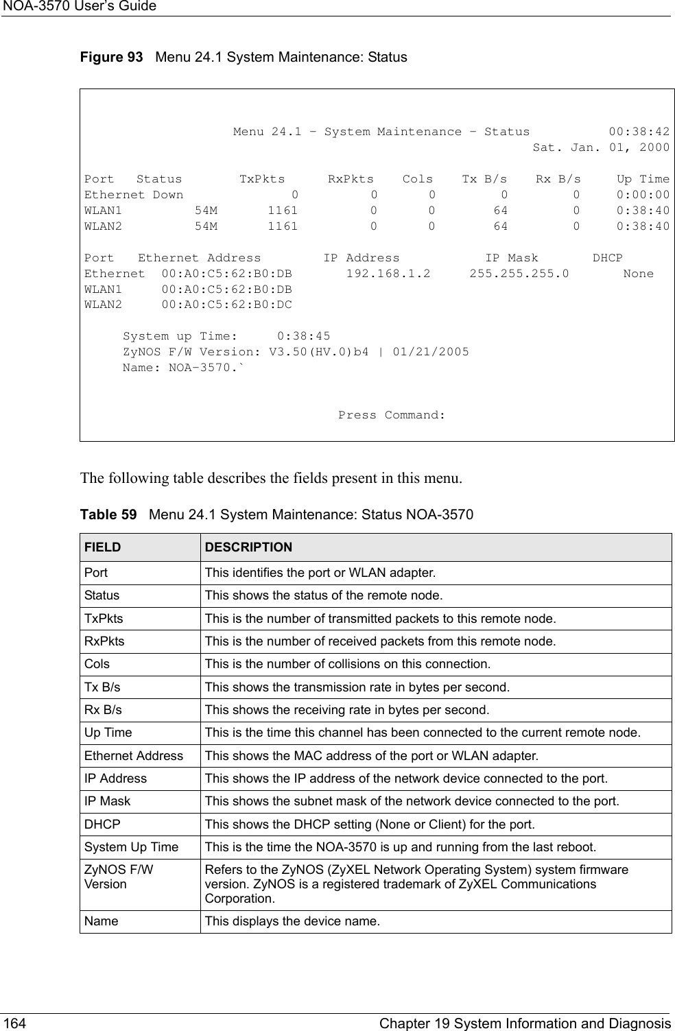
![NOA-3570 User’s GuideChapter 19 System Information and Diagnosis 163CHAPTER 19System Information andDiagnosisThis chapter covers the information and diagnostic tools in SMT menus 24.1 to 24.4.These tools include updates on system status, port status, log and trace capabilities and upgrades for the system software. This chapter describes how to use these tools in detail.Type 24 in the main menu and press [ENTER] to open Menu 24 – System Maintenance, as shown in the following figure.Figure 92 Menu 24 System Maintenance19.1 System StatusThe first selection, System Status gives you information on the status and statistics of the ports, as shown next. System Status is a tool that can be used to monitor your NOA-3570. Specifically, it gives you information on your Ethernet and Wireless LAN status, number of packets sent and received.To get to System Status, type 24 to go to Menu 24 – System Maintenance. From this menu, type 1. System Status. There are two commands in Menu 24.1 – System Maintenance – Status. Entering 9 resets the counters; pressing [ESC] takes you back to the previous screen.The following table describes the fields present in Menu 24.1 – System Maintenance – Status which are read-only and meant for diagnostic purposes. Menu 24 - System Maintenance 1. System Status 2. System Information and Console Port Speed 3. Log and Trace 4. Diagnostic 5. Backup Configuration 6. Restore Configuration 7. Upload Firmware 8. Command Interpreter Mode 10. Time and Date Setting Enter Menu Selection Number:](https://usermanual.wiki/Senao-Co/OA35705001.Manual-Pt2/User-Guide-620617-Page-33.png)
![NOA-3570 User’s Guide166 Chapter 19 System Information and Diagnosis19.2.2 Console Port SpeedYou can set up different port speeds for the console port through Menu 24.2.2 – System Maintenance – Console Port Speed. Your NOA-3570 supports 9600 (default), 19200, 38400, 57600 and 115200 bps console port speeds. Press [SPACE BAR] and then [ENTER] to select the desired speed in menu 24.2.2, as shown in the following figure.Figure 96 Menu 24.2.2 System Maintenance: Change Console Port SpeedAfter you changed the console port speed on your NOA-3570, you must also make the same change to the console port speed parameter of your communication software.19.3 Log and TraceYour NOA-3570 provides the error logs and trace records that are stored locally. Table 60 Menu 24.2.1 System Maintenance: Information NOA-3570FIELD DESCRIPTIONName Displays the system name of your NOA-3570. This information can be changed in Menu 1 – General Setup.Routing Refers to the routing protocol used.ZyNOS F/W Version Refers to the ZyNOS (ZyXEL Network Operating System) system firmware version. ZyNOS is a registered trademark of ZyXEL Communications Corporation.Country Code Refers to the country code of the firmware. LANEthernet Address Refers to the Ethernet MAC (Media Access Control) of your NOA-3570.IP Address This is the IP address of the NOA-3570 in dotted decimal notation.IP Mask This shows the subnet mask of the NOA-3570.DHCP This field shows the DHCP setting of the NOA-3570. When you have completed this menu, press [ENTER] at the prompt “Press ENTER to confirm or ESC to cancel” to save your configuration or press [ESC] to cancel and go back to the previous screen.Menu 24.2.2 – System Maintenance – Change Console Port SpeedConsole Port Speed: 9600Press ENTER to Confirm or ESC to Cancel:](https://usermanual.wiki/Senao-Co/OA35705001.Manual-Pt2/User-Guide-620617-Page-36.png)
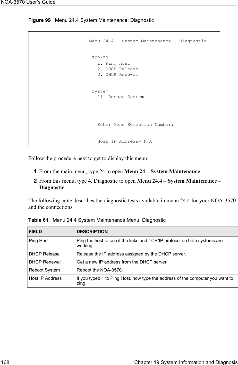
![NOA-3570 User’s GuideChapter 19 System Information and Diagnosis 16719.3.1 Viewing Error LogThe first place you should look for clues when something goes wrong is the error log. Follow the procedures to view the local error/trace log:1Type 24 in the main menu to display Menu 24 – System Maintenance.2From menu 24, type 3 to display Menu 24.3 – System Maintenance – Log and Trace.Figure 97 Menu 24.3 System Maintenance: Log and Trace3Enter 1 from Menu 24.3 – System Maintenance – Log and Trace and press [ENTER] twice to display the error log in the system.After the NOA-3570 finishes displaying the error log, you will have the option to clear it. Samples of typical error and information messages are presented in the next figure.Figure 98 Sample Error and Information Messages19.4 DiagnosticThe diagnostic facility allows you to test the different aspects of your NOA-3570 to determine if it is working properly. Menu 24.4 allows you to choose among various types of diagnostic tests to evaluate your system, as shown in the following figure.Menu 24.3 - System Maintenance - Log and Trace 1. View Error LogPlease enter selection:55 Sat Jan 1 00:00:00 2000 PP05 ERROR Wireless LAN init fail, code=-1 56 Sat Jan 1 00:00:01 2000 PP07 INFO LAN promiscuous mode <1> 57 Sat Jan 1 00:00:01 2000 PINI INFO Last errorlog repeat 1 Times 58 Sat Jan 1 00:00:01 2000 PINI INFO main: init completed 59 Sat Jan 1 00:00:02 2000 PP05 -WARN SNMP TRAP 3: link up 60 Sat Jan 1 00:00:30 2000 PSSV -WARN SNMP TRAP 0: cold start 61 Sat Jan 1 00:01:38 2000 PINI INFO SMT Session Begin 62 Sat Jan 1 00:06:44 2000 PINI INFO SMT Session End 63 Sat Jan 1 00:11:13 2000 PINI INFO SMT Session BeginClear Error Log (y/n):](https://usermanual.wiki/Senao-Co/OA35705001.Manual-Pt2/User-Guide-620617-Page-37.png)
![NOA-3570 User’s GuideChapter 20 Firmware and Configuration File Maintenance 169CHAPTER 20Firmware and Configuration FileMaintenanceThis chapter tells you how to backup and restore your configuration file as well as upload new firmware and configuration files using the SMT screens.20.1 Filename ConventionsThe configuration file (often called the romfile or rom-0) contains the factory default settings in the menus such as password and TCP/IP Setup, etc. It arrives from ZyXEL with a rom filename extension. Once you have customized the NOA-3570's settings, they can be saved back to your computer under a filename of your choosing. ZyNOS (ZyXEL Network Operating System sometimes referred to as the “ras” file) is the system firmware and has a “bin” filename extension. With many FTP and TFTP clients, the filenames are similar to those seen next. ftp> put firmware.bin rasThis is a sample FTP session showing the transfer of the computer file " firmware.bin" to the NOA-3570.ftp> get rom-0 config.cfgThis is a sample FTP session saving the current configuration to the computer file config.cfg.If your [T]FTP client does not allow you to have a destination filename different than the source, you will need to rename them as the NOA-3570 only recognizes “rom-0” and “ras”. Be sure you keep unaltered copies of both files for later use.](https://usermanual.wiki/Senao-Co/OA35705001.Manual-Pt2/User-Guide-620617-Page-39.png)
![NOA-3570 User’s GuideChapter 20 Firmware and Configuration File Maintenance 171Figure 100 Menu 24.5 Backup Configuration20.2.2 Using the FTP command from the DOS Prompt1Launch the FTP client on your computer.2Enter “open” and the IP address of your NOA-3570. 3Press [ENTER] when prompted for a username.4Enter your password as requested. The default is 1234.5Enter “bin” to set transfer mode to binary.6Use “get” to transfer files from the NOA-3570 to the computer, for example, “get rom-0 config.rom” transfers the configuration file on the NOA-3570 to your computer and renames it “config.rom”. See earlier in this chapter for more information on filename conventions.7Enter “quit” to exit the FTP prompt. Menu 24.5 – Backup ConfigurationTo transfer the configuration file to your workstation, follow the procedure below:1. Launch the FTP client on your workstation.2. Type "open" and the IP address of your router. Then type "root" and SMT password as requested.3. Locate the ‘rom-0’ file.4. Type ‘get rom-0’ to back up the current router configuration to your workstation.For details on FTP commands, please consult the documentation of your FTPclient program. For details on backup using TFTP (note that you must remain in the menu to back up using TFTP), please see your router manual. Press ENTER to Exit:](https://usermanual.wiki/Senao-Co/OA35705001.Manual-Pt2/User-Guide-620617-Page-41.png)

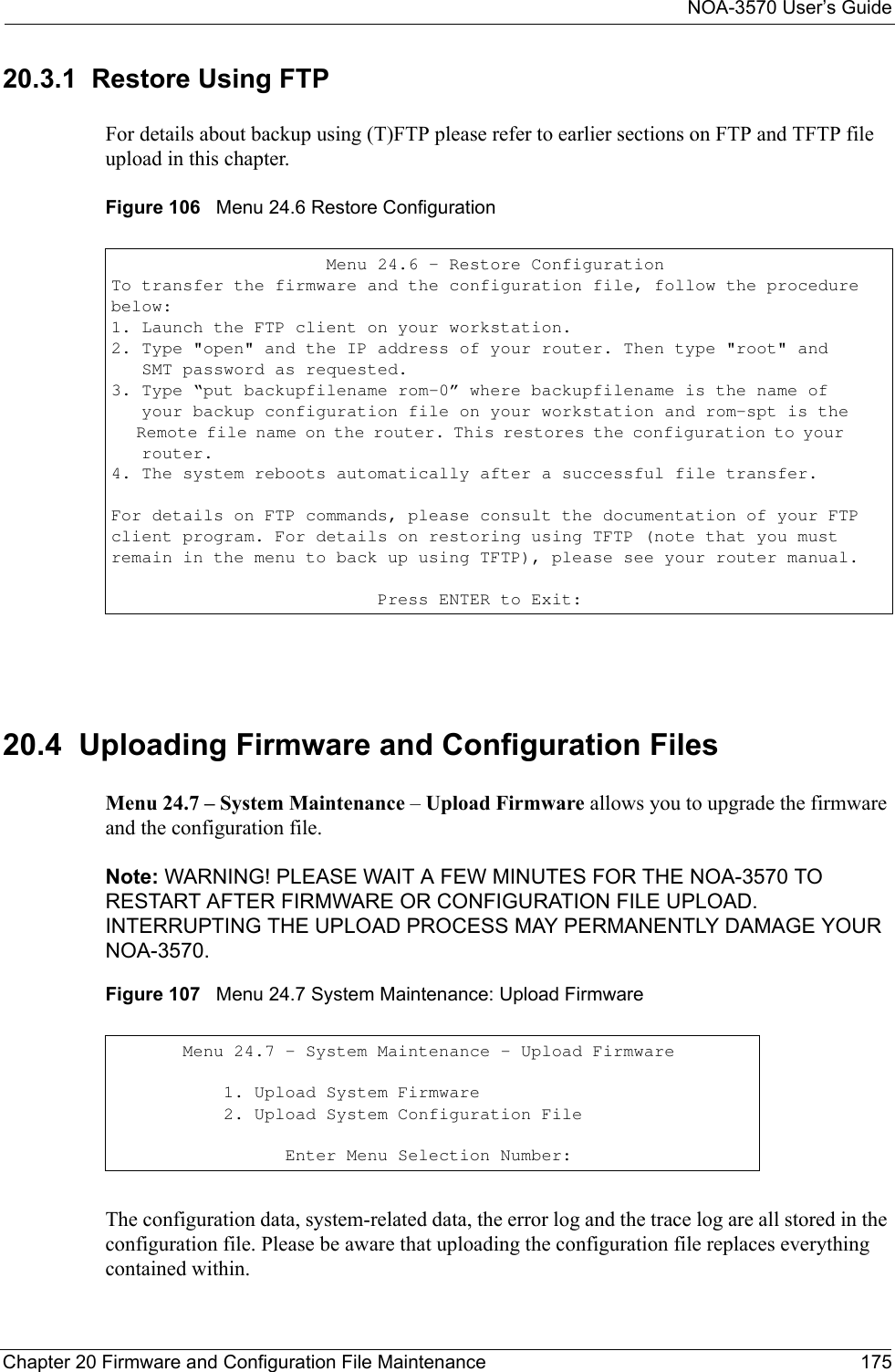
![NOA-3570 User’s GuideChapter 20 Firmware and Configuration File Maintenance 1733Enter command “sys stdio 0” to disable the SMT timeout, so the TFTP transfer will not be interrupted. Enter command “sys stdio 5” to restore the five-minute SMT timeout (default) when the file transfer is complete.4Launch the TFTP client on your computer and connect to the NOA-3570. Set the transfer mode to binary before starting data transfer.5Use the TFTP client (see the example below) to transfer files between the NOA-3570 and the computer. The file name for the configuration file is rom-0 (rom-zero, not capital o).Note that the telnet connection must be active and the SMT in CI mode before and during the TFTP transfer. For details on TFTP commands (see following example), please consult the documentation of your TFTP client program. For UNIX, use “get” to transfer from the NOA-3570 to the computer and “binary” to set binary transfer mode.20.2.4 Example: TFTP CommandThe following is an example TFTP command:TFTP [-i] host get rom-0 config.romwhere “i” specifies binary image transfer mode (use this mode when transferring binary files), “host” is the NOA-3570 IP address, “get” transfers the file source on the NOA-3570 (rom-0 name of the configuration file on the NOA-3570) to the file destination on the computer and renames it config.rom.The following table describes some of the fields that you may see in third party TFTP clients.20.2.5 Backup Via Console Port Back up configuration via console port by following the HyperTerminal procedure shown next. Procedures using other serial communications programs should be similar.1Display menu 24.5 and enter “y” at the following screen.Table 64 General Commands for Third Party TFTP Clients NOA-3570COMMAND DESCRIPTIONHost Enter the IP address of the NOA-3570. 192.168.1.2 is the NOA-3570’s default IP address when shipped.Send/Fetch Use “Send” to upload the file to the NOA-3570 and “Fetch” to back up the file on your computer. Local File Enter the path and name of the firmware file (*.bin extension) or configuration file (*.rom extension) on your computer.Remote File This is the filename on the NOA-3570. The filename for the firmware is “ras” and for the configuration file, is “rom-0”.Binary Transfer the file in binary mode.Abort Stop transfer of the file.](https://usermanual.wiki/Senao-Co/OA35705001.Manual-Pt2/User-Guide-620617-Page-43.png)
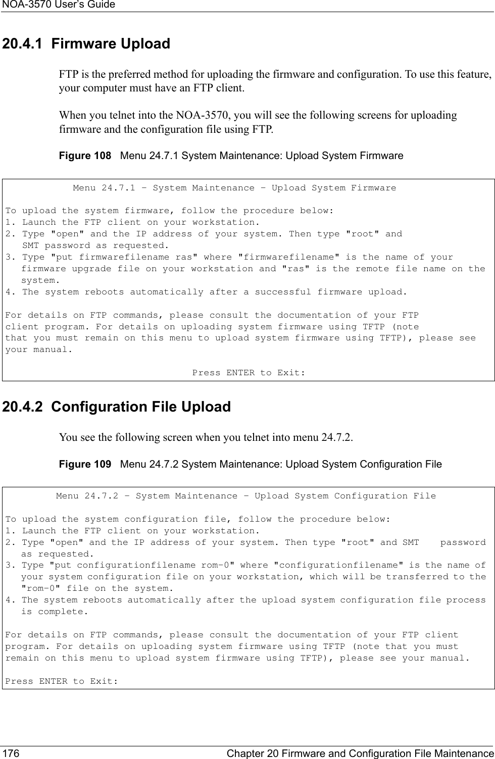
![NOA-3570 User’s GuideChapter 20 Firmware and Configuration File Maintenance 177To transfer the firmware and the configuration file, follow these examples:20.4.3 Using the FTP command from the DOS Prompt Example1Launch the FTP client on your computer.2Enter “open” and the IP address of your NOA-3570. 3Press [ENTER] when prompted for a username.4Enter your password as requested. The default is 1234.5Enter “bin” to set transfer mode to binary.6Use “put” to transfer files from the computer to the NOA-3570, e.g., put firmware.bin ras transfers the firmware on your computer (firmware.bin) to the NOA-3570 and renames it “ras”. Similarly “put config.rom rom-0” transfers the configuration file on your computer (config.rom) to the NOA-3570 and renames it “rom-0”. Likewise “get rom-0 config.rom” transfers the configuration file on the NOA-3570 to your computer and renames it “config.rom.” See earlier in this chapter for more information on filename conventions.7Enter “quit” to exit the FTP prompt.Figure 110 FTP Session ExampleMore commands that you may find in third party FTP clients are listed earlier in this chapter.20.4.4 TFTP File UploadThe NOA-3570 also supports the up/downloading of the firmware and the configuration file using TFTP (Trivial File Transfer Protocol) over Ethernet.To use TFTP, your computer must have both telnet and TFTP clients. To transfer the firmware and the configuration file, follow the procedure shown next:1Use telnet from your computer to connect to the NOA-3570 and log in. Because TFTP does not have any security checks, the NOA-3570 records the IP address of the telnet client and accepts TFTP requests only from this address.2Put the SMT in command interpreter (CI) mode by entering 8 in Menu 24 – System Maintenance.331 Enter PASS commandPassword:230 Logged inftp> bin200 Type I OKftp> put firmware.bin ras200 Port command okay150 Opening data connection for STOR ras226 File received OKftp: 327680 bytes sent in 1.10Seconds 297.89Kbytes/sec.ftp> quit](https://usermanual.wiki/Senao-Co/OA35705001.Manual-Pt2/User-Guide-620617-Page-47.png)
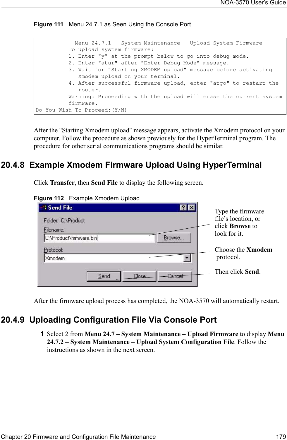
![NOA-3570 User’s Guide178 Chapter 20 Firmware and Configuration File Maintenance3Enter the command “sys stdio 0” to disable the SMT timeout, so the TFTP transfer will not be interrupted. Enter command “sys stdio 5” to restore the five-minute SMT timeout (default) when the file transfer is complete.4Launch the TFTP client on your computer and connect to the NOA-3570. Set the transfer mode to binary before starting data transfer.5Use the TFTP client (see the example below) to transfer files between the NOA-3570 and the computer. The file name for the firmware is “ras” and the configuration file is “rom-0” (rom-zero, not capital o).Note that the telnet connection must be active and the SMT in CI mode before and during the TFTP transfer. For details on TFTP commands (see following example), please consult the documentation of your TFTP client program. For UNIX, use “get” to transfer from the NOA-3570 to the computer, “put” the other way around, and “binary” to set binary transfer mode.20.4.5 Example: TFTP CommandThe following is an example TFTP command:TFTP [-i] host put firmware.bin raswhere “i” specifies binary image transfer mode (use this mode when transferring binary files), “host” is the NOA-3570’s IP address, “put” transfers the file source on the computer (firmware.bin – name of the firmware on the computer) to the file destination on the remote host (ras - name of the firmware on the NOA-3570).Commands that you may see in third party TFTP clients are listed earlier in this chapter.20.4.6 Uploading Via Console Port FTP or TFTP are the preferred methods for uploading firmware to your NOA-3570. However, in the event of your network being down, uploading files is only possible with a direct connection to your NOA-3570 via the console port. Uploading files via the console port under normal conditions is not recommended since FTP or TFTP is faster. Any serial communications program should work fine; however, you must use the Xmodem protocol to perform the download/upload.20.4.7 Uploading Firmware File Via Console Port Select 1 from Menu 24.7 – System Maintenance – Upload Firmware to display Menu 24.7.1 – System Maintenance – Upload System Firmware, then follow the instructions as shown in the following screen.](https://usermanual.wiki/Senao-Co/OA35705001.Manual-Pt2/User-Guide-620617-Page-48.png)
![NOA-3570 User’s GuideChapter 21 System Maintenance and Information 18321.2.1 Resetting the TimeThe NOA-3570 resets the time in three instances:1On leaving menu 24.10 after making changes. 2When the NOA-3570 starts up, if there is a timeserver configured in menu 24.10.324-hour intervals after starting.Table 65 System Maintenance: Time and Date Setting NOA-3570FIELD DESCRIPTIONTime Protocol Enter the time service protocol that your time server sends when you turn on the NOA-3570. Not all time servers support all protocols, so you may have to check with your ISP/network administrator or use trial and error to find a protocol that works. The main differences between them are the format. Daytime (RFC 867) format is day/month/year/time zone of the server.Time (RFC-868) format displays a 4-byte integer giving the total number of seconds since 1970/1/1 at 0:0:0. NTP (RFC-1305) is similar to Time (RFC-868).None The default, enter the time manually.Time Server Address Enter the IP address or domain name of your time server. Check with your ISP/network administrator if you are unsure of this information.Current Time This field displays an updated time only when you reenter this menu.New Time Enter the new time in hour, minute and second format.Current Date This field displays an updated date only when you re-enter this menu.New Date Enter the new date in year, month and day format.Time Zone Press [SPACE BAR] and then [ENTER] to set the time difference between your time zone and Greenwich Mean Time (GMT). Daylight Saving If you use daylight saving time, then choose Yes.Start Date If using daylight saving time, enter the month and day that it starts on.End Date If using daylight saving time, enter the month and day that it ends onOnce you have filled in this menu, press [ENTER] at the message “Press ENTER to Confirm or ESC to Cancel“ to save your configuration, or press [ESC] to cancel.](https://usermanual.wiki/Senao-Co/OA35705001.Manual-Pt2/User-Guide-620617-Page-53.png)

![NOA-3570 User’s Guide186 Chapter 22 Troubleshooting22.3 Problems with the Ethernet InterfaceTable 68 Troubleshooting the Ethernet InterfacePROBLEM CORRECTIVE ACTIONCannot access the NOA-3570 from the LAN.If all of the LEDs on the inline power injector are on, check the Ethernet cable connection between your NOA-3570 and the computer connected to the DATA IN port on the inline power injector.Use a cross-over Ethernet cable to connect the power injector to a computer. Use a straight through Ethernet cable to connect the power injector to a switch or router. Check for faulty Ethernet cables. Make sure the computer’s Ethernet adapter is installed and working properly.If directly connected to the NOA-3570, verify that the IP addresses and the subnet masks of the NOA-3570 and the computer are on the same subnet.Ping the NOA-3570. Make sure your computer’s Ethernet card is installed and functioning properly. In the computer, click Start, (All) Programs, Accessories and then Command Prompt. In the Command Prompt window, type "ping" followed by the NOA-3570’s IP address (192.168.1.2 is the default) and then press [ENTER]. The NOA-3570 should reply. Cannot access the web configurator.You must connect to the NOA-3570’s current IP address and your computer’s IP address must be in the same subnet as the NOA-3570’s IP address.If you don’t know the NOA-3570’s IP address, you can check the IP address in the System Management Terminal (SMT). Use the included console cable to connect the NOA-3570’s console port to a computer running a terminal emulation program set to VT100 terminal emulation, no parity, 8 data bits, 1 stop bit, no flow control and 9600 bps port speed.If the NOA-3570 is set to get an IP address via DHCP, you can check the DHCP server to see which IP address it assigned to the NOA-3570.You may also need to clear your Internet browser’s cache.In Internet Explorer, click Tools and then Internet Options to open the Internet Options screen. In the General tab, click Delete Files. In the pop-up window, select the Delete all offline content check box and click OK. Click OK in the Internet Options screen to close it.If you disconnect your computer from one device and connect it to another device that has the same IP address, your computer’s ARP (Address Resolution Protocol) table may contain an entry that maps the management IP address to the previous device’s MAC address). In Windows, use arp -d at the command prompt to delete all entries in your computer’s ARP table.I cannot ping any computer on the LAN.If the LEDs on the inline power injector are on, check the Ethernet cable connection between your NOA-3570 and the computer connected to the DATA IN port on the inline power injector.Verify that the IP addresses and the subnet masks of the NOA-3570 and the computers are on the same subnet.](https://usermanual.wiki/Senao-Co/OA35705001.Manual-Pt2/User-Guide-620617-Page-56.png)
![NOA-3570 User’s GuideAppendix D Setting up Your Computer’s IP Address 209Figure 128 Windows XP: Internet Protocol (TCP/IP) Properties8Click OK to close the Internet Protocol (TCP/IP) Properties window.9Click Close (OK in Windows 2000/NT) to close the Local Area Connection Properties window.10 Close the Network Connections window (Network and Dial-up Connections in Windows 2000/NT).11Turn on your NOA-3570 and restart your computer (if prompted).Verifying Settings1Click Start, All Programs, Accessories and then Command Prompt.2In the Command Prompt window, type "ipconfig" and then press [ENTER]. You can also open Network Connections, right-click a network connection, click Status and then click the Support tab.Macintosh OS 8/9 1Click the Apple menu, Control Panel and double-click TCP/IP to open the TCP/IP Control Panel.](https://usermanual.wiki/Senao-Co/OA35705001.Manual-Pt2/User-Guide-620617-Page-76.png)

![NOA-3570 User’s GuideAppendix I Command Interpreter 245APPENDIX ICommand InterpreterThe following describes how to use the command interpreter. Enter 24 in the main menu to bring up the system maintenance menu. Enter 8 to go to Menu 24.8 - Command Interpreter Mode. See the included disk or zyxel.com for more detailed information on these commands.Note: Use of undocumented commands or misconfiguration can damage the unit and possibly render it unusable.Command Syntax• The command keywords are in courier new font.• Enter the command keywords exactly as shown, do not abbreviate.• The required fields in a command are enclosed in angle brackets <>. • The optional fields in a command are enclosed in square brackets [].•The |symbol means or.For example,sys filter netbios config <type> <on|off>means that you must specify the type of netbios filter and whether to turn it on or off.Command UsageA list of valid commands can be found by typing help or ? at the command prompt. Always type the full command. Type exit to return to the SMT main menu when finished.](https://usermanual.wiki/Senao-Co/OA35705001.Manual-Pt2/User-Guide-620617-Page-112.png)
![NOA-3570 User’s GuideAppendix K Log Descriptions 251Use sys logs category followed by a log category and a parameter to decide what to record Use the sys logs save command to store the settings in the NOA-3570 (you must do this in order to record logs).Displaying LogsUse the sys logs display command to show all of the logs in the NOA-3570’s log.Use the sys logs category display command to show the log settings for all of the log categories.Use the sys logs display [log category] command to show the logs in an individual NOA-3570 log category.Use the sys logs clear command to erase all of the NOA-3570’s logs.Log Command ExampleThis example shows how to set the NOA-3570 to record the error logs and alerts and then view the results.ras> sys logs loadras> sys logs category error 3ras> sys logs saveras> sys logs display access# .time source destination notes message 0|11/11/2002 15:10:12 |172.22.3.80:137 |172.22.255.255:137 |ACCESS BLOCKTable 109 Log Categories and Available SettingsLOG CATEGORIES AVAILABLE PARAMETERSerror 0, 1, 2, 3mten 0, 1Use 0 to not record logs for that category, 1 to record only logs for that category, 2 to record only alerts for that category, and 3 to record both logs and alerts for that category.](https://usermanual.wiki/Senao-Co/OA35705001.Manual-Pt2/User-Guide-620617-Page-118.png)