Senao Co SN-920U A SPREAD SPECTRUM Telephone User Manual Revised
Senao International Co Ltd A SPREAD SPECTRUM Telephone Revised
Senao Co >
Revised user manual

SN -920 U LTRA
User's Manual

Congratulations
H andset
B ase U nit
C harging Cradle
G e tting Started
B asic O perations
Diagram
Features
Diagram
Features
Diagram
Features
Base Unit S e t-u p
C harging Cradle Set-u p
Modes
Making Calls
M anual Dail Pre-dial tone
M anual Dail Post-d ial tone
Redial
Dire c to ry D ial
M e m o ry Dial
Answering C alls
H andset in C harging Cradle
H andset not C harging Cradle
Voice Volum e
1
3
4
8
9
10
11
12-13
13-15
16-19
20
21
21
21-22
22-23
25
25
26
Table of C ontents
Call On-Hold
Muting a Call
Call Waiting
T ra n s fe rring a Calls
Disconnecting Calls
2-W ay R adio
H andset-to-H andset
Base-to-H andset
H andset-to -B a s e
Base Unit Options
Ring Volum e
Voice Volum e
Main M enu Function C hart
H andset / B a s e Registra tion
Registering a H andset
Registering additional Base Units
H andset M enu O ptions
K ey G uard
Dire c to ry
Caller ID
Sounds
Ring Volum e
Ring Type
Key Volum e
Key Tone
S e ttings
Area Code
Tone/P ulse
B acklight
Reset
A dvanced O perations
De-registering H andset
Custo
m N
a
m
e
26
31
27
28
28-31
32
33
34
35
35
36
39
42
54
54
54
55
56
56
57
37-39
40-41
42-50
50-53
53-54
57
59
60
58-59
Call M anager
C o n tra s t
Dial Prefix
Product Specifications
S a fe ty In s tru c tion
Regulatory Inform ation
EnG enius Product G uide
61
67-68
69
62-66
This device com plies with Part 15 of the FCC Rules.
O peration is subject to the follow ing tw o conditions:
1)this device may not cause harm ful interference, and
2)this device must accept any interference received ,
including interference that may cause undesire d
operation.
Privacy of com m u nications m ay not be en sured w hen using
th is phone.
W hen selecting a location fo r th e base unit, it is bette r to locate
th e base unit as high as possible to avoid obstructions th a t
might interfere with the ra d io tra n s m ission and g e tting a clear
signal.
In any case, the base unit must be located 8 inches (20cm )
fro m any person to be in com pliance of FCC s a fe ty re g u lations.
In any case, the base unit must be located 8 inches (20cm )
fro m any person to be in com pliance of FCC s a fe ty re g u lations.
Person with pacem aker: Should alw ays keep th e handset
more than 20 cm (6 inches) fro m th e ir pacem aker w hen th e
handset is sw itc h on. Should not c a rry th e handset in a breast
pocket. If yo u have any reason to suspect th a t interference is
ta lking place, sw itch off you handset immediately.
For body-w orn h a n d s -fre e operation of th e handset, the device
has been tested for RF exposure com pliance with the
E nG enius provided belt-c lip and leather pouch. O ther belt-
clips, holsters or similar accessories th a t have not been tested
m ay not co m p ly with RF exposure requirem ents and sh ou ld
not be used.
CAUTION:

You have p urchased an excep tional b usiness com m unications
tool fro m the leading Industrial Cordless Phone System
m anufacturer.
The EnG enius SN-920 ULTRA Industrial C o rd less Phone
S ystem is th e second generation of the
system . EnG enius system s
are ideal for th e Sm all Office H om e Office (SO H O ) user. The
expandable design allow s the system to grow w ith your business.
With sophisticated digital signal processing and six tim es th e
pow er of typical cord less phones, the EnG enius system provides
cord less phone and tw o-w ay com m unications in a wid e v a riety of
business settings fro m multi-level office buildings, construction
sites, w arehouses, fa rm s , b usiness com plexes and other
dem anding business environm ents. The EnG enius system is
capable of supporting up to 4 lines (4 b ase units) and 36
handsets. The EnG enius system is able to provide you increased
mobility with in your b usiness environm ent.
Another unique fe a ture of th e EnG enius system is the ability to
use the handsets as digita l, full duplex, tw o-w ay radios. The
digita l two-way radio mode allow s members of th e work group to
be in contact with th e ir c o -w o rk e rs while leaving phone lines
available for incom ing or outgoing calls. Users can designate
their handsets to re c e ive all incom ing calls or re c e ive only
intercom (2 -w a y ) a n d transferred calls, with th e Call M anager
fe a tu re . Additionally, an incom ing call can be answ ered, placed
on-hold or transferred to th e appropriate person, fro m any
handset.
The m any EnG enius system fe a tu re s include: long-range, 2-w ay
radio and cordless phone operation, system expandability,
milita ry level digital security, music or m essag e on-hold capability,
80 minute batte ry recharge and th e new 4-line LC D display w ith
Caller ID/Call Waiting readout capability have given birth to a new
product c a te g o ry in th e c o rd less phone industry know n as
Ind ustrial Cordless Phone S ystem s. The convenience, m obility
TM
TM
TM
Longest R ange
Cordless Phone and 2-W ay Radio
C ongratulations!
~1~
and flexibility of this unique telecom m unications system cannot
be overlooked fo r the Sm all Office / Hom e environm ent.
~2~
In te lle c tu a l Property Rig h ts N o tice
EnG enius SN -920 ULTRA User's M anual
Copyrig ht 2000 EnG enius Technologies.
All rights reserved.
N o part of this U ser's M anual m ay be reproduced, stored in a
re trievable system , or transm itted, in any form or by any m eans,
electronic or m echanical, including photocopying, re c o rd ing, or
otherw ise, without perm ission of EnG enius Technologies.
EnG enius is a tradem ark used herein under exclusive license and
Ind ustrial Cordless is a tra d e m a rk of EnG enius Technologies.
All rights to patents, includ ing patents pending EnG enius
products are the exclusive properties of EnG enius Technologies.
α
TM

~3~
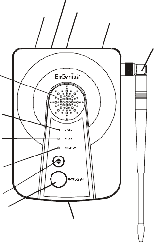
H andset D iagram
1. Antenna
17. Status LED
2. Earpiece
16. End/O N /O FF
7. Volum e key
5. K eyp ad
8. 2 w ay/Intercom¡E
3. M icrophone
12. H eadset Adapter Port
9. Dialing keys
6. Ta lk/Flash
14. Right Soft Key
15. Scrolling Keys
4. LC D
~
~
~4~
H andset Features
1. Antenna
2. E a r p ie c e
3. M icrophone
4. Liquid C rystal D isplay (LCD)
*
*
*
*
* R eceive Signal Strength Indicator (RSSI)
* C a ll in-progress(O N /O FF H ook)
* Intercom M ode: Active
* H andset ID
Functions as m outhp iece.
The display has Light Em itting D iode (L E D ) fo r backlighting.
The firs t line of th e LC D consists of eight icons.
The next tw o lines consist of user-p ro g ra m m a b le alphanum eric
C h a ra c te rs .
The last line displays the soft key fu n c tions.
The num ber of bars is
proportional to th e signal
strength of th e RF signal
received .
~6~
7. Volum e key
(not show n)
17. Status LED
Located on side of handset: up / dow n buttons contro l vo lum e
.
Blinking: Stand by
Solid: O n a call or the firs t 8 seconds after power on
8. 2-W A Y /IN T E R C O M
9. D ialing K eyp ad
10. Ringer (not show n)
Single Beep
D ouble B eep
Periodic Short Single Beep
Periodic Long Series of Beeps
C ontinuous B eep
11. Battery Pack Slot (on back of handset)
12. H eadset A dapter Port (on bottom of handset)
13. Left Soft Key
14. Right Soft Key
1 5 . S c r o llin g Keys
16. EN D
U sed to place an intercom call to another handset or base.
U sed for dialing phone num bers and entering alphanum eric
inform ation into Phone D ire c tory.
Em its several sounds to ind icate various events or alarm s.
S uccessful operation
Failed operation or invalid key. Also, ind icates
pow er on / off.
(every tw o seconds):
Low battery warning.
(repeat every 30 seconds):
Indicates a call on-hold.
(2 seconds): Ind icates out of range while
in talk m ode.
On / Off for power and to end (hang-up) a call
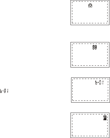
* C a lle r ID Log
* Tw o -d ig it N um ber D isplay
* Line or Base Indicator
* B a tte ry Strength
5. K eyp ad
6. Ta lk / Flash
U nread m essag es: Closed E nvelope
Read m essages: O pen E nvelope
No inform ation or no Caller ID Service:
N o Envelope is Displayed .
Tracks Caller ID log and Phone
Dire c to ry re c o rd location.
Ind icates th e b ase that is active .
(E x a m p le: )
Num ber of bars is proportional to the
am ount of battery time re m a ining.
Answ er incom ing phone or tw o-w ay
radio (intercom ) call. Place an
outgoing phone call.
This button also acts as the flash
button fo r functions like call waiting
and toggling between calls.
19 button face keypad.
Backlight option can be set to OFF,
ON, or 8 seconds time out.
~5~
~7~
Additional H andset Features
*
*
*
*
*
*
*
Call Waiting with C a ller ID (re q u ires Call Waiting and Caller ID
services fro m local phone service provider)
Call M anager option: U ser program m able option for handset to
allow all calls or only tra n s fe rre d and intercom calls
Touch any key to answ er call
Call transfer to another handset with in the system
Unique, system assigned Security ID (1 o f 65,000)
Phone Dire c tory: up to 30 phone num bers (2 0 d igits ) a n d
Flash
nam es (14 characters)
30 num ber memory sp eed dial fo r Phone Directory
Last num ber redial
Caller ID (require s Caller ID service from phone service provider)
Caller ID log: stores up to 30 calls of caller inform ation including
caller's nam e, num ber, date and time
Intercom com m unications w ith b a s e unit
H andset-to -h a n d s e t com m unication independent of th e base
(D igita l, fu ll duplex tw o -w a y ra d io)
Three level ringer vo lum e ad justment (low, high & vib rate)
Four ring types
Six level voice volum e contro l adjustm ent
Ring or vibration alert option
To ne / pulse dial option
Low battery alarm and disp lay
C hange batte ry while call on-hold
Keypad illum ination
Three level ke y tone volum e contro l (low, high & off)
Four different key to n e sound selections
Auto pow er m anagem ent
Hold
Mute
*
*
*
*
*
*
*
*
*
*
*
*
*
*
*
*
*
*
*
~8~
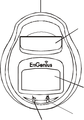
B ase U nit Diagram
INDUSTRIAL CORD LESS PH ON E S YST EM
SN -920 ULTRA
VO LU M E
PA G E
1. A ntenna
2. Speaker
12.AC adaptor
11. Line In
10. Line O ut
6. A udio-in Jack
7. Pow er LED
8. In use LED
9. In te r c o m L E D
4. P a g e / In te r c o m
5. M icrophone
3. Volum e
~9~
B ase U nit Features
Additional Base Unit Features
1. A ntenna
2. Speaker
3. Volum e
4. P a g e / In te r c o m
5. M icrophone
6. A udio-in Jack(3.5 m m )
7. Pow er LED
8. In Use LED
9. In te r c o m L E D
10. Line In
11. Line O ut
12. AC Adapter Port
*
*
*
Swivel base for ease of positioning . (N o te: R e v e rs e th read
antenna adapte r; to rem ove, tu rn clockw ise).
LED ind icates base unit has AC power.
LED ind icates a phone call, base / handset intercom call, or
handset regis tra tion is in prog ress.
LED ind icates w hen base is in intercom m ode.
Supports up to 9 handsets p er base unit. O ne handset can be
registered to 4 b ase units.
A ssigns handset security code during registra tion
Adjustab le four level ringer and voice volum e control
~ 10~
C harging Cradle Diagram
2. S p a re B a tte ry
C om p artm ent
1. H andset C harger/C radle
3. H andset C harging Indicator
4. S p a re B a tte ry Charging Indicator
5. AC A dapter
~ 11~
C harging Cradle Features
1. H andset C harging C radle
2. S p a re B a tte ry Com partm ent
3. H andset C harging Indicator
4. S p a re B a tte ry Charging Indicator
5. AC A dapter Port
*
*
*
*
Holds handset
C harges handset batte ry pack each time handset is placed
in cradle. 80 m inute rapid charge.
Spare battery recharged w hen placed in this slot.
LE D is not lit: Slot is em pty or proper connection is not
m ade.
LE D is blinking red: Batte ry is charg ing.
LE D is green: Batte ry is fully charged.
LE D is not lit: Slot is em pty or proper connection is not
m ade.
LE D is blinking red: Batte ry is charg ing.
LE D is green: Batte ry is fully charged.
H and set and a spare battery pack can be charged at th e sam e
time
Fully d ischarged battery packs can be charged in
approximately 80 minutes
A trickle charge fe a tu re will maintain charge on a nearly fu lly
charged battery
It is im p ossible to overcharge th e batteries using this charg er
80 minute ra p id charg e.
Fully charg e battery packs before firs t use
Additional Charging Cradle Features
*
~ 12~
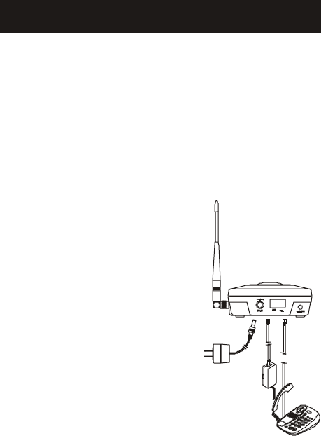
B ase U nit Setup
There are three p o s s ib le base unit setups:
*
*
*
Basic Instructions
B ase unit alone
B ase unit plus telephone answ ering device
B ase unit plus standard telephone
1. Plug the sm all end of the 9V DC power adapter into the
"DC IN" port on the back of the base unit.
2. Plug the tw o-pronged 9V D C
pow er adapter into a standard
120 V AC ele c trical o u tlet.
3. Plug telephone lin e c o rd into
the next receptacle on the
back m arked LINE.
4. Plug the telephone lin e c o rd into
the te lephone wall outlet.
5. A standard te lephone or answ ering
machine can be plugged into the
ad jacent recep tacle on th e back of the
base unit m arked TEL.
6. The M usic/M essag e On-Hold feature can
be achieved by plugging either end of th e
included audio cable into th e audio-in port
on the back of the base unit.
7. For best perform ance, com puters, faxes, te lephone answ ering
machines, televisions, stereos and other c o rd less devices
should be at least 1 m eter (approximately 3 fe e t) fro m th e
base unit.
G ETTING STARTED
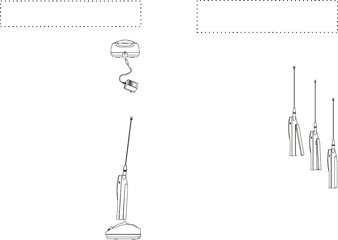
~13~
The location for the handset charging
require s a standard 120V AC
electrical wall o u tlet.
1. Plug the sm all end of the 12V
DC adapter into the re c e p tacle
on th e back of th e charger unit.
2. The tw o -p ro n g e d 12V DC adapter
is then plugged into th e wall outlet.
The batte ry charger can charg e th e handset and
a spare battery pack at th e sam e time.
The charging unit has spare battery charging slot
behind th e handset charg ing slot.
1. To charge the handset, simply p lace th e
handset, with battery pack attached, into
th e charging slot with the handset facing
th e fro n t of the charger. If th e handset is
properly in the cradle, the cradle's
PHO NE indicator light will be illum inated.
2. To simultaneously charg e a sp are
battery, insert th e sp are batte ry pack
with pack contacts facing down and
to w a rd s the re a r into the re a r charging
slot.
C harging SetupCradle
Chargin g a B a tte ry
cradle
Follow instru c tions that cam e w ith th e answ ering
device or telephone if diffe re n t fro m those described here.
NOTE:
~14~
It ta k e s about 80 m inutes to fully charge a battery
in eith e r the (front) handset slot or th e (re a r) s p a re battery
slot.
NOTE:
LE D is not lit: Slot is em p ty or proper
connection is not made.
LE D is b linking re d : Battery charging.
LE D is green: Battery is fu lly charg ed.
1. To rem ove th e handset battery:
T u rn the handset face dow n and
locate the battery pack re lease
on th e bottom of the handset.
Push the re lease tow ards th e
top of the phone and lift up.
2. To install battery pack:
Carefully slide the top batte ry
pack tabs into batte ry pack
area of handset aligning th e
metal contacts of handset
and battery pack. P ress down
on th e bottom end of the battery
pack. The battery p ack should
"c lick" into a secured position
on th e handset.
B attery Light Indicators
*
*
*
In s ta lling N ew Battery

~ 15~
Your EnG enius phone system uses recharg eable Nickel Metal
Hydride (N i-M H ) batte ry packs. Each batte ry provides up to th r e
hours of ta lk -time, based on range, terra in and environm ental
conditions, or up to 40 hours of standby time. These high
perform ance battery p acks have an average life s p a n of about
300 charges (a charge is defined as going fro m em pty to fu lly
charged). Additional or replacem ent new SN-920 ULTRA battery
packs are available as p a rt num ber: SN -920 U LTRA-BA.
D anger of exp losion if battery is incorrectly
replaced. Replace only w ith th e sam e or eq uiva lent type
recom m end ed by the m anufacturer. Disp ose of used
batte ries according to th e manufa c tu re r's instructions.
Do not open th e plastic batte ry pack encasing.
Low Battery In d icator
*
*
*
*
C harge the batteries w hen one of th e fo llow ing happens:
Phone beeps tw ice every tw o seconds
B a tte ry icon is em p ty
Phone d oes not resp ond w hen a key is pressed
LCD and b acklighting becom e dim
B attery R eplacem ent
CAUTION!
CAUTION!
e
~ 16~
ID L E M O D E
TA LK MODE
REGISTRATION M ODE
O peration M odes
B ase O peration M odes
H andsetO peration M odes
B o th the base unit and handset have levels of operation at which
time only certain pro ced ures or functions can b e p e rfo rm e d .
These levels or m odes of operation will b e re fe rre d to throughout
this m anual a n d v a ry from base unit to handset.
The b ase unit operates in three different m od es: IDLE, TA LK , and
REG ISTRATION.
- this is th e default mode. The intercom and volum e
keys are active in ID LE m ode. The PO W ER LED is re d .
- the base operates in this m ode during an
incom ing or outgoing intercom call and an incom ing or outgoing
phone call. Volum e key is active in TA LK m ode. PO W ER, IN USE
and INTERCO M (during an intercom call) L E D s are re d .
- the base enters this m od e by
simultaneously holding down the intercom and vo lum e keys for
three seconds. There are no active b ase unit ke ys o nc e this m ode
has been entered. The IN USE and PO W ER LED s are illum inated.
The IN USE LED will com e on and stay active for approximately
30 seconds and then tu rn o ff.
The handset operates in one of five different m od es: IDLE,
M ENU, TA LK , REG ISTRATION and CRADLE.
BASIC OPERATIO NS
~ 17~
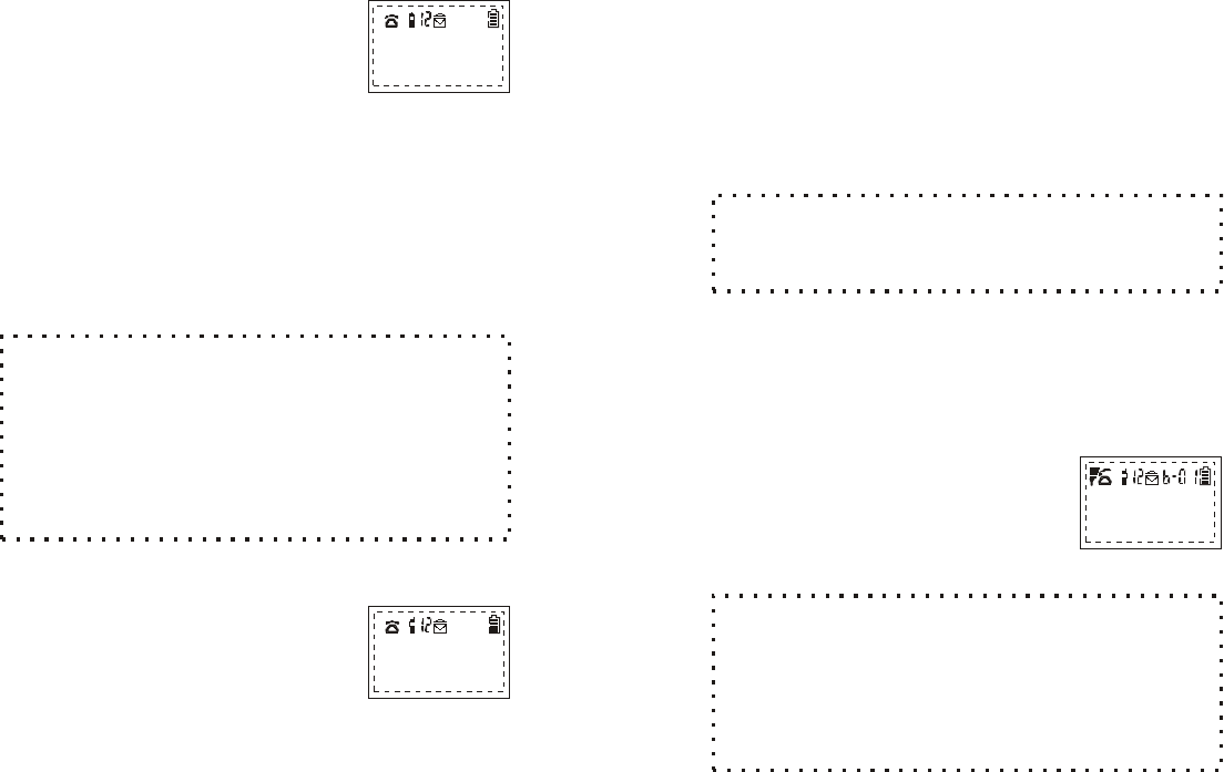
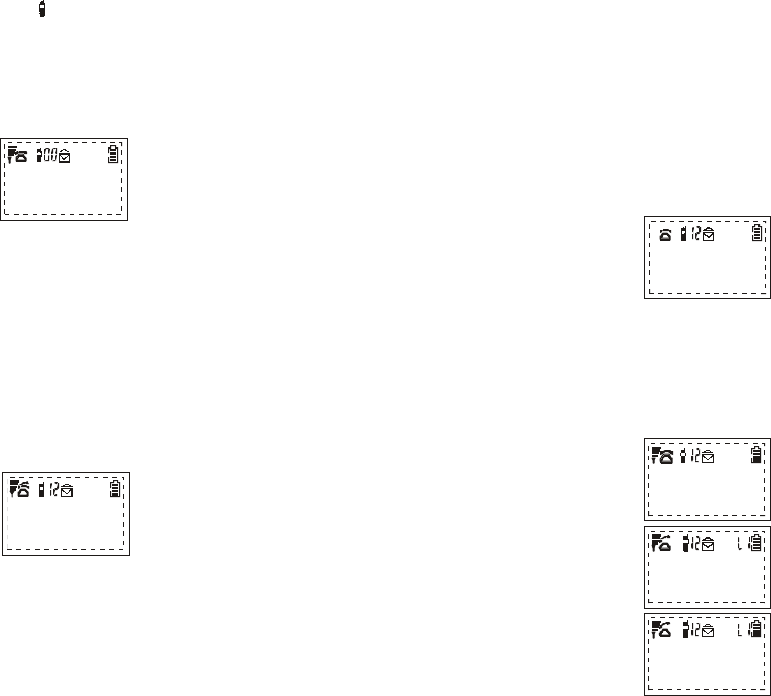
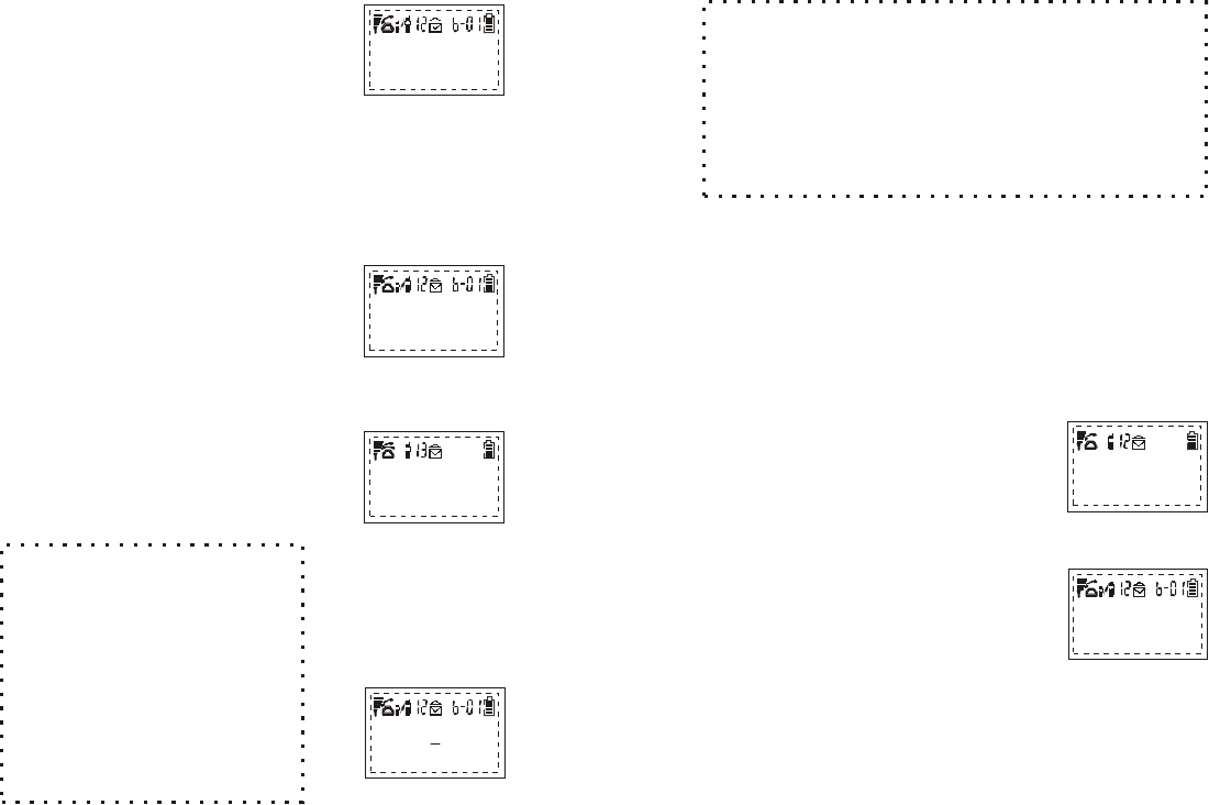
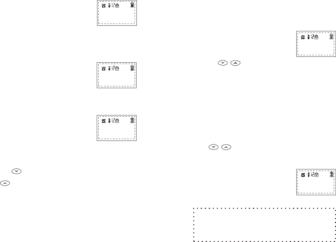
ID L E M O D E
This is th e default operating m ode.
* The LC D will show the follow ing
screen and icon placem ent in th e
ID LE m ode:
* If th e re is no on-going activity, the
handset autom atically goes into
SLEEP/IDLE mode to save battery
power.
* The handset can be turned off
com pletely by holding dow n th e
END key for 3 second s.
The idle screen disp lay(custom nam e) can be
edite d (in th e m enu m ode) with the handset ow ner's nam e
or other custom greeting .
The 2-digit num ber near th e top center of the LC D show s
the handset's ID.
NOTE:
EnG enius
SN-920
REDIAL M ENU
M ENU M ODE
*
*
Pressing th e RIGHT SO FT FUNCTION
key activates MENU m ode.
The screen will look like th is in MENU
Mode:
Main M enu:
1:KEY GUA D
2:DIRECTORY
¡õ¡ô
R
3:CALLER ID
4:SOUNDS
5:SETTIN G S
6:REGISTER
~ 18~
NOTE:
The functions availab le through the MENU
selection are covered in greater detail under H andset
Menu Options.
In MENU m ode, th e handset
setting s and inform ation
contained in memory can be
changed. (F o r exam ple: the Caller
ID log and Phone D ire c to ry ).
All ke ys, except 2-W AY , are
active in M EN U m ode
If the handset re m a ins inactive in MENU mode for 30 seconds
(no keys are pressed or no incom ing calls ), it will exit MENU
m ode and re turn to IDLE mode
*
*
*
(Intercom )
TA LK MODE
*
*
*
W hen the handset is in IDLE mode,
p ressing the TA LK key or answ ering
an incom ing or intercom call will
activa te TA LK Mode.
The screen will look like th is in
TA LK Mode:
All ke ys are active in th e TALK M ode.
In th e TA LK m ode the TA LK key functions as a
FLASH key. P ressing the TA LK key will tem porarily p lace
the call on hold w hile answ ering another call with the Call
Waiting fe a tu re . P ressing th e TA LK key again will re tu rn you
to the original call. Call Waiting require s te lephone service
provider subscription.
NOTE:
00:00:08
Volum e 5
HOLD M UTE
~ 19~
* Do not re g ister your handset if it has been re g istered at th e
factory. If, w hen you firs t tu rn on th e phone, "0 0 " is displayed
near th e top center of the LC D (to th e right of th e icon),
th e handset has not been registered at the factory.
* Specific in s tru c tions on how to register th e handset are
covered in detail und er H and set / B ase R egis tra tion in th e
Advanced O perations section.
* If the handset is not re g istered
with the base unit, any attem pt
to m ake an outgoing call or
intercom call to another handset
will fail. The LC D will re a d :
REGISTRATION M ODE
CRADLE M ODE
* Placing th e handset into the charg er
cradle activates the handset CRADLE
m ode.
* While in the CRADLE m ode, th e battery
charging unit recharg es the handset
battery pack.
* An incom ing or intercom call while
in th e C RADLE mode will generate
th is screen:
* Rem oving th e handset fro m the
cradle during an incom ing call
autom atically answ ers th e call and
places the handset in TA LK M ode.
* Placing th e handset in th e cradle
or p ressing END will end a call.
Incom ing C all
On Base 1
SILENT
S tation not
registered
~ 20~
Making C alls
You can enter a phone num ber before or after connecting to dial
tone.
Selecting a phone num ber before connecting to dial tone offers
the advantage of reaching th e c o rre c t p a rty with th e firs t phone
call.
M anualD ial(Pre-D ial Tone)
ENTERING A N UM BER BEFORE CONNECTING TO
DIAL TONE
*
*
*
*
*
From th e ID LE m ode, enter the num ber
you w ish to call. The num ber you input
will appear on th e handset screen as
typed. For exam ple, the num ber
555-1221 w ould appear as:
If an incorrect num b er has been entered,
select the C LEAR option by pressing th e
RIGHT SO FT FUNCTION key to clear th e
entire num ber, then re -e n te r the num ber
you w ish
The D E LE TE option is selected by
pressing the LEFT SO FT FUNCTION
key. D ELETE will delete one digit
at a time fro m right to left, similar
to a backspace key
W hen th e c o rre c t num b er is displayed
on th e screen, press TA LK to com plete
th e call
You will hear a dial tone and see the
follow ing three screens as the num b er is
dialed :
5551221_
D ELETE CLEAR
Connecting
to Line 1
Dialing
5551221
00:00:08
Volum e: 5
HOLD M UTE
~ 21~
M anual Dial(P o s t-D ia l T o n e )
ENTERING A NUM BER AFTER CONNECTING TO
DIAL TONE
*
While the handset is in the IDLE m ode, you can press TA LK to
make a call. There are three ways to m ake a call in th e TA LK
Mode:
* W hen dial tone is heard and
th e handset is waiting for a phone
num ber to be entered, the follow ing
screen w ill appear:
* Enter th e d esired phone num ber
fro m th e num bered key pad. The
screen w ill show th e fo llow ing
display:
* After a num ber is dialed, this
screen w ill be displayed :
While in th e TA LK m ode, press the
LEFT SO FT FUNCTIO N ke y to select
th e REDIAL option. The follow ing
screen w ill be displayed :
* The last num ber dialed w ill be re -
dialed
To call a num ber stored in th e Phone
Dire c tory, you can access the Phone
Dire c tory log by e n te ring the m enu or
you can simply press the Up or Down
Scrolling Arrow s to access the Phone
Redial
Dire c to ry D ia l
*
5551222
V O L U M E : 5
REDIAL M EM ORY
00:00:00
V O L U M E : 5
HOLD M UTE
DIALING
5552222
~ 22~
From IDLE mode, press the RIGHT
SO FT FUNC TION key to select th e
MENU option.
While in the Main M enu, select th e
dire c tory scolling option by pressing
th e 2 key.
Inform ation stored in location 01 w ill
be displayed firs t. U se the U p or
D o w n a rro w s to scroll through the
dire c tory to locate th e num ber of
your choice.
Press TA LK to dial the phone
num ber displayed .
W hen the handset has dialed the
selected phone num ber, th e screen
will disp lay:
*
*
*
*
*
ADD OPTIO N
See Dire c tory View M ode for additional instru c tions
on how to use th e phone dire c tory fe a tu re .
If th e handset is unable to link to th e base unit, it will re turn
to IDLE m ode. The handset will disp lay "N o C onnection" fo r
five seconds or until a key is pressed .
NOTE:
00:00:00
V O L U M E : 5
HOLD M UTE
Sm ith
5551212
In the TA LK mode, the follow ing
screen w ill be displayed :
* To select MEMORY DIAL, press the
RIGHT SO FT FUNCTION key.
Memory Dial
*
V O L U M E : 5
REDIAL M EM ORY
~23~
* The follow ing screen will appear:
* Enter th e 2 digit Phone Dire c tory
index code (e .g. 1 = 0 1 )fo r the stored
phone num ber.
* The phone num ber stored in th e
location will be dialed.
NOTE:
Te lephone num bers stored in the Phone D ire c to ry
have been indexed with a num ber fro m 01 to 30. To access
the correct index num ber or location, follow these step s:
For exam ple, if the location is 3, p ress 0 then 3.
If th e ind ex num ber is 12, press 1 then 2.
Answ ering C alls
All handsets th a t have been re g istered for use with the base unit,
and are in the IDLE m ode, will ring w hen an incom ing call is
re c e ived. The handset can be set to eith e r ring or vibrate with an
incom ing call.
NOTE:
Under SETTINGS, th e user has th e option of
re c e iving incom ing/intercom /transfe rre d c a lls fro m 1 to 4
base units . This option is accessed via th e Call M anager
function, under SETTING. D epending upon num ber of
base units the handset is registered to .
LOCATION:??
~24~
Receiving an in c o m in g call
Receiving an in c o m in g call w ith calle r ID
service **
* H and set is on th e charger
cradle-N o caller ID service
* H and set is off th e cradle-N o
caller ID service
Incom ing C all
On Base 1
SILENT
* Caller ID service, but the ID has
been blocked by the caller:
* Caller ID service, but n o t supported
by th e originating party:
* Caller ID service, but only the
num ber has been tra n s m itted:
* Caller ID service, all inform ation
has been transm itted:
Private Nam e
Private
U n kn ow n N am e
U n kn ow n
Private Nam e
555-1212
H a yter, S
555-1212
~26~
Voice Volum e
Placing a C a ll On-Hold
Adjusting the volum e on th e handset can be done only during a
call or w hen in the TA LK M ode.
* W hen in th e TA LK Mode, the volum e contro l button on th e left
side of th e handset can be used to adjust th e volum e to 6
different levels.
* Volum e level 3 is set as default.
* The top butto n increases vo lum e and the low er butto n
d ecreases volum e.
* The screen during vo lum e ad justment
displays the follow ing:
1. When a call is in prog ress it can be
put on hold by pressing th e LEFT
SO FT FUNC TION key which selects
th e HOLD option:
The display will then show :
2. To bring the call back on line, press
th e LEFT SO FT FU N C TION key ag ain.
The display will re turn to this screen:
The handset w ill double beep three tim es every 30
seconds when a c a ll is on hold as a re m inder that you
V O L U M E : 5
REDIAL M EM ORY
V O L U M E : 5
HOLD M UTE
00:00:00
Call hold L1
UNHOLD M ENU
V O L U M E : 5
HOLD M UTE
~25~
: The firs t handset to answ er a call will connect to
the base unit and will operate in TALK m ode. Other
registered handsets w ill be locked out of the call. H ow ever
they will still be able to p a rticipate in handset to handset
calls or receive th e call if transferred.
NOTE
Caller ID service m ust be ordered from your local phone
com pany for these screen displays to function. Services m ay
v a ry in yo ur area.
**
Handset in C harging Cradle
Handset not in Charging Cradle
Pick-up handset fro m charging cradle to answ er th e call.
P ress "TA LK " o r an y ke y (except EN D ) to accept the
incom ing call.

~28~
When MUTE is activa ted (ON), th e handset user
cannot be heard by the caller, but th e user can still hear th e
caller. The MUTE fe a ture is autom atically turned off when
the call is ended.
NOTE:
Transferring a Call
Calls can be transferred betw een registered handsets while a
phone call is in p rogress.
1. During an active call, a tra n s fer can be initiated by p ressing
the 2-W AY key on the originating handset.
Call Waiting: R eceiving a Second C all
If you have C all Waiting service through your telephone com pany
and you wish to take a second incom ing call, you will use the
FLASH fe a tu re .
1. In the TA LK m od e, the TALK key operates as a FLASH function
allow ing you to place the firs t call on hold and answ er th e
second call. Unlike w hen using th e HO LD feature, th e LC D will
not change to reflect th a t the firs t call is "tem porarily on hold."
2. P ressing TA LK ag ain w ill re tu rn y o u to the original call, placing
the second call on hold.
3. You can term inate either call by p ressing EN D during the call.
~27~
M uting a C all
A call m ust be
in th e TA LK m ode
to select the MUTE function.
1. Use th e RIGHT SOFT FU N C TION
key to select MUTE.
The display will then show :
2. To re m o v e MUTE, press the : LEFT
SO FT FUNCTIO N ke y ag ain.
NOTE:
The b ase unit will maintain th e com m unications
link with th e incom ing call as long as it is on hold. No
other outgoing call or page fro m the base can be
com pleted until th e call on hold is ended by the handset
or has timed out.
00:00:00
V O L U M E : 5
HOLD M UTE
00:00:00
Call Muted
UNM UTE
The handset that placed the call on-
hold, can simply take the call off-hold
by pressing th e
key. Anoth e r re g istered handset can
pick up th e call on hold by pressing 2-
W AY and the base ID (ie:01), th e n
choosing the "UNHOLD" option.
Picking up a Call on H old
LEFT SO FT FU N C TION
~30~
A handset ID num ber is invalid if:
* The num ber is 0
* The num ber is the sam e as the originating handset
* The ta rg e t handset is not registered with th e base unit
NOTE:
2. P ress the 2-W AY key.
* The originating handset LCD will
show a prom pt for th e target
handset ID num ber:
* The handset to handset call can be
cancelled at this point by pressing
END
3. Enter the ID num ber of th e ta rg e t
handset.
* The ta rg e t handset will ring and th e
screen will light up, signaling an incom ing
call
00:00:00
Enter
EXTENSION #:??
T ra n s fe rrin g Calls Usin g th e H o ld Option
If you wish to announce th e call th a t you are ab out to tra n s fer,
follow th e steps below.
1. During an active call, place the
call on hold by pressing the LEFT
SO FT FUNCTION key.
* The LC D w ill then disp lay th e
follow ing screen:
00:00:00
B a se I o n H o ld
UNHOLD M ENU
~29~
* The call will be transferred to the
target handset:
* The ta rg e t handset will ring with a
distinctive ring, signaling an incom ing
call.
* The ta rg e t handset LCD will show the
follow ing readout:
If the target handset
does not respond within 30
seconds, th e call is transfe rre d
back to the originating handset.
If an invalid handset ID num ber
has been e n te re d , an e rro r
m essag e w ill be displayed:
Repeat steps 1-3.
NOTE:
D one
Incom ing Call
On Base 1
SILENT
Invalid
Retry=2 W A Y
2. The originating handset LC D will
show a prom pt for th e ta rg e t
handset ID num ber:
The call transfer can be
cancelled at any point by
pressing EN D
3. Enter the ID num ber of th e
target handset.
00:00:00
Enter
Extension #: ??
~31~
4. P ressing th
key on th e w ill select the
"XFER" function, initiating tra n s fe rring
th e call to target handset.
5. P ressing END will term inate a
handset to handset call, th e
originating handset will then display:
From the TALK m ode, you can end a
call by pressing EN D or by placing the
handset in the cradle. The handset will
re turn to th e ID LE m ode.
The LCD will show the follow ing:
RIG H T SO FT FU N C TION
handset
D isconnecting C alls
EnG enius
SN-920
REDIAL M ENU
00:00:00
B a s e I on H old
UNHOLD M ENU
00:00:30
Volum e: 3
M UTE XFER
* The ta rg e t handset LC D w ill show
th e fo llow ing readout:
* U pon answ ering , th e origin a tin g
and target handset users c a n ta lk .
In t e rc o m fro m
H andset 12
SILENT
~32~
The EnG enius SN-920 ULTRA Industrial Cordless Phone S ystem
offe rs priva te, 2-w ay radio calls from handset to handset, even
when handsets are beyond th e rang e of th e b ase unit. 2-w ay or
intercom calls can be placed fro m or to base units and handsets.
Intercom calls can b e established between a handset and an
available and registered base unit or second handset. H andset-
to-H and set (2 -w a y R adio) com m unication can b e achieved
anyw here providing th e tw o com m unicating handsets are within
rang e of each other.
1. To initiate a handset to handset call
p ress th e 2-W AY key and e n te r the
"extension" ID num ber desired.
(The extension num ber or handset
ID num ber is th e 2 digit num ber
located to the right of the icon):
* The LC D will then display this screen:
* O nce the voice link is successfully
established, the handsets' LCD will
display:
2. The 2-W AY call can be te rm inated
by eith e r handset, at any time,
p ressing EN D.
Digital 2-W ay Radio M ode
Handset to H a n d s e t C a lls
ADVANCED OPERATIO NS
Enter
Extension # ??
Paging
extension# :11
Volum e: 5
MUTE

~33~
Paging from B ase to Handset
1. P ressing the base unit PAG E or
INTERCO M key, will page all
registered handsets. The firs t
handset to answ er the page will
establish a voice link with the base.
2. The INTERCOM LED will flash until a
handset resp ond s. The light will stay
lit until th e link is te rm inated.
3. The b ase unit will page fo r 10
seconds, then te rm in a te the page
if no handset resp ond s.
4. Before a handset answ ers, th e page
can be cancelled fro m the base by
p ressing PAG E again. However,
once a handset answ ers, only th e
answ ering handset can end th e
intercom call.
A page to a handset cannot be initiated fro m the
base w hile an incom ing call is ringing into the system . The
IN USE LED flashes to indicate an incom ing call is in
prog ress.
NOTE:
In t e rc o m fro m
B a se 1
SILENT
~34~
Paging from H andset to Base
A nsw er Inco m in g C a lls w ith a H a n d s e t to Base
In te r c o m C a ll in progress
For a handset to intercom a b ase unit, follow th e step s below :
1. On th e handset press 2-WAY.
2. At the extension prom pt, input th e 2
digit num ber fo r the base unit which
will be a 0 follow ed by th e b ase unit
num ber of 1, 2, 3 or 4.
3. The handset LC D will show a paging
prom pt:
4. The b ase will ring once, then
autom atically connect the intercom
call fro m a handset.
There are th re e o p tions for th e handset:
1. P ress TA LK to sw itch to th e incom ing call.
2. P ress EN D to term inate th e intercom call and allow the
incom ing call to ring on all handsets.
3. Do nothing and ignore the incom ing phone call.
Enter
Extension # ??
Paging
extension# :01
~ 35~
1. When th e b ase unit is not in use (TALK or INTERCO M mode),
th e VO LU M E key will contro l the ring volum e.
2. There are 4 ring volum e levels: low, medium , high and off.
Pressing the VO LU M E key will m ove the volum e to th e next
Level:
LO W MEDIUM HIGH O FF LO W
B ase U nit O ptions
Ring Volum e
1. While th e b ase is INTERCOM m ode, the VO LU M E key will
control th e voice volum e.
2. The 3 levels of voice volum e are: low, m edium and high. Each
time th e VO LU M E key is pressed th e volum e will be adjusted to
th e next level until the m aximum level is reached and then it will
re turn to low again:
LO W MEDIUM HIGH LO W .
Voice Volum e
NOTE:
A ringing volum e tone w ill sound briefly to indicate
the ringer volum e level selected .
~ 36~
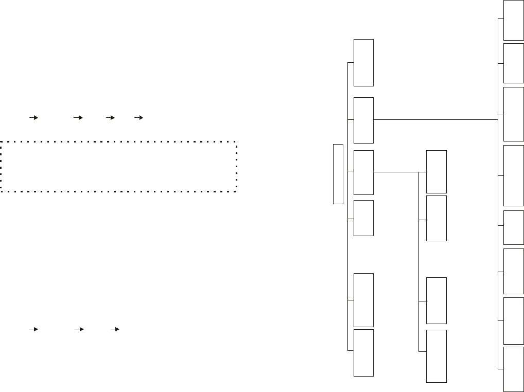
M ain M enu Function C hart
MAI
N
MENU
Add
*
Number
*
Name
*
Hi
gh
*
Low
*
Vi
brat
e
*Tone
*
Pul
se
*8
seconds
*
On
*
Of
f
*
Par
am
*
DI
R
*
CI
D
*
Rec
Cal
l
s
Base
1-4
*
Adj
ust
1-16
*
YES
*
NO
*
Ri
ng
1
*
Ri
ng
2
*
Ri
ng
3
*
Ri
ng
4
*
Hi
gh
*
Low
*
Of
f
*
Tone
1
*
Tone
2
*
Tone
3
*
Tone
4
Opt
i
on
*
Edi
t
*
Cl
ear
Ent
ry
*
Vi
ew
Number
Vi
ew
*
Ti
me
*
Name
*
Del
et
e
1.
Regi
st
er
2.
Der
egi
st
er
3.
Reset
Base
4.
Reset
Hand
*
Lock
*
Unl
ock
1
Ar
ea
code
1
Ri
ng
Vol
ume
2
DI
RECTORY
2
Tone/
Pul
se
2
Ri
ng
Type
3
Cal
l
er
I
D
3
Backl
i
ght
3
Key
Vol
ume
4
SOUNDS
4
Reset
4
Key
Tone
5
SETTI
NGS
5
Cust
om
name
6
REGI
STER
1
Key
Guar
d
6
Cal
l
Manager
7
Cont
r
ast
8
Di
al
Pr
ef
i
x
~37~
H andset / B ase R egis tra tion
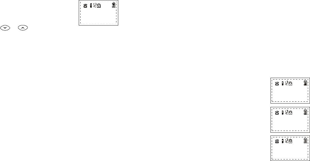
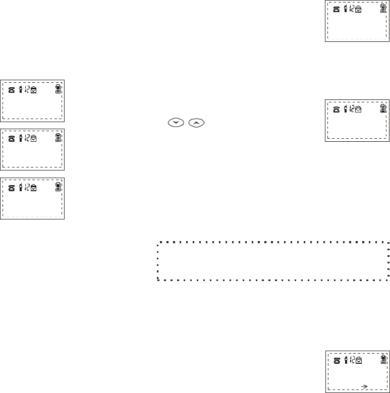
When th e handset is in the IDLE mode,
or w hen a call is on hold, th e Main
Menu can b e accessed by pressing
the RIG H T SO FT FU N C TION key.
Once in th e main m enu, a list of
available options w ill be displayed ,
two m enu options at a time as show n:
1. Use th e or scrolling keys
to view all of the m enu options.
2. At any time while in the M ain M enu,
an option can be selected by using
th e corresponding num ber fro m the
keypad.
Your handset(s), if purchased as a system , is pre-registered at the
fa c to ry and d oes not need to be re -re g istered to the base unit
purchased with the handset. Additional handset displaying "0 0 "
as their handset ID m ust be registered to the base unit. C harge
the handset battery fully before registering.
1. Plug in the base unit to AC pow er and place a fully charg ed
battery pack into th e new handset.
2. Verify base unit's pow er light is on and tu rn on th e handset
p ow er by pressing and holding th e E N D key for 2 seconds.
M ain M enu O ptions
Registration
Handset Registration
Main M enu:
1:KEY GUARD
2:DIRECTORY
¡õ¡ô
3:CALLER ID
4:SOUNDS
5:SETTIN G S
6:REGISTER
~38~
3. Place base unit into REG ISTR ATIO N m ode by p ressing and
holding th e and buttons at the sam e time
until you hear a single beep (about 3 seconds). The red "In-
Use" light will com e on. H and set re g istra tion m ust be
pe form ed with in 30 seconds afte r e n tering th e regis tra tion
m ode.
4. P ressing the RIG H T SO FT key, on the handset, selects th e
fu n c tion.
5. P ress the num b er " " key on th e handset keypad, this will
place the handset into the re g istra tion m enu.
6. P ress the num b er " " ke y on the handset keyp ad , th is
com pletes th e handset re g istra tion.
7. Repeat step s 3 through 6 for each handset you w ant to
register to th a t base.
8. The re s u lt of th e regis tra tion or deregistration procedure is
displayed on the LC D for 5 seconds. There are 4 possible
results:
* Registra tion is successful.
* Faile d re g istra tion or deregistra tion.
B ase failed to respond to handset.
Steps m ust be repeated to retry
procedure.
* B ase has already registered
maximum number of handsets (9 )
it can support. A handset must
be deregistered before a new
one can be added to the system .
VO LU M E PA G E
MENU
6
1
r
N o connection
Tab le full
Reg O K
New ID = X
~40~
4. Press the LEFT SO FT FUNC TION
key fo r "."
5. D eregistration is successful.
YES
The handset has now been de-registere d
fro m all base units . The handset ID num ber
will b e reset to "00" as seen in th e middle
of the top LC D line.
D ereg from
all bases
Register a Second, Third or Fourth Base U nit
A handset can be registered to a m aximum of 4
base units. All b ase units that com e fro m the factory are
registered as base unit 01.
NOTE:
If there is m o re than one b ase unit and a handset
is to be registered to m o re than one base unit, the base
unit's identification num ber m ust be changed fro m factory
default num ber of "1 " to either "2 ", "3 ", or "4 ".
NOTE:
1. Plug in the new base unit to AC pow er and place a fully
charged battery pack into the handset.
2. Verify base unit's power light is on and turn on the handset
pow er by pressing and holding th e END key fo r 2 second s.
~39~
U pon successful registra tion, your handset will
display "Reg OK New ID = "
Your handset will autom atically exit the
REG ISTRATION mode after 30 seconds.
You can re g ister your handset to a maximum of 4
base units. The handset ID num ber in th e middle
of the top line of the handset display will not
change after registering the firs t base unit
(kno w n as the primary base unit).
NOTE 1:
NOTE 2:
NOTE 3:
SECURITY FUNCTION:
MENU 6 3
A third o p tion is availab le for
deregistering all th e hand sets at once and generating a
new
base
ID
cod e
(system
registration
re s e t).
This
option
can
be
selected
by
pressing
"",
"",
"",
then
enter
a
new
base
num ber
(1 -4 ).
B o th the handset
and
base
must
be
in
the
registration
mode.
De-Registering a H andset fro m all B a s e U n its
1. Press the RIGHT SO FT FUNC TION key to select .
2. Press the " " key to select th e REGISTER option.
3. Press the " " key to select
RESET HAND. The LC D will
display the follow ing screen:
MENU
6
4
D e re g fro m
all bases?
YES N O
* Handset re g istered to a base with sam e ID.
9. Press EN D to re turn to th e handset main m enu.
ID Conflic t
B a se X
~ 42~
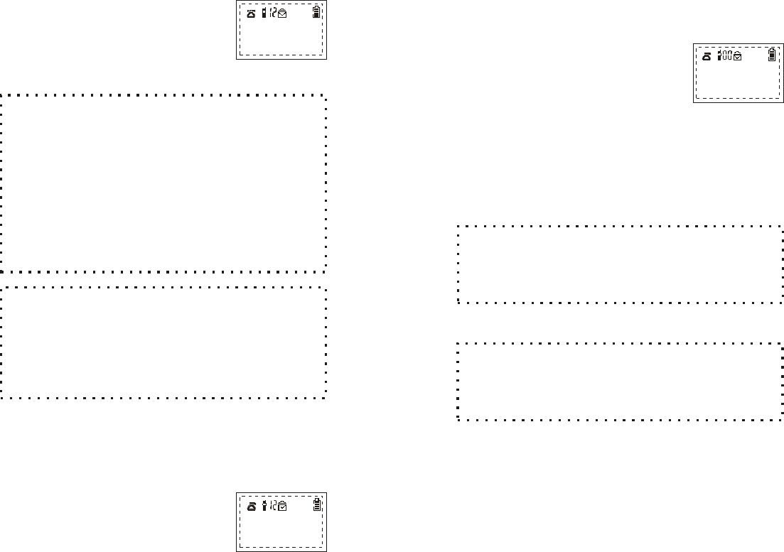
H andset M enu O ptions
Directory
K ey G uard
P ress "M ENU", "1 " to set KEY G UARD.
1. To access the KEY G UARD option fro m the IDLE made, press
th e RIGHT SO FT FUNCTION key to select the MENU option.
2. While in the M AIN MENU press th e
"1 " key to select KEY G UARD:
3. Selecting the KEY GUARD option
LOCKS the keypad from use. The
screen w ill display the follow ing:
4. To unlock th e keypad press the
LEFT SO FT FUNCTION key. The
screen w ill display the follow ing:
5. P ress the "1" key to confirm u n locking
th e keypad.
This fe a tu re allow s you to store up to 30 frequently used
telephone num bers (up to 20 digits each) and nam es (up to 14
characters each) in a directory that re s ides in th e handset
memory. Entries in the Phone D ire c to ry may be view ed or edited
at any time. The Phone Dire c tory m ay be view ed by pressing th e
or a rro w keys fro m the idle mode.
U nlock
Main M enu:
1:KEY GUARD
2:DIRECTORY
¡õ¡ô
3:CALLER ID
4:SOUNDS
5:SETTIN G S
6:REGISTER
Keypad
Locked
Press 1 to
confirm
UNLOCK
~ 41~
5. P ress the num ber " " button on
th e handset keypad, this w ill
place the handset into th e
regis tra tion m enu.
6. P ress the num ber " " button on
th e handset keypad.
7. The handset Display will now
request that you "Enter base ID
(1 -4 ): X"
8. Enter a num ber
fro m the keypad. C hoose a
b ase ID num ber diffe re n t fro m
b ase ID num ber you are already
using.
9. Repeat step s 1 through 8 for
each new base you want to
register.
3. Place base unit into REGISTRATION m ode by pressing and
holding th e and buttons at the sam e time
until you hear a single beep (a b o u t 3 seconds).
The red "In-U se" light will com e on. H andset registra tion must
be preform ed within 30 seconds after e n te ring the re g istration
Mode.
4. P ressing the RIG H T SO FT BUTTON, on the handset, selects
th e function.
VO LU M E PA G E
MENU
6
3
"1 ", "2 ", "3 ", o r
"4 "
E n ter b a se
ID (1 -4 ): X
Reg M enu
1. Register
2. D eregister
3. R eset B ase
4. Reset Hand
NOTE:
U pon successfully changing the base ID num ber,
the display will say "Base ID = X, D ereg All." This m eans
that you have successfully created a new identification
num ber for that base unit. All handsets p reviously
re g istered to that b ase unit (if any) w e re d e -re g istered. You
may now begin reg istering handsets to the base unit.
Follow steps 3 th roug h 6 of H andset R egistration section.
~44~
DIRECTORY EDIT MODE
While in th e DIRECTO RY VIEW m ode,
the LC D will disp lay th e fo llow ing screen:
To e n ter th e DIRECTORY EDIT mode,
either ADD or OPTION m ust be selected.
* If there are available sp aces, the firs t
em pty sp ace w ill be accessed
autom atically and the follow ing
screen will appear:
* If inform ation is to be stored in a
specific location, use th e
scrolling keys to find th e corre c t
location for th e new inform ation.
The location num ber will appear as
a 2 digit num ber to th e left of the
batte ry icon.
AD D
* Press the LEFT SO FT FUNC TION
key to select ADD. This choice will
allow an entry to be added to the
Phone Dire c to ry.
* If the dire c to ry is full, th e fo llow ing
will be displayed on th e LCD:
* To re turn to th e DIRECTO RY VIEW
mode, press the LEFT SO FT
FU N C TION key.
M e m o r y fu ll
Quit
Jane D oe
5551212
ADD OPTION
N um ber?
SAVE D ELETE
~43~
2. While in the M ain M enu, p ress
th e "" key to select DIRECTO RY:
3. Inform ation in the Phone Dire c tory is
stored vertically, as show n in Table 1
below . The up and dow n a rro w keys
are used to move through th e dire c tory
re c o rd s .
2
Main M enu:
1:KEY GUARD
2:DIRECTORY
¡õ¡ô
3:CALLER ID
4:SOUNDS
5:SETTIN G S
6:REGISTER
N o te : Press the RIGHT SO FT BUTTO N and enter the Index
Code to dial the phone dire c to ry num ber.
Table 1
Inform ation
Index Code
01 Nam e #1
Te lephone # 1
02 Nam e #2
Te lephone # 2
30 N am e #30
Te lephone # 30
DIRECTORY VIEW M O DE
P ress "M ENU", "2 " to access D ire c tory screen
1. To view the D ire c to ry fro m th e IDLE
m ode, p ress th e RIGHT SO FT
FUNCTIO N ke y to select the
MENU option.
~45~
* Select ADD again using the LEFT
SO FT FUNCTION key. The follow ing
screen will then appear:
1.E n te r a n e w phone num ber
by pressing th e corresp ond ing
keypad num ber key once.
The fo llow ing characters
re q u ire a special key com b ination:
press th e # key two times
(# # ).
p ress th e # key th re e tim es
(# # # ).
Note:
Space:
D ash:
N um ber?
SAVE D ELE TE
The dire c tory will store a nam e and a phone
num ber, or just a phone num ber, but not a nam e by itself.
NOTE:
2. P ress the
key to SAVE the phone num ber.
To correct an incorrect entry, press
th e RIG H T SO FT FUNCTION key to
select the D E LE TE option. D ELETE
will delete one num ber at a time
fro m right to left.
3. A prom pt will appear to enter a nam e
th a t goes w ith the phone num ber.
The nam e field can be left blank by
selecting SAVE with the LEFT SO FT
FUNCTION key.
LEFT SO FT FU N C TION
OR
Nam e?
*=CAPS LO CK
SAVE D ELETE
~46~
NOTE:
In th e nam e editing m ode, as indicated on th e LCD
prom pt, all letters will autom atically b e en tered in th e upper
case. Since this is th e default setting, using th e * key will
then allow you to enter lower case lette rs . This function w ill
stay locked in the low er case mode until th e * key is
pressed again, or th e nam e edit m ode is te rm inated.
4. To e n te r th e letters of a nam e, p ress
th e corresponding keypad num ber
one or more times depending on
th e order to the characters on the
key. See Table 2 for a listing of
availab le chara c te rs that can be
used in th e nam e field.
For exam ple: p ress "2 " once for th e
lette r "A," tw ice fo r the letter "B," etc.
5. When th e nam e is entered correctly, press the LEFT SO FT
FUNCTIO N ke y to select SAVE. The new entry will be displayed
on th e screen and the D IRECTO RY VIEW m ode will
autom atically be activated .
NOTE:
Each time you enter a character, the cursor
autom atically advances to the next chara c te r field as long
as you p ress a diffe re n t keypad key to enter each character.
H ow ever, if you need to press a keypad key two o r m o re
times to enter consecutive characters, you need to firs t
press the key to ad vance the cursor to th e next
character field. Selecting DELETE with the RIGHT SO FT
BUTTON or p ressing the ke y w ill b acksp ace the
cursor to the previous field. The will ad vance th e
cursor.
~ 48~
OPTION
E d it O p tio n
C hoosing O PTION while in the D IRECTO RY EDIT m ode allow s a
dire c tory record to be edite d , deleted or a num ber to be view ed.
P ress key
to select OPTION. The follow ing screen
will be disp layed:
This option allow s a phone re c o rd to be changed.
RIG H T SO FT FUNCTION
1. Select th e "1 " key fro m th e keypad.
The fo llow ing screen w ill be
displayed :
2. Use th e RIGHT SO FT FUNCTION
key to delete th e phone num ber or
simply ty p e the new num ber over the
old e n try.
3. If a nam e is a part of the re c o rd , you
will re c e ive the follow ing prom pt:
O ptions
1:Edit
2:Clear Entry
¡õ¡ô
3:View N u m ber
5551212
SAVE D ELETE
JA N E D O E
* CAPS LO CK
SAVE D ELETE
~ 47~
Table 2
C haracters
Key
1'+ ,. * ( ) & 1
2A B C C 2
3D E F 3
G H I 4
4
5J K L 5
6M N O N 6
~
7P Q R S 7
T U V 8
8
9W X Y Z 9
00
*TOGGLES CASE
SPAC E -
#
Exam ple:
In the DIRECTORY EDIT mode, to enter th e nam e
"Jane Doe" use th e fo llow ing key sequence:
5 (J ) * 2 (a ) 6 6 (n ) 33 (e ) # (space) * 3 (D ) * 666 (o ) 33 (e )
NOTE:
Unique character Key 2: C, Key 6: N
~

~ 49~
5. Once th e new inform ation is entered,
press th e LEFT SO FT FU N C TION
key to save the new entry.
6. If the nam e is unchanged press th e
LEFT SO FT FU N C TION key to re -
save and exit to the DIRECTO RY
Selecting DELETE will move the cursor to the far
right edge of the LC D screen. Pressing th e RIGHT SO FT
FU N C TION key repeated ly will move th e cursor right to left
across the LC D screen, deleting each letter ab ove cursor.
NOTE:
4. The cursor w ill appear under th e firs t
lette r o f th e nam e. Typ e new
inform ation over the existing nam e
or p ress th e RIGHT SO FT
FUNCTION key to select D E LE TE .
JANE DOE
5551212
SAVE D ELETE
~ 50~
Clear E n try O p tio n
This option allow s a record to be com pletely rem oved fro m the
Phone Directory.
1. While in the O ptions M enu p ress th e
"2 " key to select clear e n try :
2. At this point, the record p reviously
accessed while in the DIRECTO RY
VIEW m ode can be deleted by
pressing the LEFT SO FT FUNCTION
key to select YES as show n on the
LCD screen:
3. Deleting the records will bring up
th e follow ing prom pt, at which time
a new record can be added to the
dire c tory (re fe r to steps und er AD D) :
4. Selecting NO will re turn the handset
to the DIRECTO RY VIEW mode.
Calle r ID
Caller ID inform ation will then appear on the LC D and also be
stored autom atically in the handset fo r later re trieval.
To use this option you m ust first subscribe to the C aller
ID service offered by your local telephone com pany.
O ptions
1:Edit
2:Clear Entry
3:View N u m ber
Confirm Clear
E n try ?
YES N o
ADD
Em pty
View O ption
This option allow a record to be view ed in the phone dire c to ry.

~51~
3. Press th e key to view th e
m ost recent call or the key
to v iew th e o ldest call in fo rm a tion:
4. The Caller ID log will store up to
three inform atio n fields:
* C alle r phone num ber, if transm itte d .
* C alle r nam e, if transm itted.
* D ate and time stamp.
5. The firs t Calle r ID screen will
display th e firs t tw o inform ational fields.
Press "M E N U ", "3 " to access Caller ID screen.
1. From th e ID L E m ode, press th e
LE FT SO FT FUNCTION key to
select MENU.
2. To access th e C a lle r ID in fo rm a tion
stored in th e handset, press th e
"3 " ke y fro m th e ke yp a d to select
Caller ID .
NOTE:
S how s the num ber of new Caller ID e n trie s
since the last time th e C a lle r ID log was checked . The
va lue in th e to p LCD lin e to the right of th e en velope
icon.
02 Newcalls
View :¡õ¡ô
7145551212
Nam e
Tim e D elete
Main M enu:
1:KEY GUARD
2:DIRECTORY
¡õ¡ô
3:CALLER ID
4:SOUNDS
5:SETTIN G S
6:REGISTER
NOTE:
Caller ID inform ation is stored in a table with
the new est e n try on th e to p o f th e table. Using th e
to v iew th e C a lle r ID lo g ensures starting at th e "to p " of
th e ta b le.
~52~
7. The displayed inform ation m ay be
deleted w ith th e RIGHT SO FT
FUNCTION key. The disp lay w ill
show :
8. P ress the LEFT SO FT FUNCTION
key to confirm th e deletion, or
p ress th e RIG H T SO FT FU N C TION
key to cancel th e com m and.
9.While in th e CALLER ID VIEW mode, the displayed num ber can
be dialed by pressing TALK.
10.P ress END to re turn to the Main M enu.
: Once the caller ID capacity (3 0 records) has been
reached, the oldest re c o rd is rem oved fro m th e ta b le.
NOTE
6. D ate and time inform ation can be
view ed by pressing th e L E F T
SO FT F U N C TIO N ke y:
The 2 digit num ber to the right of th e en velop e
icon tracks the num ber of unview ed C aller ID re c o rd s .
NOTE:
7145551212
09/02 11:12
Nam e Delete
Delete?
YES N O

~53~
To m ake use of this option you must sub scribe to both C all
Waiting and C aller ID service w ith y o u r local telephone com pany.
* W hen on a call, you will be alerte d to an incom ing call with a
short beep. The phone num ber and nam e of the incom ing
caller will be displayed simultaneously.
* You can place the firs t call on hold and answ er the second
call by pressing TALK. P ressing TA LK ag ain w ill sw itch back
to the firs t call.
C a lle r ID with C a ll W a iting O ption
Sound
P ress "M ENU", "4 ", "1" to access Ring
Volum e m enu.
1. From the IDLE m ode press the
RIGHT SO FT FUNCTION key to
e n te r the M ain M enu:
2. Select th e SOUNDS option by
p ressing the "4 " key fro m th e
keypad.
3. Select RING VO LUM E by p ressing
"1 ".
4. Once in this option, th e c u rre n t ring
volum e level will be displayed on the
second line of th e LCD:
R ing Volum e
Sound s M enu
1.R ing Volum e
2.Ring Type
3 .K ey Vo lum e
4 .K ey Vo lu m e Tone
Ring Volu m e
High
¡ô¡õ
SAVE
M ain M enu:
1:KEY GUAR D
2:DIRECTORY
¡õ¡ô
3:C A LLER ID
4:SOUNDS
5:SETTING S
6:REGISTER
~54~
5. Ring levels are : HIGH, LO W and
VIB RATE. U se the scrolling keys
to select ring level. Press the LEFT
SO FT FUNC TION key to SAVE
setting .
6. Selecting EN D re turns handset
to the Sounds M enu.
P ress "M ENU", "4 " , "2 " to access R ing Type m enu.
One of fo u r d istinctive ring tones may be selected for th e handset
by pressing the or scrolling keys and pressing the
LEFT SO FT BUTTON to save.
The key volum e is the loudness of the sound of th e ke ys w h en
pressed . C hoices are: HIGH, LO W and O FF.
The key tones are the typ e o f sound th a t the keys produce w hen
pressed . C hoices are To ne 1, To ne 2, Tone 3 and To ne 4.
R ing Type
Key Volum e
Key Tone
P ress "M ENU", "4 " , "3 " to access K ey Volum e m enu.
P ress "M ENU", "4 " , "4 " to access K ey Tone m enu.
S e ttings (Setting Handset Preferences)
This m enu option can be used to set: local area code, dial mode,
and the backlight. Selecting reset with in this option allow s you to
reset these preferences (p lus all sound settings) back to th e
fa c to ry settings. Custom Nam e is th e nam e that appears on th e
LC D in th e IDLE mode.
~55~
From the IDLE m ode, p ress th e
RIGHT SOFT FU N C TION key
to enter the Main Menu. P ress
the "5" key fro m th e ke yp ad to
select SETTINGS.
P ress "M ENU", "5 ", "1" to access A rea cod e screen.
By setting the local area cod e, when a
telephone num ber is a u to -d ialed fro m the
Phone Directory or Caller ID containing
the selected area code, th e phone will
not include the area cod e w hen the num ber
is dialed.
1. When th is option is selected, th e
local area cod e is displayed
as show n:
The field fo r the area code has
a maximum of three num bers.
2. The area code can be edite d by ty p ing
th e new num bers over the current digits .
The key can be used to delete
th e num ber above th e cursor and the
K ey can be used to m ove to th e
d esired num b er.
3. P ress the key
to save the new area code setting or
p ress END to return to the Settings
M enu w ithout saving th e num ber.
*
Area Code
LEFT SO FT FU N C TION
Setting M enu
1:A rea code
2:Tone/P ulse
¡õ¡ô
3:Backlight
4:Reset
5:C ustom nam e
6:C all M anager
7:Contrast
8:Dial Prefix
M ove cu rso r:
714
¡õ¡ô
M ain M enu:
1:KEY GUAR D
2:DIRECTORY
¡õ¡ô
3:C A LLER ID
4:SOUNDS
5:SETTING S
6:REGISTER
~56~
Tone/P ulse Mode
B acklight
P ress "M ENU", "5 ", "2" to access Tone/Pulse s c re e n .
The handset m ay be set to either tone or pulse mode.
1. Afte r s e lecting th is option, th e LCD
will show th e c u rre n t setting as
show n:
Use th e scrolling keys to
change the setting.
2. P ress the LEFT SO FT FUNCTION
key to save the new dial m ode or
p ress END to return to the Settings
M enu w ithout saving.
P ress "M ENU", "5 ", "3" to access Backlight screen.
The length of time the backlight sta ys lit w hen the handset is in
use m ay b e set with three options: 8 sec, Off and On.
1. The scrolling keys m ay
be used to choose one of the three
options.
2. P ress the LEFT SO FT FUNCTION
key to save the new backlight setting
or p ress EN D to re tu rn to the
Setting s Menu without saving .
: It is recom m ended that the backlight be kept at th e
fa c to ry setting of 8 seconds. Leaving the backlight on will
deplete th e battery life more quickly.
NOTE
Dial M ode"
Tone
¡õ¡ô
SAVE
8 Sec
SAVE
~ 57~
Reset
C ustom Nam e
P ress "M ENU", "5 ", "4 " to access R eset m enu.
C hoosing this option allow s th e handset param eters (d ial mode,
backlight, ring and key tone settings and ring/voice vo lum e) to be
re s e t to th e fa c tory settings. Also, this option
will delete all th e Phone Dire c tory e n tries and all th e Caller ID
e n tries.
1. The R eset param eters option LC D
will show :
2. The R eset DIR option LC D will show :
3. The CID option LCD will
show :
4. In all cases, press the LEFT
SO FT FUNC TION key to
select YES and the RIGHT
SO FT FUNC TION key to
select NO.
5. C hoosing YES, NO or th e END key
will re tu rn th e handset to the Settings
M enu.
P ress "M ENU", "5 ", "5 " to access C ustom nam e screen.
This option allow s either a nam e or a greeting to be selected th a t
will be disp layed on the LCD in ID LE m ode or when th e handset
is turned on.
Factory Set?
YES N O
D e le te a ll
D IR entries
YES N O
D e le te a ll
CID entries
YES N O
~ 58~
C all M anager
P ress "M ENU", "5 ", "6 " to access C all M anager screen.
This option allow s the handset to re c e ive
calls fro m 1 to 4 base units.
1. O nce in the Settings M enu press the
"6 " key fro m th e keypad to select the
Call M anager option. The screen
will disp lay:
1. A ccessing this option displays the
c u rre n t nam e setting.
2. The custom name can th e n be
edited by using the num bered
keys on th e keyp ad to overw rite
th e existing characters.
3. In this option the second and th ird
lines of the LC D can be used. The
keys can be used to
move the cursor fro m one line to the
other and fro m one side of th e line
to the other.
4. Use LEFT SO FT FUNCTION key to
save th e new custom nam e or th e
RIGHT SO FT FUNCTIO N key to
delete th e nam e. EN D will return
th e handset to the Settings M enu.
This p roced ure is similar to the phone dire c to ry
nam e edit mode (see Table 2: Availab le C haracters und er
Dire c tory O ption).
NOTE:
EnGenius
=C aps lock
*
SAVE D elete
EnGenius
SN-920
SAVE D elete
Receiv e C a lls
from base 1:
¡õ¡ô
¡õ¡ô
S A V E Yes N o

~ 60~
D ial P refix
P ress "M enu", "5", "8" to access th e Dial Prefix screen.
Allow s you to enter up to an eight-d igit dialing prefix (i.e.:
1010555 fo r long distance service).
Use the UP/DOW N scrolling keys to toggle betw een th e Yes or
No Dial Prefix default selection. P ress the RING SO FT FUNCTION
key to select "E d it" then enter th e Dial Prefix num b er via th e
keypad. P ress th e LEFT SO FT FUNCTION key to select "Save".
If you have elected to use a Dial Prefix, e n te r a phone num ber,
prior establishing dial tone, then press th e " TA LK " Key. The
screen will ask you "U se Prefix?" select "Yes" by pressing th e LEFT
SO FT FUNCTIO N key or select "No" by p ressing the RIGHT SO FT
FU N C TION key.
~ 59~
2. The scrolling keys may
be used to select a b ase unit num ber
fro m 1 to 4. P ressing the RIG H T SO FT
FUNCTIO N key m oves the fro m
YES to N O and back to YES in th e
selection process.
P ressing the LEFT SO FT FU N C TION
key will save the setting.
3. Repeat th e process until all b ase units
fro m which calls are to be accepted
have been selected for th e handset.
P ress "M ENU", "5 ", "7 " to access C ontra s t screen.
This option adjusts the contra s t
for the handset's LC D screen.
1. While in the Settings M enu, select
th e "" key fro m the keypad. The
LCD will disp lay th e c u rre n t contra s t
setting :
2. Use th e scrolling keys to
change the contra s t se tting fro m 1 to
1 6 (1 is th e lightest se tting and 16 is
darkest).
3. The LEFT SO FT FUNCTION key will
save th e new setting. P ress EN D to
re turn the handset to th e Setting s
M enu. P ressing E N D ag ain returns
th e handset to the M ain M enu.
C ontrast
7
Contrast:12
Adjust=¡õ¡ô
SAVE

~ 61~
Base
Uni
t
902-928
Mhz
AC
Adapt
er
900
mW
Yes
32
kbps
ADPCM
93
kbps
142
Pul
se-shaped
FSK
Ti
me
Di
vi
si
on
Dupl
ex
(TDD)
Fr
equency
Hoppi
ng
CDMA
>
200
per
second
<
-106
dBm
(@
BER
10)
-
2
2
dBi
I
ndoor/
5
dBi
Out
door
TI
A/
EI
A-470B
Yes
FCC
Part
15,
Part
68
CAN/DOC
RSS210,
CS03
CUL
1950,
UL
1950
FCC
MPE
6
7/
8
x
5
x
1
5/8
i
nches
172
x
124
x
41
mm
18
ounces/497
grams
El
ectr
i
cal
Speci
f
i
cat
i
ons
Frequency
Power
Source
Output
Power
Transmi
t
Power
Cont
rol
Speech
Codi
ng
User
Dat
a
Rat
e
Number
of
Channel
s
Modul
at
i
on
Dupl
ex
Mul
t
i
pl
e
Access
Fr
equency
Hoppi
ng
Rat
e
Recei
ver
Sensi
t
i
vi
t
y
Ant
enna
Gai
n
Voi
ce
Qual
i
ty
Li
ne
Rever
sal
Support
Regul
ati
on
Compl
i
ance
Saf
et
y
Compl
i
ance
Di
mensi
ons
wi
t
hout
Antenna
Wei
ght
Por
tabl
e
Handset
902-928
MHz
750
mAh
Ni
MH
630
mW
Yes
32
kbps
ADPCM
93
kbps
142
Pul
se-shaped
FSK
Ti
me
Di
vi
si
on
Dupl
ex
(TDD)
Frequency
Hoppi
ng
CDMA
>
200
per
second
<
-106
dBm
(@
BER
10)
-2
Max
1.
5dBi
,
Typi
cal
0
dBi
/
Ret
ract
abl
e
Max
3dBi
,
Typi
cal
2
dBi
/
Fi
xed
TI
A/
EI
A-470B
NA
FCC
Par
t
15,
Part
68
CAN/
DOC
RSS210,
CS03
Hear
i
ng
Ai
d
Compat
i
bl
e
CUL
1950,
UL
1950
FCC
SAR
(OET-65)
7/8
x
1
3/8
x
5
1/4
i
nches
46
x
34
x
132
mm
Wi
t
h
Batt
ery:
9
ounces
250
gr
ams4
ounces
Char
ger
NA
AC
Adapter
NA
NA
NA
NA
NA
NA
NA
NA
NA
NA
NA
NA
NA
CUL
1950,
UL
1950
3
1/2
x
4
1/8
x
2
1/4
86
x
104
x
56
mm
4
ounces
115
grams
Not
e:
The
manuf
act
urer
r
eserves
t
he
ri
ght
t
o
change
desi
gns
and
speci
f
i
cat
i
ons
wi
t
hout
not
i
ce.
Product Specifications
~ 62~
C o rd le s s S a fe ty Tips
Your cordless phone give s you the freedom and flexibility to stay
in touch while you m ove around. H ow ever, th e safe and
responsible use of th e phone depends entire ly on you. Avoid
accidents by not reaching fo r the phone or talking on the phone if
that distracts you fro m w o rk ing safely. Your life and th e lives of
others are at stake.
1. When using your cordless phone ensure your safety an d the
safety of others:
Always watch where you are walking and standing.
Don't let a phone call distra c t you from working safely.
2. In an Em ergency
If an em ergency occurs, dial 911. Remember: if you are in an
area w here your phone is searching or scanning for a signal or
th e re is no signal, it is h ighly probable that a call to 911 will not
go through. Locate the nearest landline phone and call for
help.
Cordless 911 calls may not autom atically provide em erg ency
personnel with y o u r nam e, phone num ber or location. Te ll the
dispatcher:
Your nam e and phone num ber, including area code.
The nature of the em ergency.
W hether police, fire o r m edical assistance is needed.
The exact location of the em erg ency, including cross streets,
mileposts or landm arks.
BEFO RE USIN G YO U R TE LE P H O N E EQ UIPM ENT, BASIC
SAFETY INSTRUCTIONS SHO ULD ALW AYS BE FO LLO W ED TO
RED UCE TH E RISK OF FIRE, ELECTRIC SHO CK AN D INJURY
TO PERSO NS AND DAMAGE TO PRO PERTY.
Im portant Safety Instructions

~ 63~
3. Power Outage
In the event of a pow er outage, your cordless te lephone will
not allow you to m ake an outgoing call or take an incom ing call.
The cordless base station require s electricity fo r operation.
You should have a telephone which does not require electricity
availab le for use during pow er outages, or alte rn a tively ha ving
p rop er backup power for the base station.
4. Notice to Hearing Aid W earers: This phone system is
com patible with inductively coupled hearing aids.
5. Notice to Cardiac Pacem aker W earers: Preliminary studies
done by FD A and others have show n th a t, although
interference to the implanted cardiac p acem aker may occur
w hen operating very closely, wire less te lephones "do not seem
to pose a significant problem for p acem aker w earers."
H ow ever, until more is know n, FD A sug gests that people with
p acem akers m ay w ant to take p recautions w hen using or
c a rry ing a wire less te lephone to ensure th a t there is am ple
distance betw een the telephone and th e p acem aker.
1. R ead and understand all instru c tions.
2. Follow all w a rn ing s and instru c tions includ ing those m arked
on th e product.
3. U nplug th is product fro m th e wall telephone jack and power
outlet before cleaning . Do not use liquid cleaners or aerosol
cle a n e rs . Use dam p cloth fo r cleaning.
4. D o n o t use the telephone near water, for exam ple, near a
b a th tu b , w ashbow l, kitchen sink, laundry tu b , wet basem ent
or sw imming pool.
Product Safety Tips
5. D o n o t place this product on an unstable c a rt, stand or table.
The product may fall, causing serious dam ag e to the product.
~ 64~
6. Slots or openings in the product's housing back, side and
bottom , are provided for ventilation. These openings must not
be blocked or covered. Placing th e product on a bed,
carpeting , or other similar surface m ay block these opening
and should be avoided. This product should never be placed
near or over a ra d iator or heat register. This product sho uld not
be placed in a built-in installation unless proper ventilation is
p rovided.
7. This product should be operated only fro m the type of power
source indicated on th e marking label. If you are not sure of
th e type of pow er supply to your hom e, consult your dealer or
local p ow er com p any.
8. D o n o t overload wall o u tlets and extension cord s as this can
result in th e risk of fire or electric shock.
9. N ever push objects of any kind into this product through
housing slots as they m ay touch dangerous volta g e p o ints or
short out parts that could re s u lt in th e risk of fire , electric shock,
or injury. N ever spill liquid of any kind on th is product.
10. To reduce th e risk of electric shock or burns, do not
disassem ble th is product. Take this product to qualified
service personnel w hen service or repair w o rk is required.
O pening or re m o v ing covers may expose you to dangerous
voltag es, electrical c u rre n t or other risks. Incorrect
reassem bling of th e product can cause electric shock w hen
th e product is subsequently used.
11. W a rn ing: C hanges or m odifications to this product n o t
expressly approved by EnG enius could vo id th e w a rra n ty a n d
the FC C authorization to operate the eq uipm ent.
12. U nplug the base station fro m th e wall outlet and refer
servicing to qualified service personnel under th e fo llow ing
conditions:
If liquid had been spilled into the product.
When th e power supply cord or plug is dam aged or frayed.
If the product has been exposed to ra in or water.
„h
„h
„h

~ 65~
If th e product does not operate norm ally by fo llow ing th e
operating in s tru c tions. Adjust only those contro ls that are
covered by th e operating instru c tions because im proper
ad justment of other controls m ay result in dam age and will
often re q u ire e x te n s ive w ork by qualified service personnel
to re s tore the product to norm al operations.
If th e product has been dropped or housing has been
dam aged.
If th e product exhibits a distinct change in p e rfo rm a n c e .
13. Avoid using te lephone during an ele c trical storm . There m ay
be a risk of electrical shock fro m lightning.
14. Do not use th e te lephone to re p o rt a gas leak while in the
vicinity o f the leak.
15. The antenna on the desk station d oes not re tra c t. To prevent
injury, do not place the telep ho ne w here persons can step,
trip or fa ll on th e te lephone.
16. Do not place metal objects on th e antenna.
17. Do not install the base station or cord less handset charger
near microw ave ovens, ra d io equipm ent, or non-cable
connected televisions. These appliances may cause electrical
interference to the base station or cordless handset.
18. The base station must be placed on a hard, flat s u rfa c e a n d
connected to both a phone wall jack and an AC pow er outlet.
19. Do not stick foreign objects into any of th e holes on th e base
station or c o rd less handset. You could harm the speakers,
e a rp ieces, microphones, or yourself.
20. Batte ry S a fe ty Precautions: To reduce th e risk of fire , injury or
electric shock, or property dam ag e, and to properly dispose
of batteries, please read and und erstand th e fo llow ing
instru c tions:
BATTERY M UST BE RECYCLED OR DISPO SED OF
PRO PERLY. DO NO T DISPO SE B ATTER Y IN M UNICIPAL
W ASTE.
~ 66~
Only use EnG enius approved N ickel-M etal Hydrid e (N iMH)
rechargeable batte ries in th e c o rd less handset and battery
charg er.
DO NOT use other rechargeable batte ries or non-
rechargeable batte ries, or mixed types of batte ries. The
batteries could short-c irc u it, and th e battery shell may be
dam aged causing a hazard ous condition. In s tru c tion lab els
are located in th e handset and charging unit battery
com partm ent.
Alw ays follow b asic safety precautions w hen using and
disp osing of batte ries. D o n o t dispose of th e batteries in a
fire ; the cells m ay exp lode. Do not expose batteries to water.
Check with local codes for special disposal instru c tions.
Periodically clean the charge contacts on both the charg er
and handset.
DO NOT mix old and new batte ries in this product.
Position positiv e (+ ) b a ttery contact to m atch diagram in
c o rd less handset.
Charge the batteries provided w ith , or identified for use with ,
this product only in accord ance with th e in s tru c tions and
limita tions specified in the instru c tion m anual.
Exercise care in handling batteries in order not to short the
batteries with conducting m aterials such as rings, bracelets,
and keys. The batteries or conducting m aterial m ay
overheat and cause burns or fire .
Do not open or mutilate the batte ries. Released ele c tro lyte
is c o rro s ive and m ay cause dam age to the eyes or skin.
the ele c tro lyte may be toxic if sw allow ed.
D u ring charging , batteries heat up. This is norm al and is not
dangerous.
Do not use non-EnG enius charging devices. This could
dam age the batte ries.
SAVE TH ESE SAFETY INSTRUCTIONS

~ 68~
6. This telephone system equipm ent has been tested and found
to com ply with the limits for C lass B digital device, pursuant to
Part 15 of the FCC Rules and RS210 of the DOC Rules. These
limits are designed to provide reasonable protection against
harm ful interference in a residential installation. Som e cord less
and wire less te lephones operate at freq uencies th a t m ay cause
interference to nearby TV's, VCR's, radio, com puters, or other
electronic devices. To minimize or prevent such interference,
th e te lephone system should not be placed or operated near
these devices. If interference is experienced, moving the base
station or handset farther aw ay fro m them will often reduce or
eliminate the interference.
7. H ow ever, th e re is no guarantee that interfe re n c e w ill not occur
in a p a rticular installation. If th is telephone system d oes cause
harm ful interference to other electronic devices, which can be
determ ined by turning th e system off and on, the user is
encouraged to try to correct the interference by one or more of
th e follow ing m easures:
Increase th e separation between the handset and/or base
and the device that experiences interference.
C onnect the base station into a pow er outlet on a circ u it
different fro m th a t to which the other device is connected.
or, connect the base station to another te lephone outlet.
C onsult th e dealer or a n e x p e rienced ele c tro n ic technician
for help.
1. This telephone system com plies with Part 68 of the FC C ru les.
On th e bottom of the base station is a label that contains,
am ong other inform ation, the FC C Regis tra tion Num ber, Ringer
Equivalence N um ber (REN ) and the Universal Service O rder
C o d e (U S O C ), which is RJ-11C . Your te lephone com pany m ay
ask you fo r this inform ation.
2. The REN is useful to d e te rm ine th e quantity o f d evices you
m ay connect to your telephone line and still have all of those
d evices ring w hen your telephone num ber is called. In m ost,
but n o t all areas, the sum of the REN's of all devices connected
to one line should not exceed five (5 .0 ). To be certain of the
num ber of devices you m ay connect to your line, a s d e te rm ined
by the REN , you should contact your local te lephone com pany
to determ ine the m aximum REN for your calling area.
3. If your telephone equipm ent causes harm to th e te lep hone
netw ork, the telephone com p any m ay ask you to disco nnect
the system fro m th e line until th e problem has been corrected
or th e y m a y disco ntinue your service te m p o ra rily. If possible,
they will n o tify you in advance. But if advance notice isn't
practical, you should be notified as soon as possible. You will
be inform ed of your right to file a com p laint with FC C or DOC.
4. Your telephone com pany may m ake changes in its facilities,
equipm ent, operations, or procedures that could affe c t th e
proper functioning of your telephone system . If th e y do and if
possible you w ill be notified in advance to give you an
opportunity to maintain uninte rru p ted te lephone service. If you
experience trouble with this telephone system , disconnect it
fro m th e netw ork until the problem has been corrected or until
you are s u re that the equipm ent is not malfunctioning.
5. This telephone system may not be used on coin service
provided by the telephone com pany. C onnection to party lines
is sub ject to state tariffs. Privacy of com m unications m ay not
be ensured w hen using th is phone.
~ 67~
Regulatory In fo rm a tio n
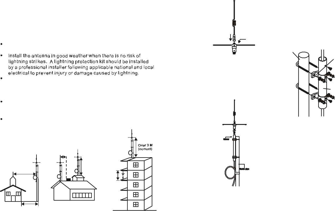
whip x 6
EnGenius Optional Outdoor Antenna
lnstallation lnstructions
TM
For safet
y
and o
p
timum
p
erformance
,
be sure to read these
instructions carefully.
Order lnformation
Please order the EnGenius SN-900 Ultre Outdoor Antenna and/or
cable.
Warning
For
y
our safet
y,
kee
p
the antenna awa
y
from electric
p
ower lines to
avoid electric shock.
TM
For FCC compliance, the outdoor antenna must not be located
within 8 inches (20cm) of any person.
Site Selection
The higher the antenna is installed, the better the communication
will be. lf you can install the antenna higher than surrounding
obstructions, the communication range will be better.
The antenna must be on the roof and maintain a three meter
(10 feet) clearance in all directions to meet RF safety requirements.
A
ntenna
l
nsta
ll
at
i
on
1. Find a mast
(
metal
p
ole
)
that is lon
g
er than five meters and 25 to
50mm (1"to 1.9") in diameter.
2. Assemble the antenna body and six whips.
3. Connect brackets to guide
pipe, sliding the brackets on
from the bottom.
4. Fit the guide pipe and
bracket on mast firmly.
5. Thread the coaxial cable
through the guide pipe and
connect one end of the
coaxial cable to the antenna.
6. Connect the other end of
the coaxial cable to the base
station.
Note:Use only EnGenius antenna and cable. The base
station antenna connector has reverse thead that
only works with cables supplied by EnGenius.
Over 3 M (correct)
Over 3 M
(correct)
Over 3 M
(correct)
Less than 3 M
(incorrect)
Less than 3 M
(incorrect)
Bracket
Guide pipe
Mast
Antenna

When using EnGenius SN-900 Ultra, always follow basic safety
precautions to reduce the risk of injury, fire, and electical shock,
including the following practices:
1. Read and understand all instuctions
2. Avoid using a telephone during thunderstorms.
3. Do not use a telephone in the vicinity of a gas leak.
4. Do not use this product near water, or when you are wet.
5. Unplug this product form any line or power source before
cleaning or if it comes in contact with any liguids.
6. Install this product in a protected location
7. This product should be operated only from the type of power
source indicated on the marking label.
included in the user's
manual and this antenna installation instructructions. ln anddition,
observe all warnings and instructions marked on the product.
There may be a
remote chance of electrical shock from lightning.
Report a suspected gas leak immediately, but use a telephone
away from the area where gas may be leaking. Because this
product is a wireless model, make sure the base is also removed
form the area.
For example, do not use it in a wet basement or shower, or next to a
swimming pool, bathtub, kitchen sink, or laundry tub.
Do not use liquids or aerosol sprays for cleaning. Use only a damp
cloth when cleaning. Do not plug the product back in until it has
dried thoroughly.
where it is not at risk
of falling and no one can trip over and line or power cord. Protect
cords from damage or fraying. Do not place and objects on the
power cord.
lf you are not sure of the type of power supplied to your home,
consult your dealer or local Power Company. lf this product has
user replaceable betteries, replace batteries only as described in
your user's manual. Do not burn or puncture batteries because
they contain caustic chemicals.
8. Do not short circuit the battery pack.
9. Do not block slots and openings in the cabinet and the back or
bottom, these are provided for ventilation.
10.Never push objects of and kind into this product through
cabinet slots
11.To reduce the risk of electrical shock, do not disassemble this
product.
12.Do not overload wall outlets and extension cords as this can
result in the risk of fire or electrical shock.
13.Unplug this product from the wall outlet if any of the following
situations should occur:
The metal bands on the
battery pack should never come in contact with a conductive
surface at the same time. Also, do not let two battery metal bands
touch each other.
To protect it from
overheating, do not block these openings by placing the product on
the bed, sofa, rug, or other similar surfaces. This product should
never be placed near or over or over a radiator or exceed
environmental specifications listed in the user's manual. In
addition, this product should not be placed in a built-in installation
where proper ventilation is not available.
as they may touch dangerous voltage points or short
out parts that could result in a risk of fire or electrical shock.
lf service or repair work is required, contact EnGenius
Customer Service or email us at
info@engeniustech.com. Opening or removing cadinet parts other
than s
p
ecified access doors ma
y
ex
p
ose
y
ou to dan
g
erous volta
g
e
s
or other risks. Lncorrect reassembling can cause electrical
shock when the appliance is subsequently used.
when the power supply cord or plug is damaged or frayed.
lf liquid has been spilled into the product.
lf
the
the product has been exposed to rain or water.
lf the product does not operate normally by following the operating
instructios. Adjust only those controls that are covered by the
operating instructions.
lf the product has been dropped and the cabinet has been
damaged.
lf the product exhibits a distinct change in performance.
TM
SAVE THESE INSTRUCTIONS