Senao Networks AP8120-O Wireless Access Point User Manual
Senao Networks, Inc. Wireless Access Point
UserManual.wiki
>
Senao Networks
>
AP8120 O User Manual
User Manual
Navigation menu
Upload a User Manual
Namespaces
Wiki Guide
HTML
PDF
Info
Views
User Manual
Discussion / Help
Navigation
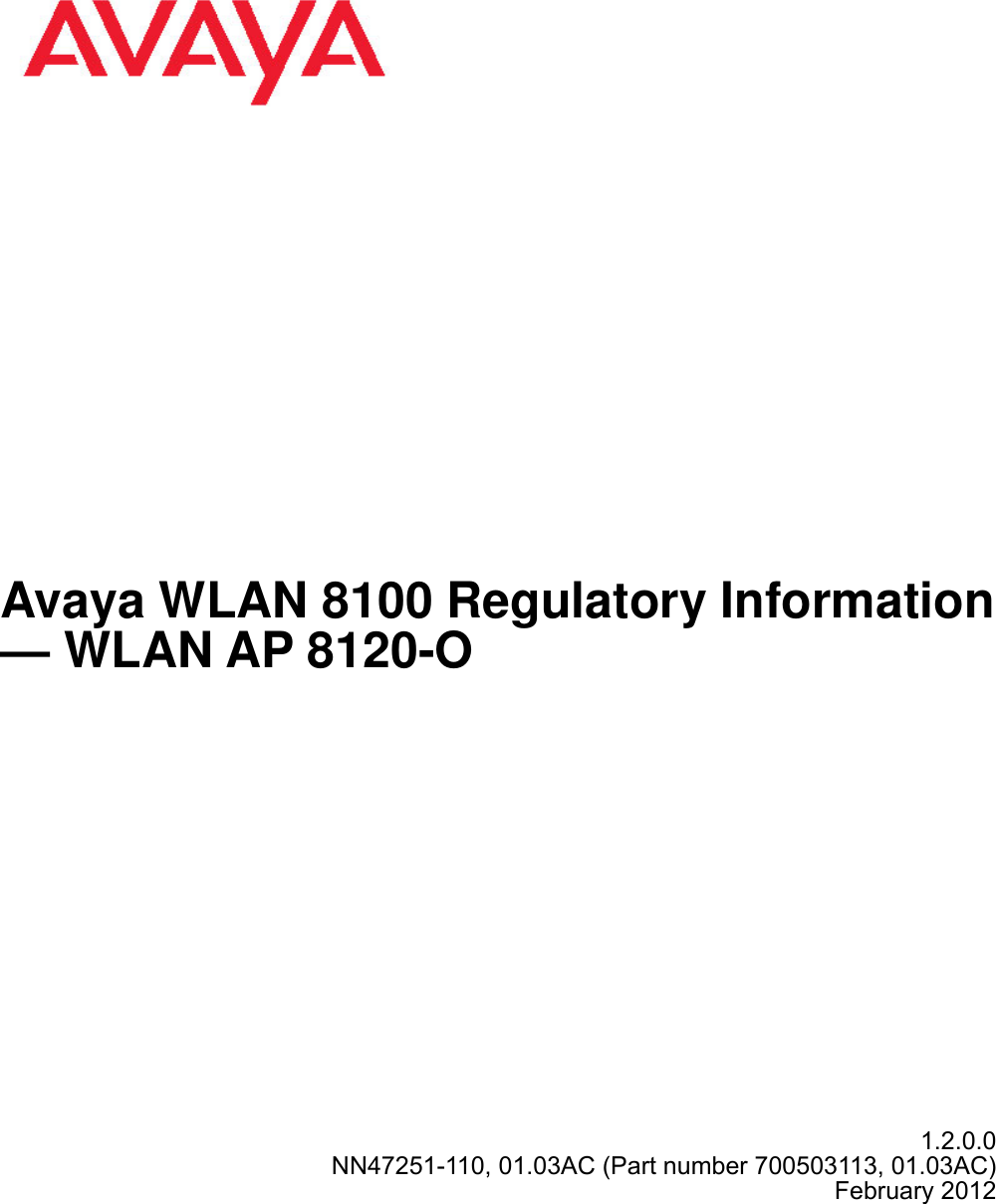
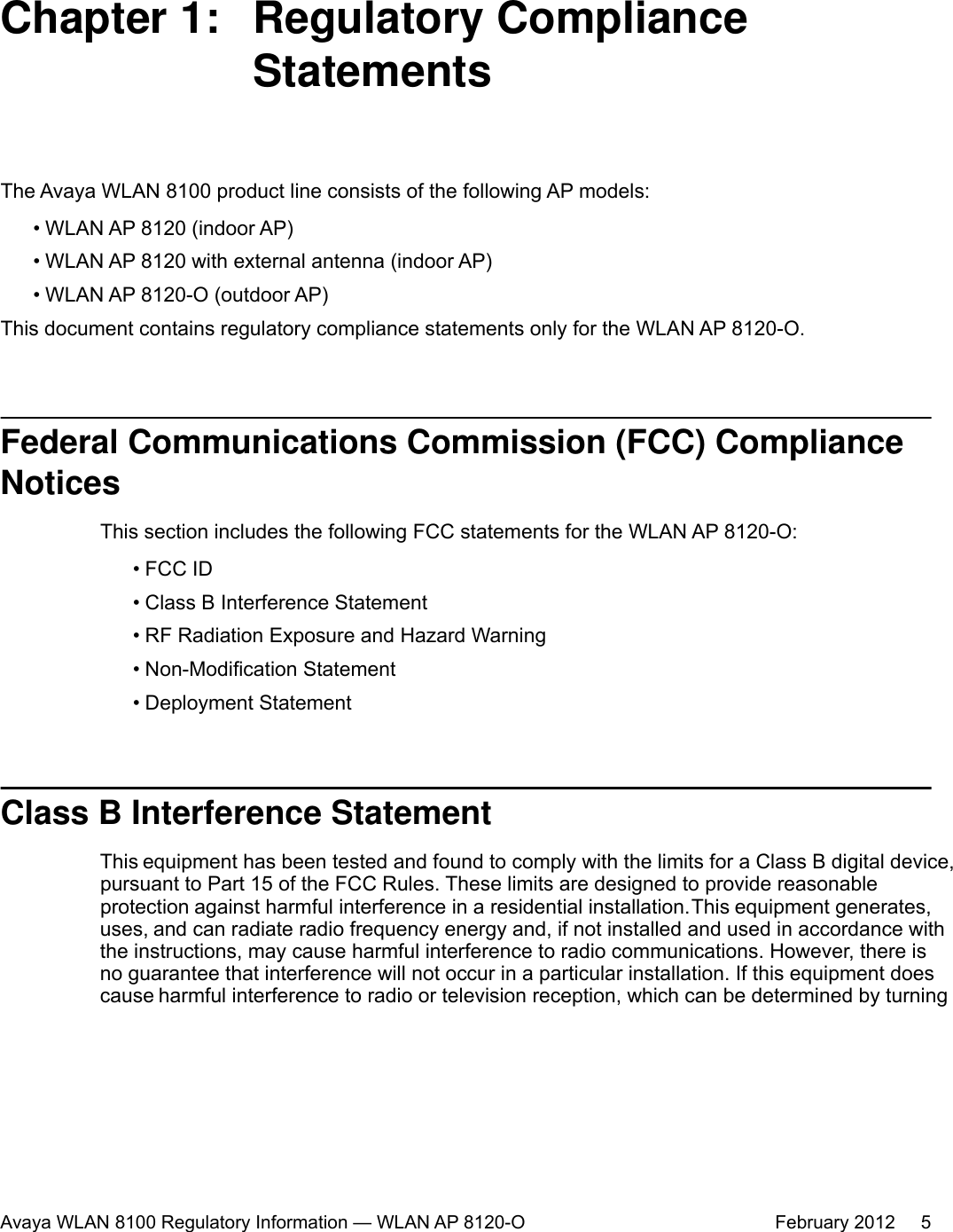
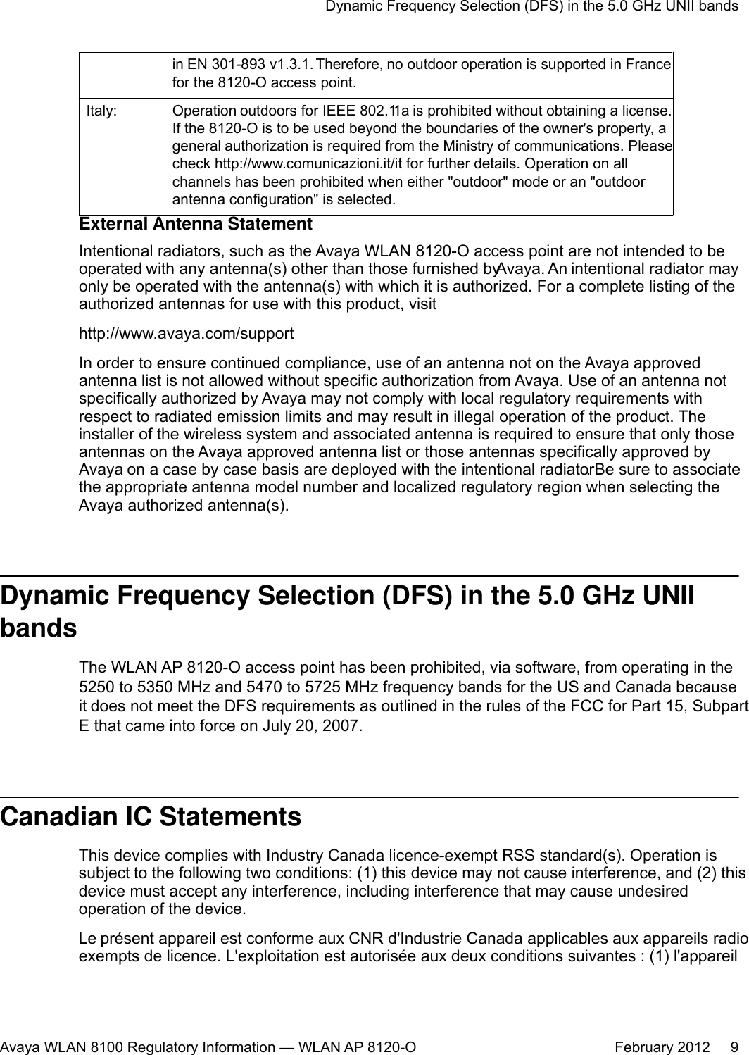
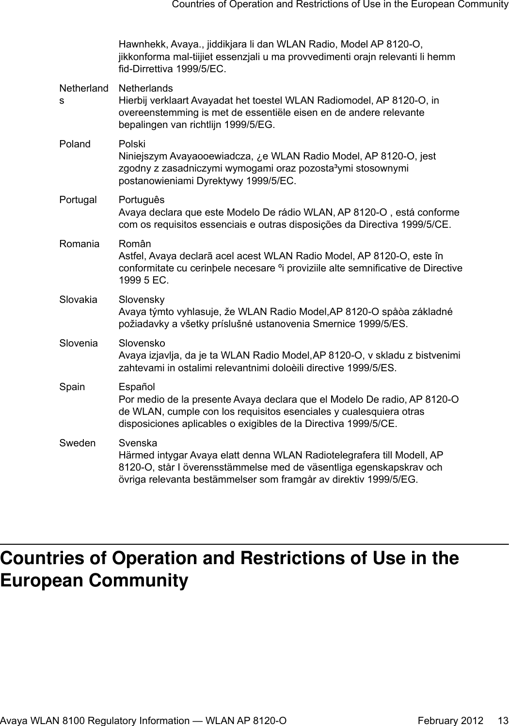


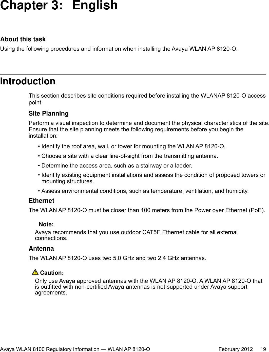
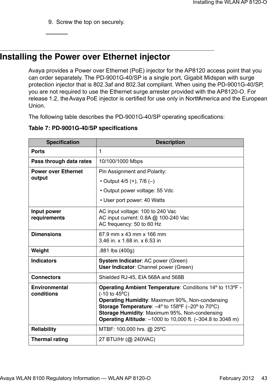
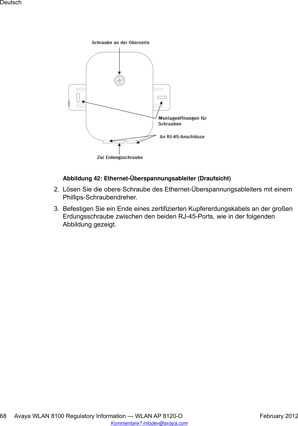
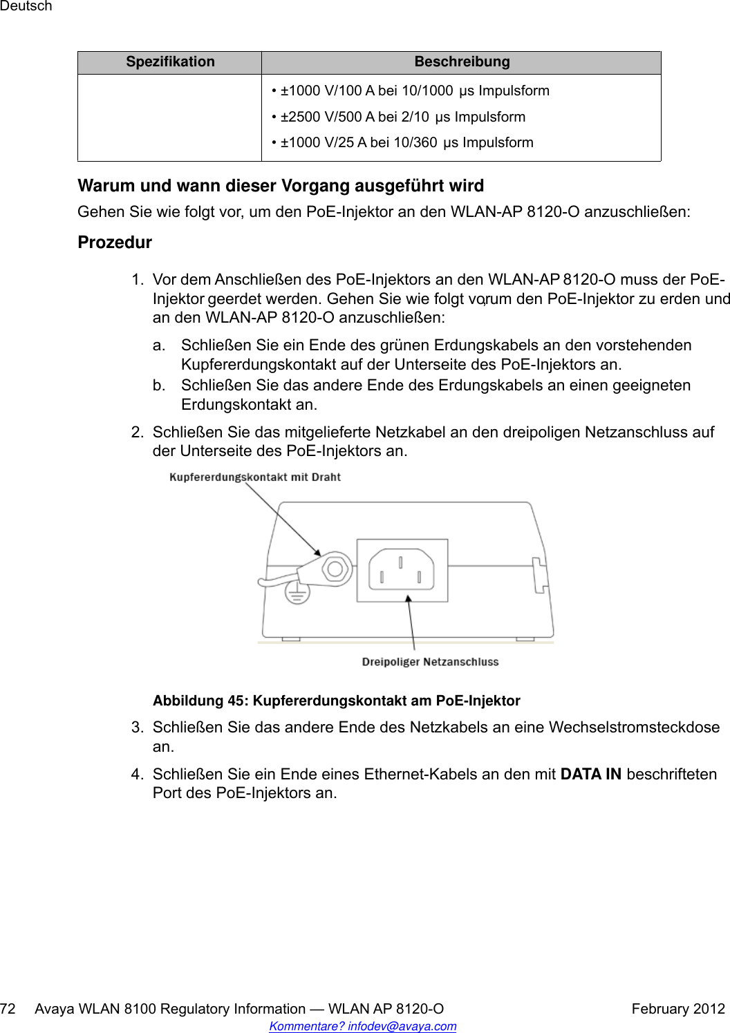
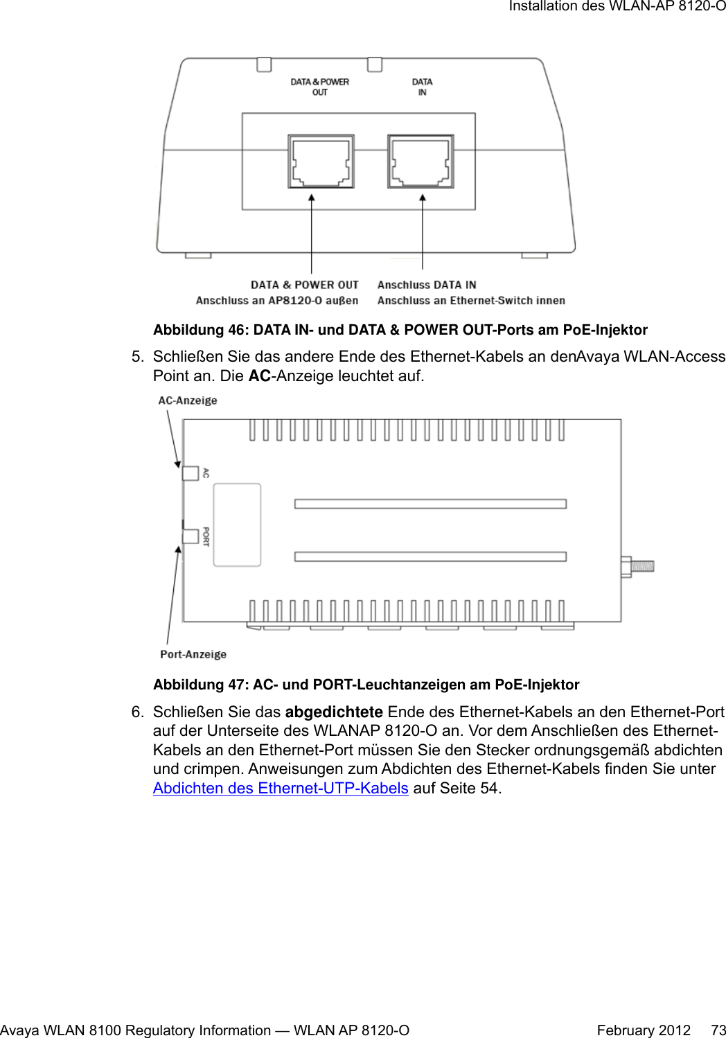
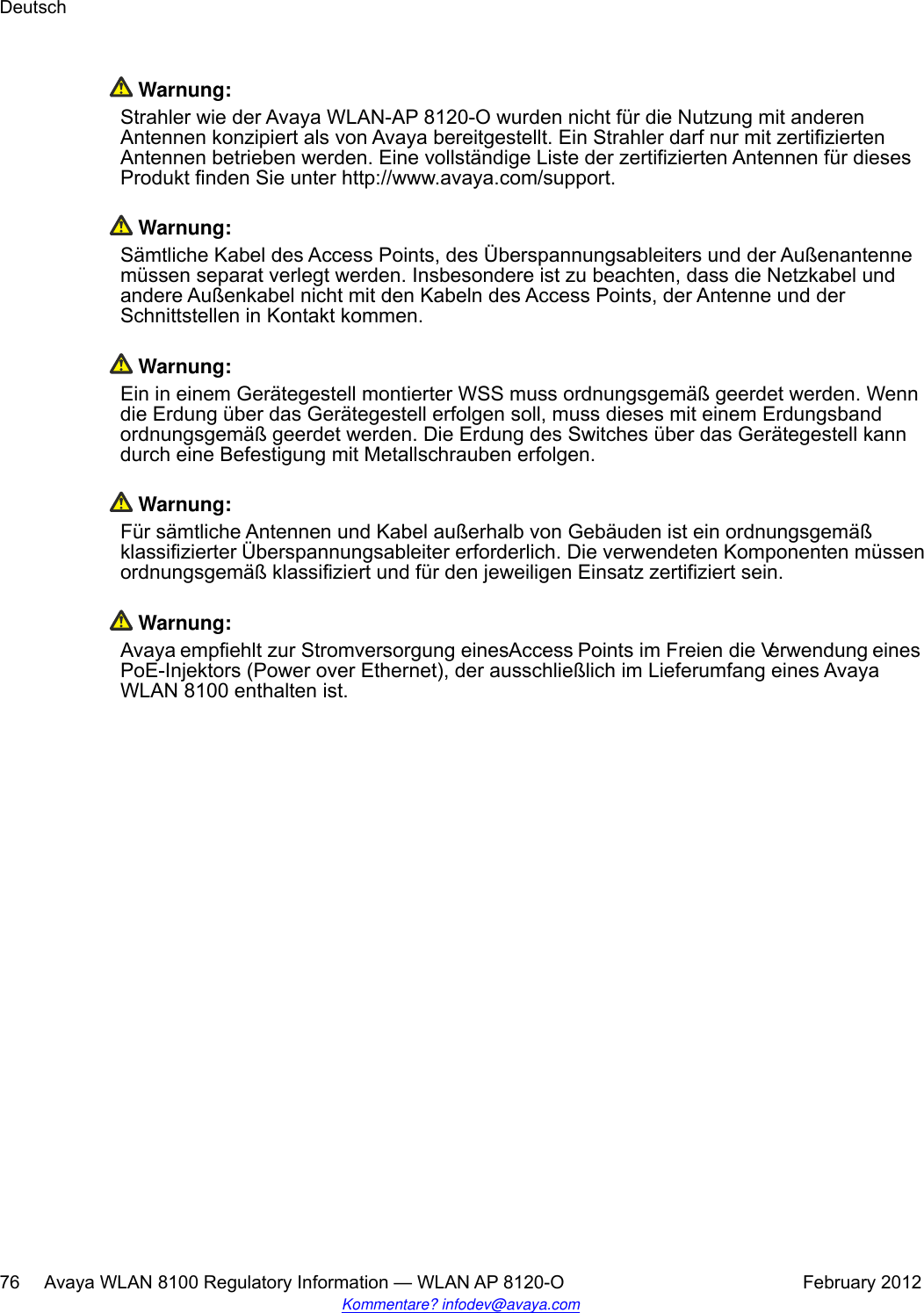
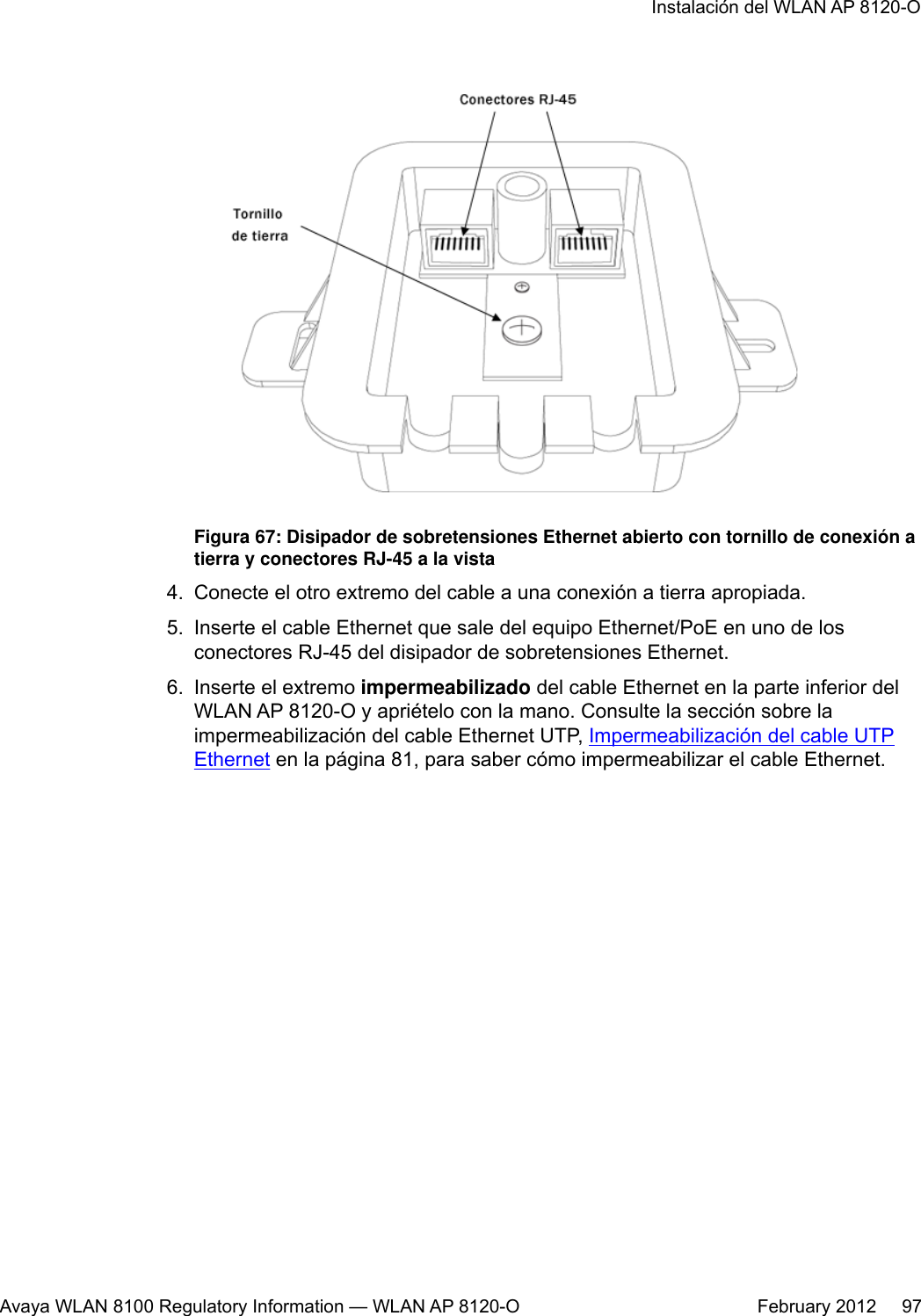
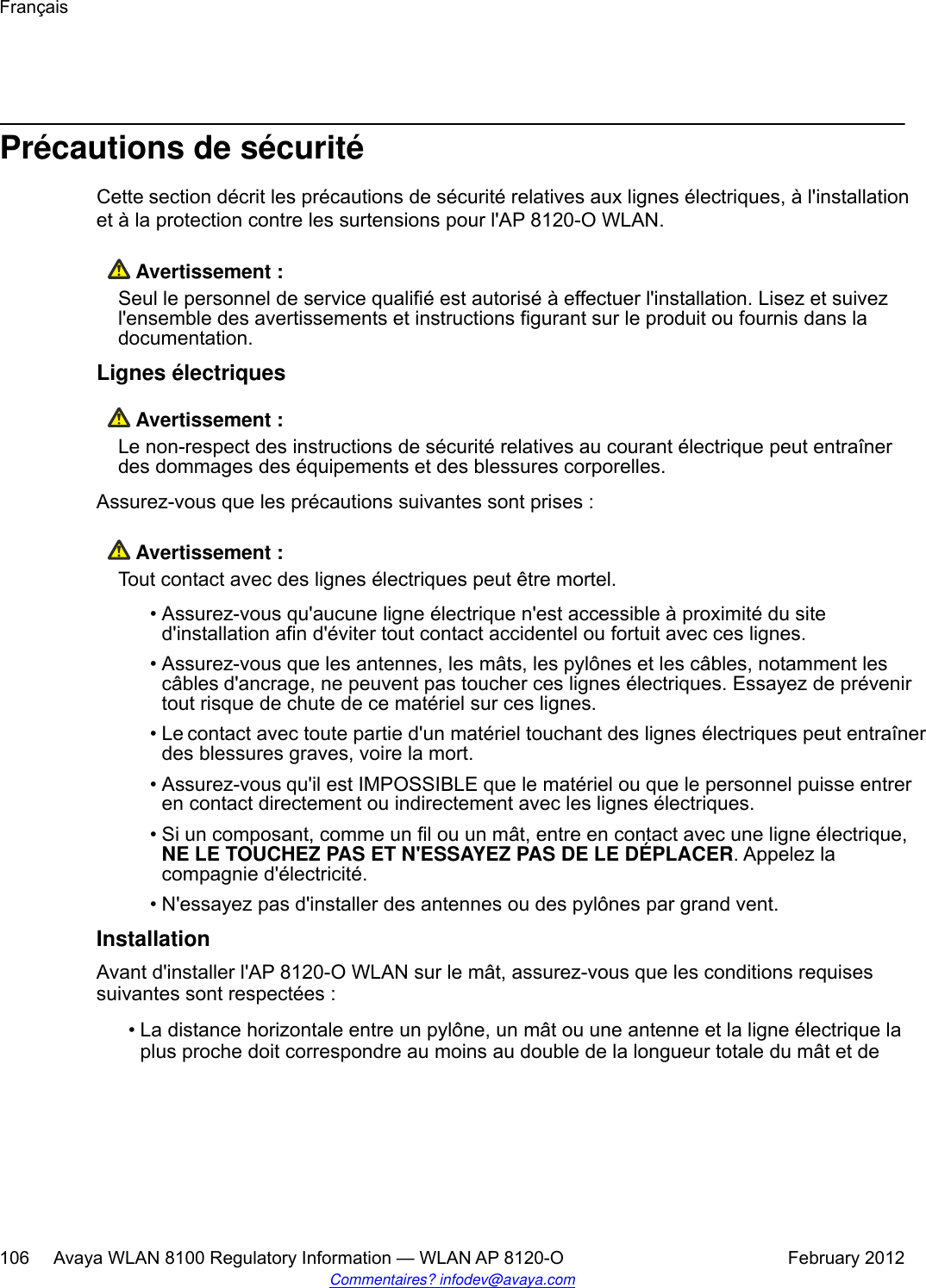
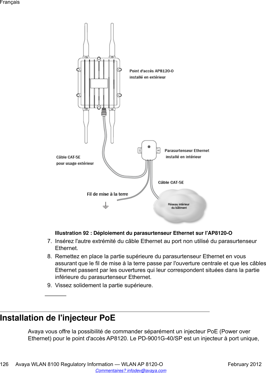
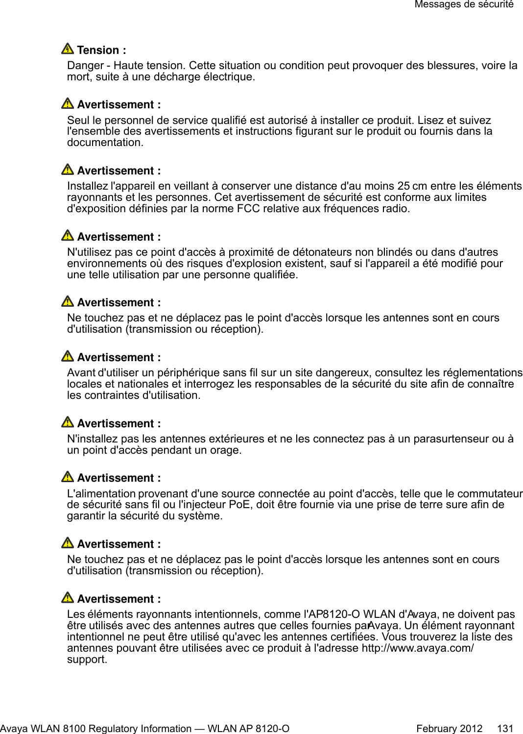
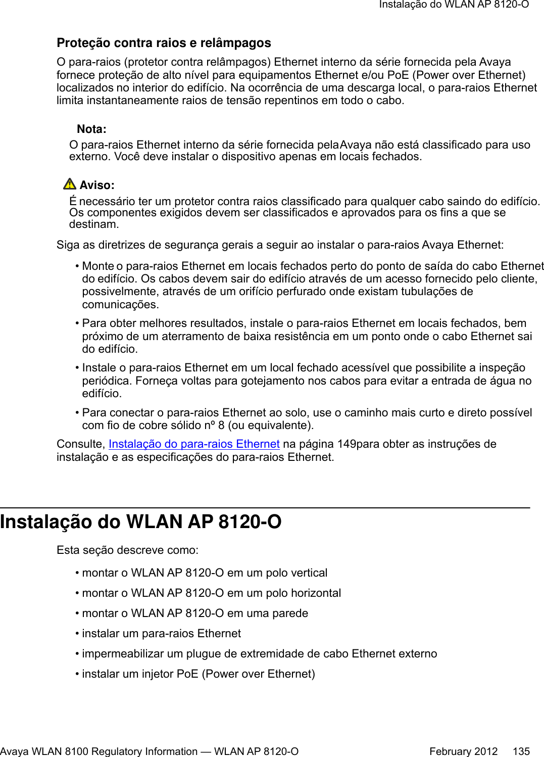
![Specification DescriptionSurge protection Meets surge protection as specified in GR-1089-Core CriteriaB:• ± 1000V/100A @ 10/1000 [μS] Waveform•± 2500V/500A @ 2/10 [μS] Waveform• ± 1000V/25A @ 10/360 [μS] WaveformAbout this taskTo install the Power over Ethernet to the WLAN AP 8120-O , complete the following:Procedure1. Before connecting the Power on Ethernet adapter to the WLAN AP 8120-O youmust first ground the PoE. To ground and connect the PoE to the WLAN AP 8120-O, complete the following:a. Connect one end of the green grounding wire to the protruding copper groundpost on the bottom of the PoE.b. Connect the other end of the ground wire to an acceptable Earth ground.2. Attach the supplied power plug to the three-prong plug outlet on the bottom of thePoE adapter.Figure 21: Copper ground post on PoE3. Connect the other end to a working AC outlet.4. Insert one end of an Ethernet cable into the DATA IN port on the PoE adapter.English44 Avaya WLAN 8100 Regulatory Information — WLAN AP 8120-O February 2012Comments? infodev@avaya.com](https://usermanual.wiki/Senao-Networks/AP8120-O/User-Guide-1663909-Page-44.png)
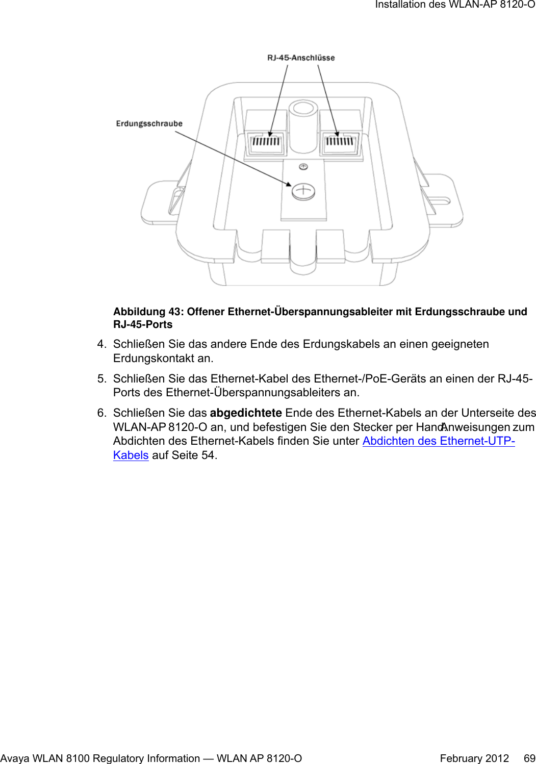
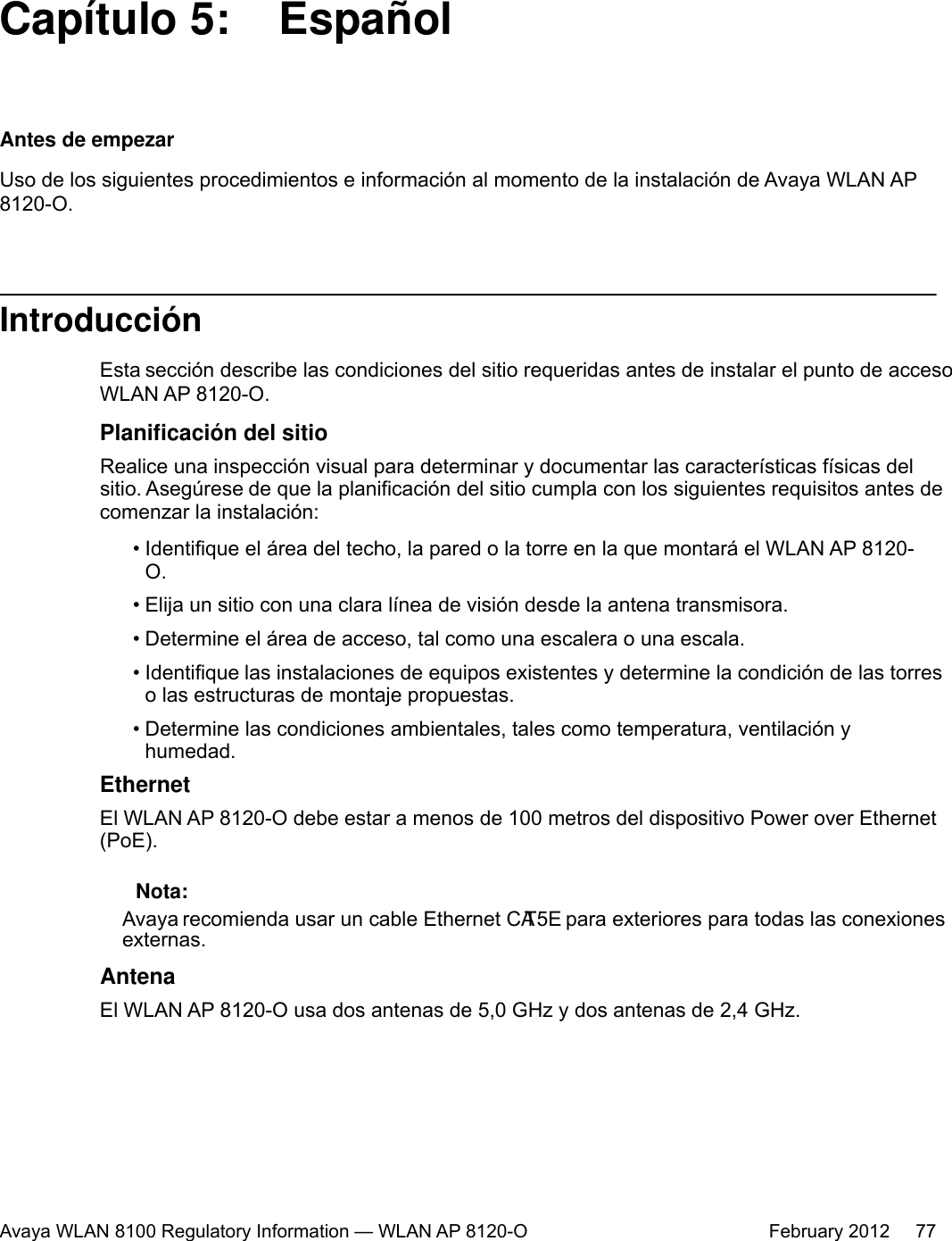

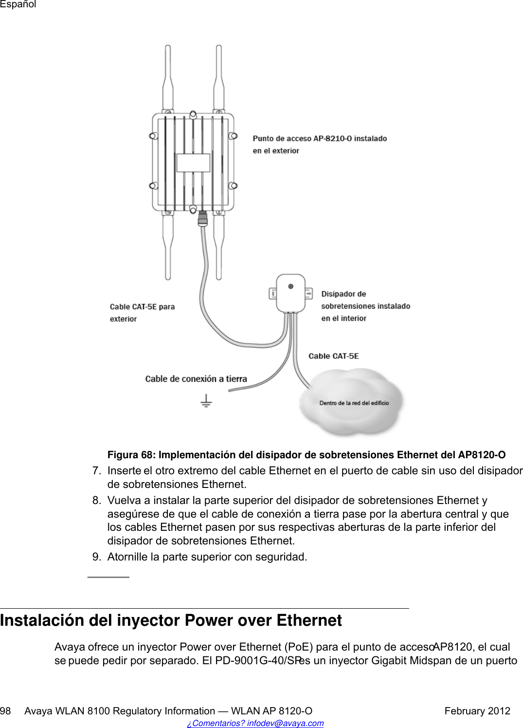
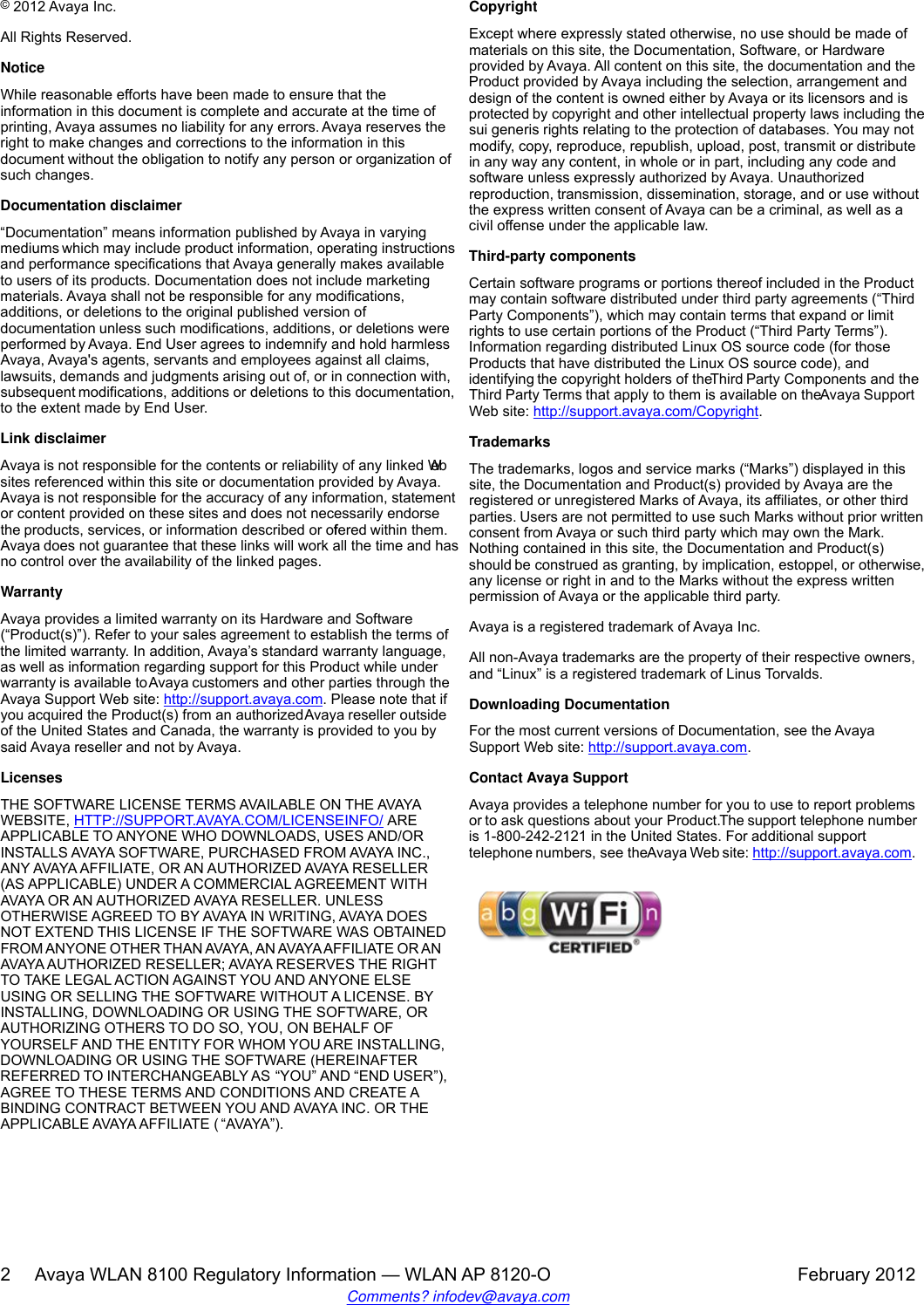
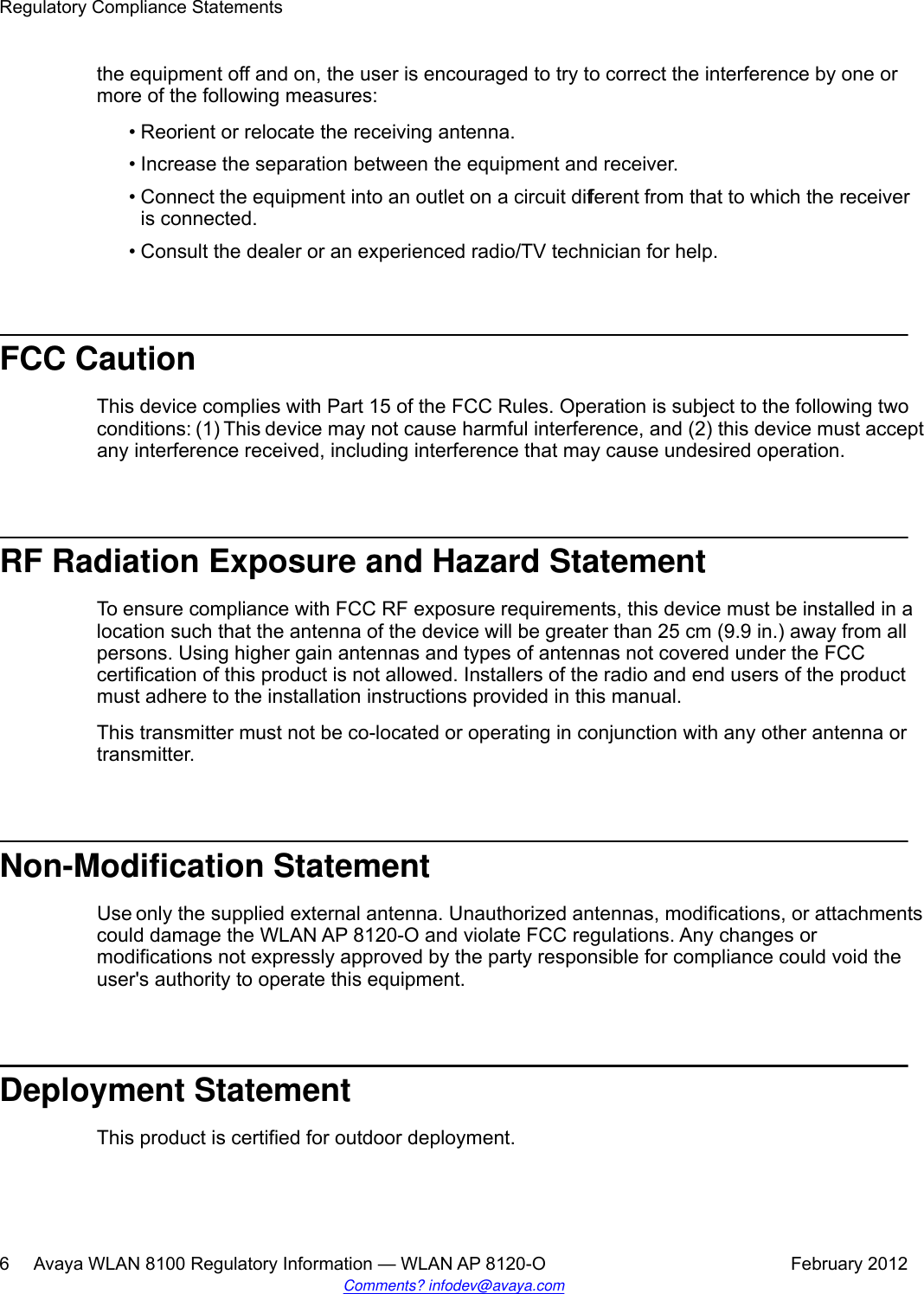
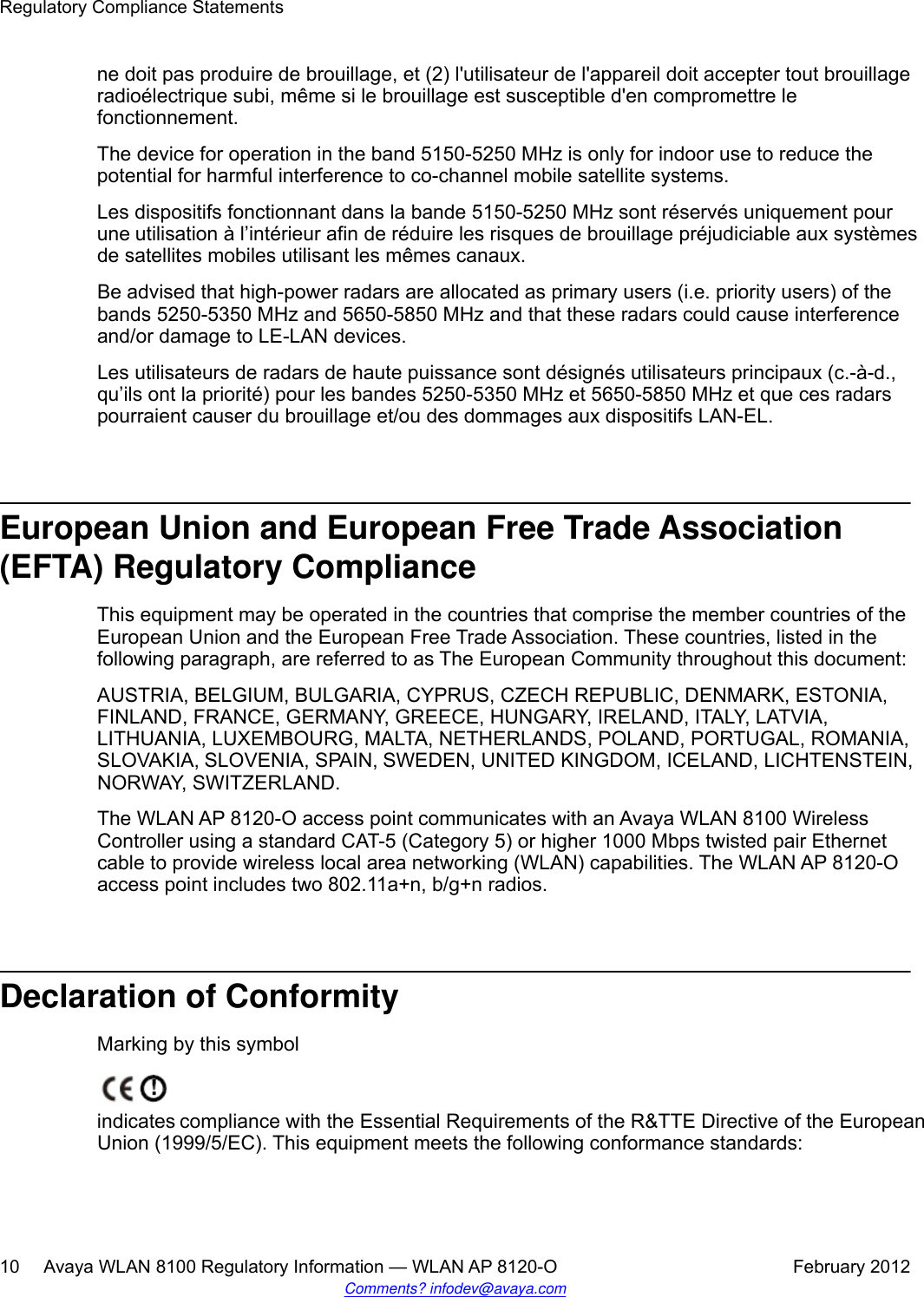
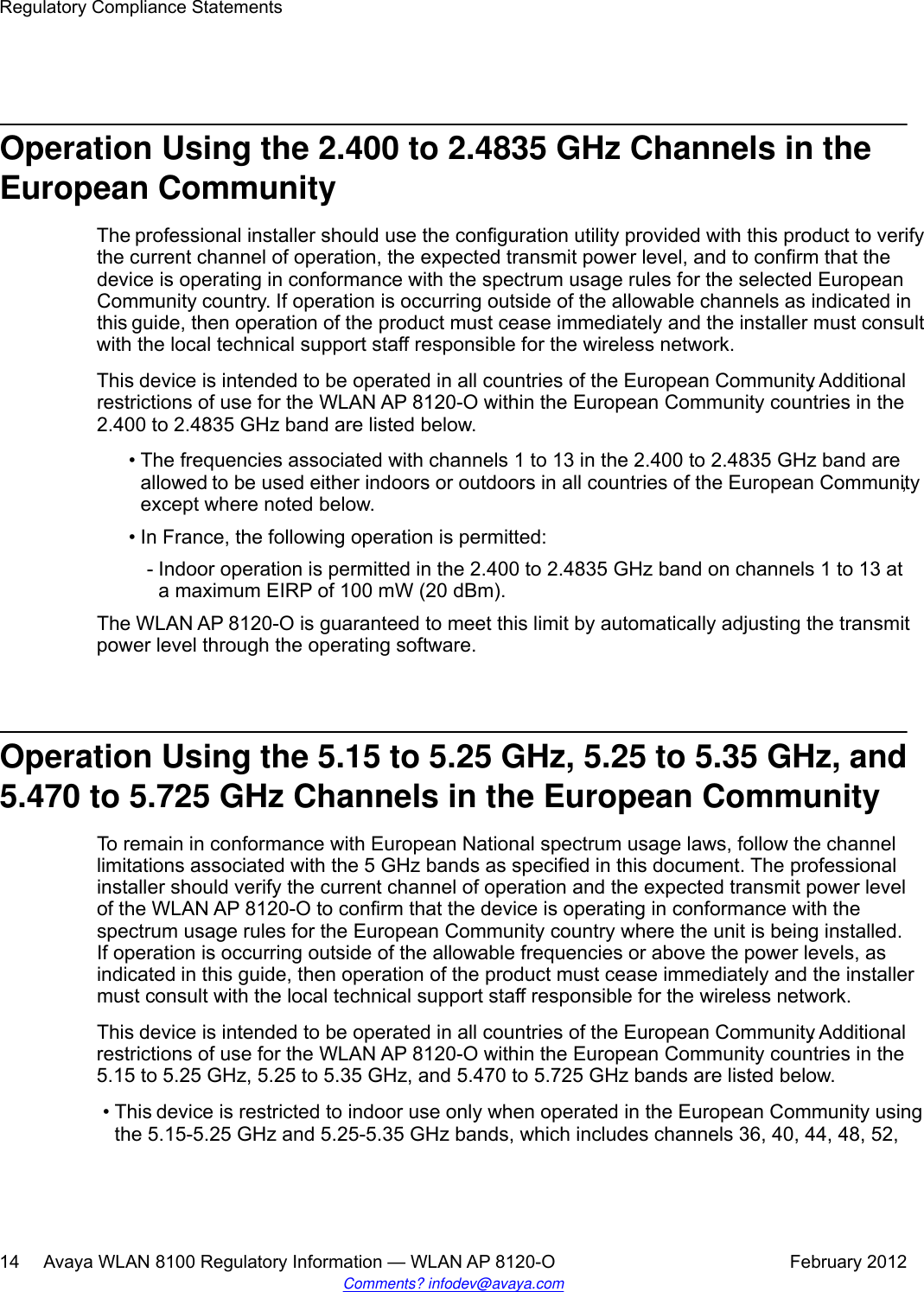
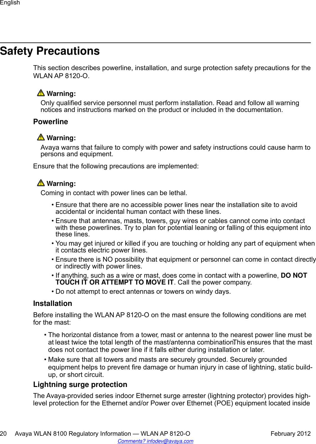
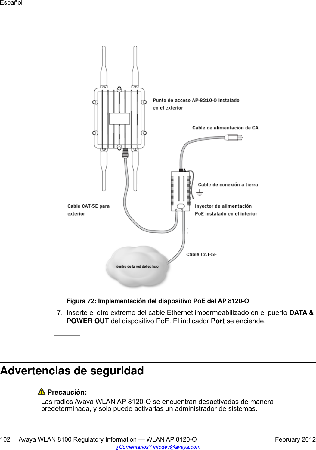
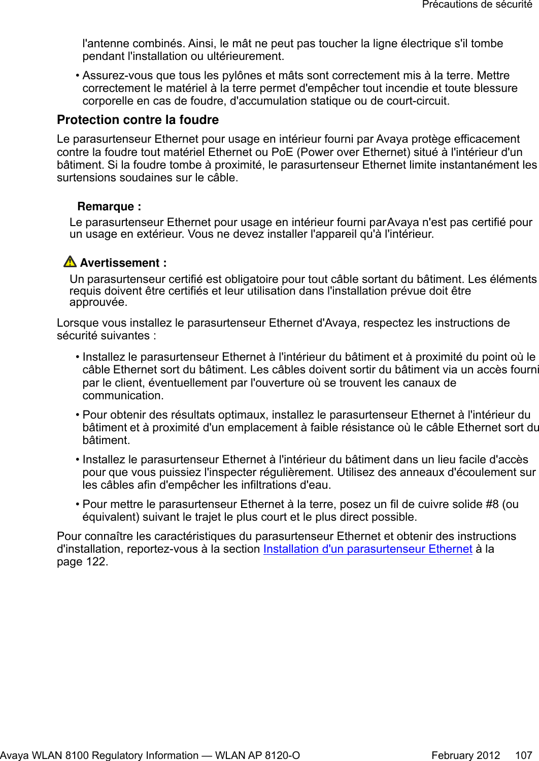
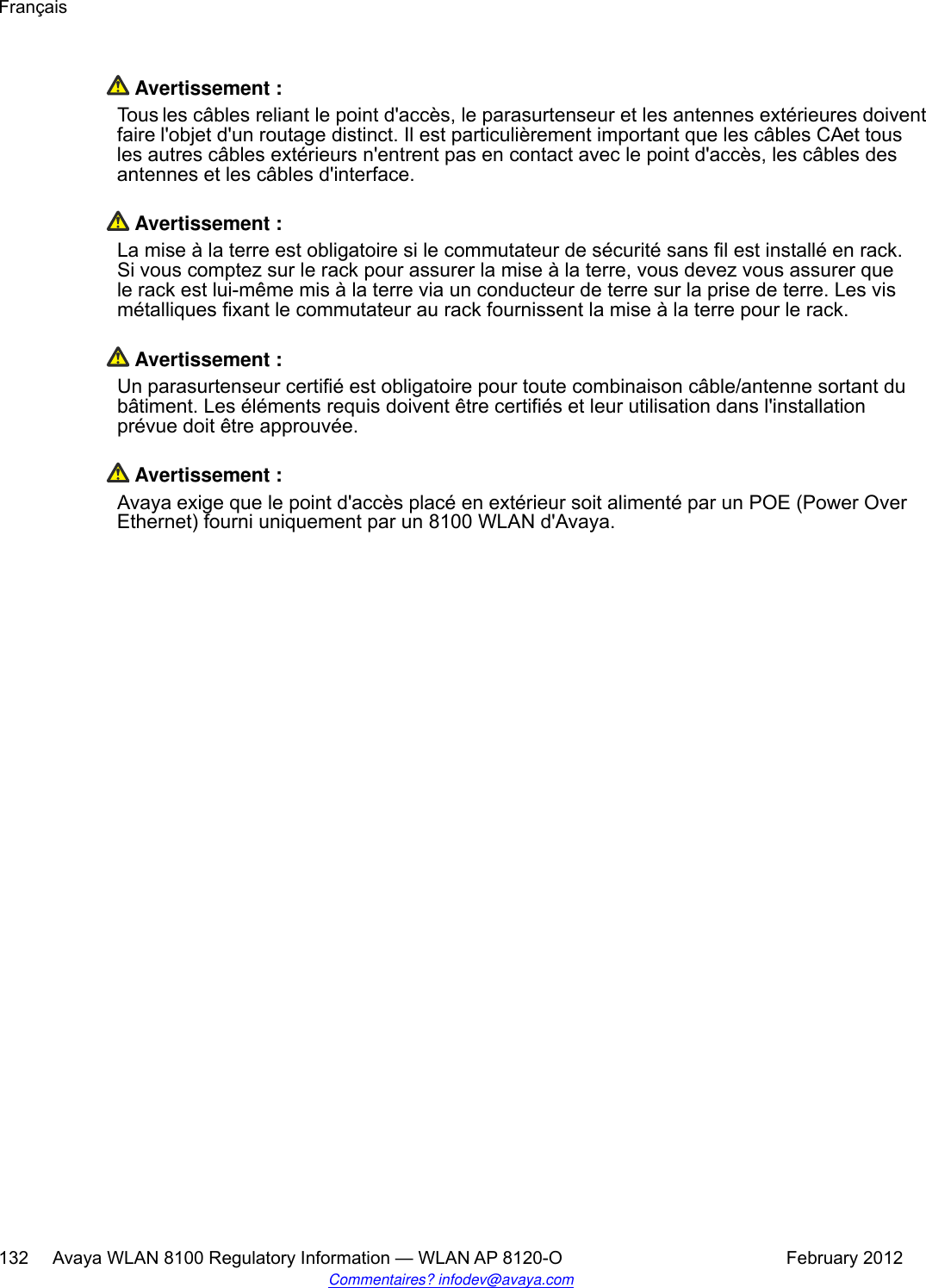
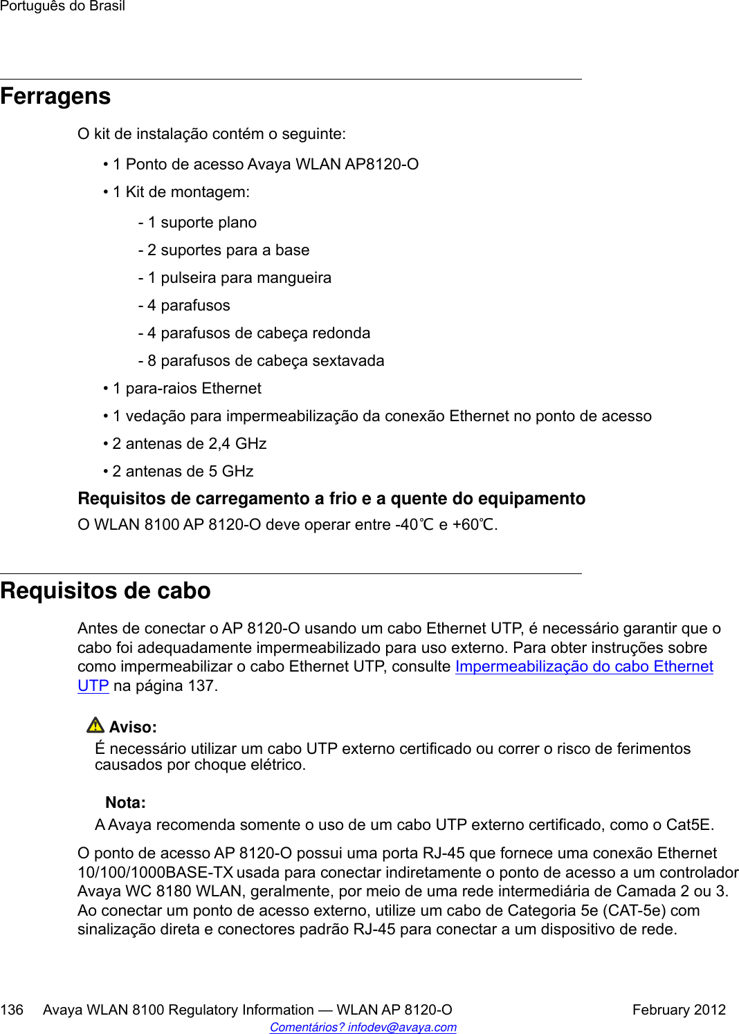
![Especificación Descripción• ± 1000V/100A en forma de onda 10/1000 [μS]• ± 2500V/500A en forma de onda 2/10 [μS]• ± 1000V/25A en forma de onda 10/360 [μS]Antes de empezarPara instalar el dispositivo Power over Ethernet en el WLAN AP 8120-O, realice lo siguiente:Procedimiento1. Antes de conectar el adaptador Power on Ethernet al WLAN AP 8120-O, primerodebe conectar a tierra el dispositivo PoE. Para conectar a tierra y conectar eldispositivo PoE al WLAN AP 8120-O, realice lo siguiente:a. Conecte un extremo del cable de conexión a tierra verde al borne de conexióna tierra de cobre sobresaliente de la parte inferior del dispositivo PoE.b. Conecte el otro extremo del cable de conexión a tierra a una conexión a tierraaceptable.2. Conecte el enchufe de alimentación suministrado a la salida del enchufe de trespatas de la parte inferior del adaptador PoE.Figura 69: Borne de conexión a tierra de cobre en el dispositivo PoE3. Conecte el otro extremo a un tomacorriente de CA activo.4. Inserte un extremo de un cable Ethernet en el puerto DATA IN del adaptadorPoE.Español100 Avaya WLAN 8100 Regulatory Information — WLAN AP 8120-O February 2012¿Comentarios? infodev@avaya.com](https://usermanual.wiki/Senao-Networks/AP8120-O/User-Guide-1663909-Page-100.png)
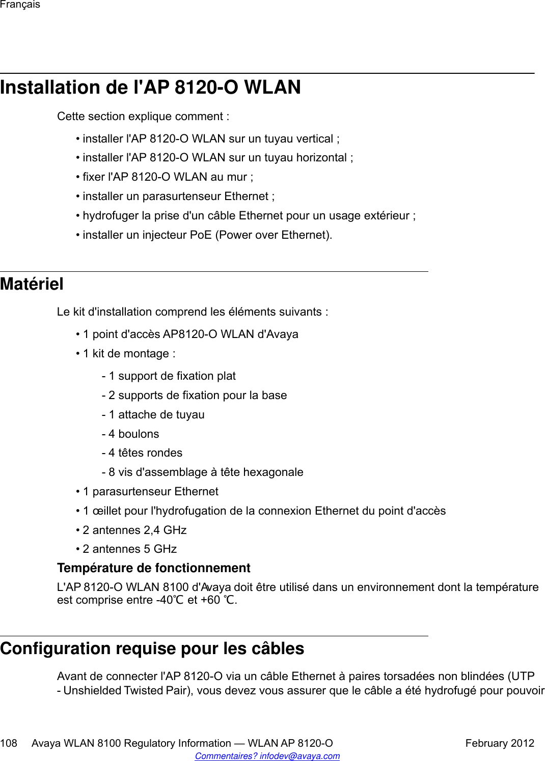
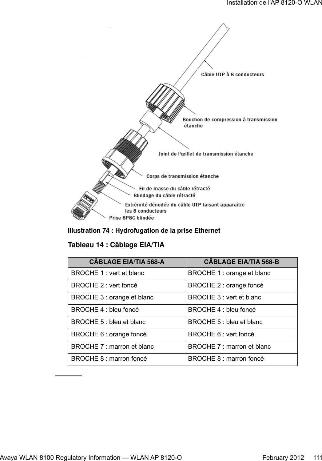
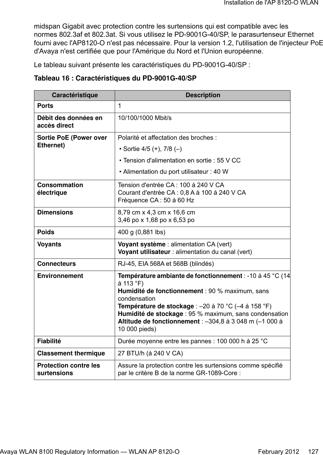
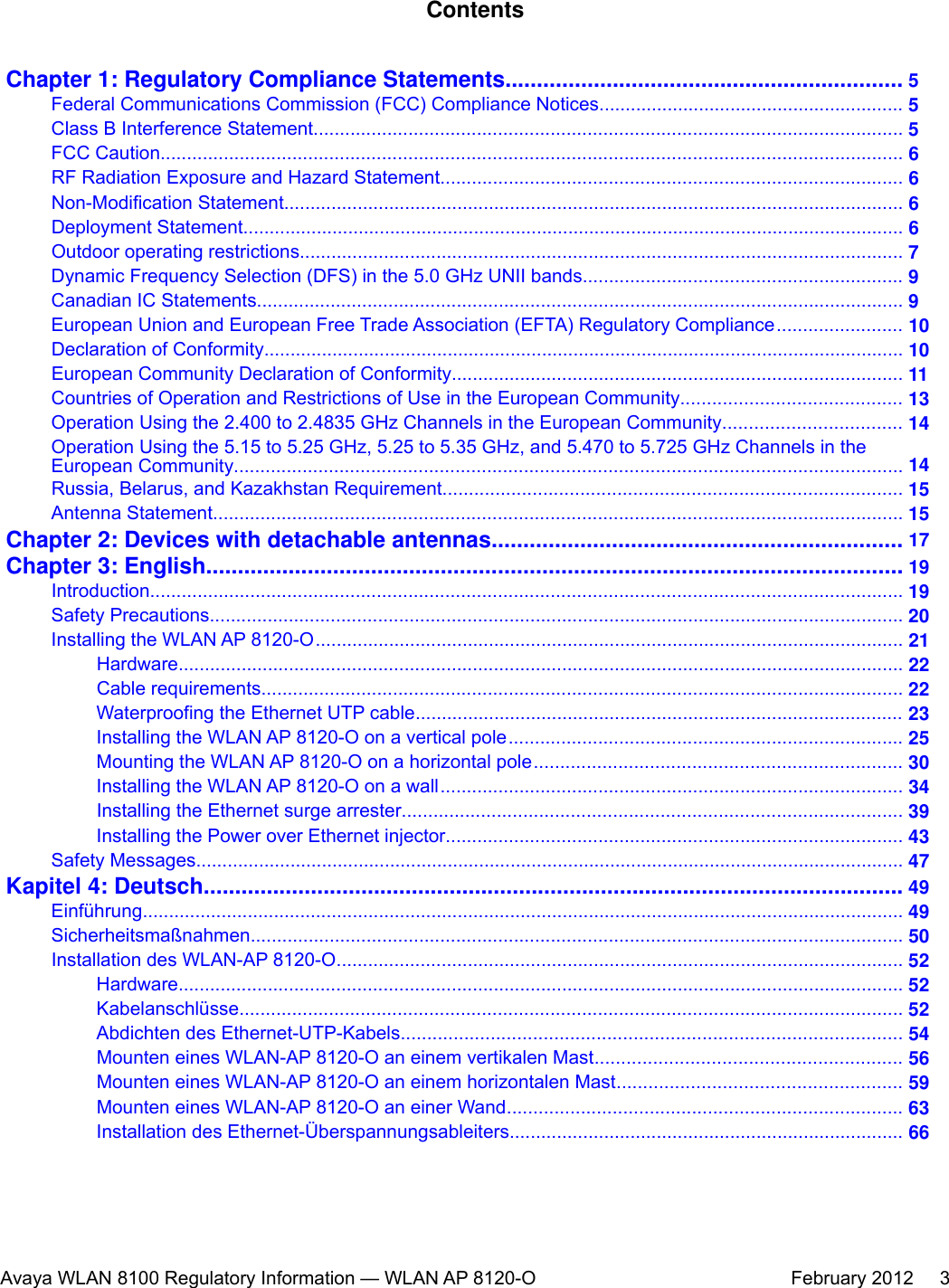
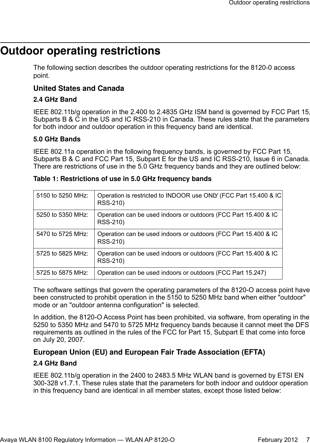
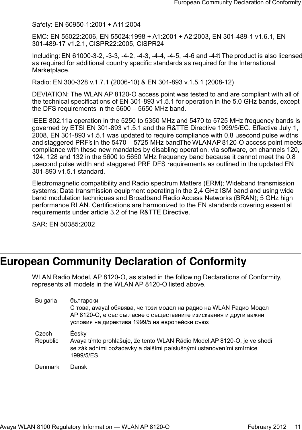
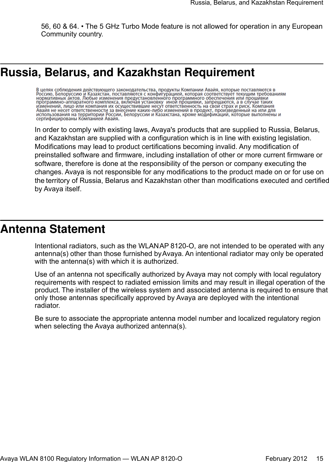
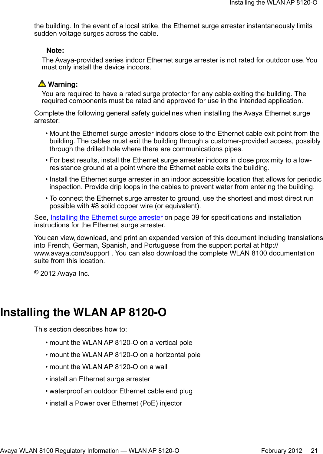
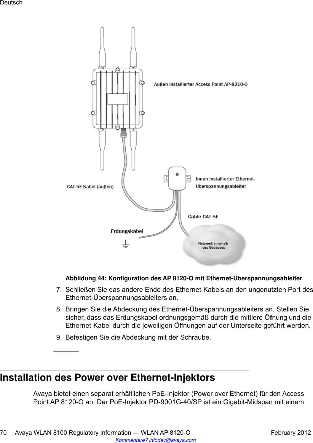
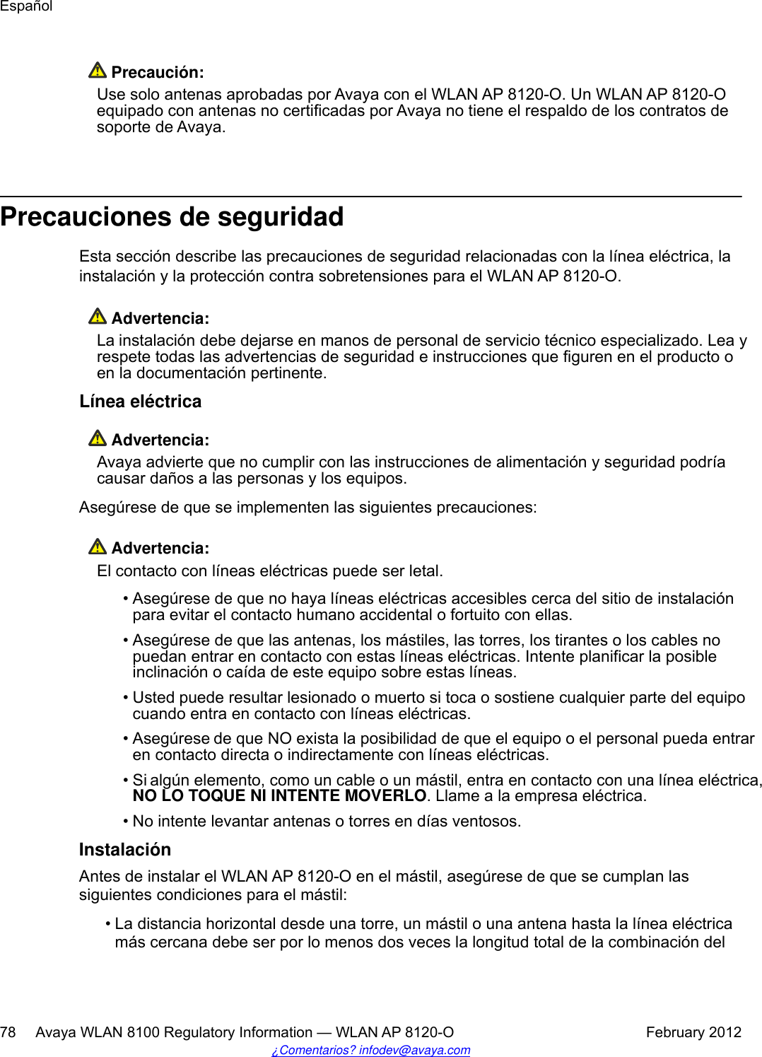
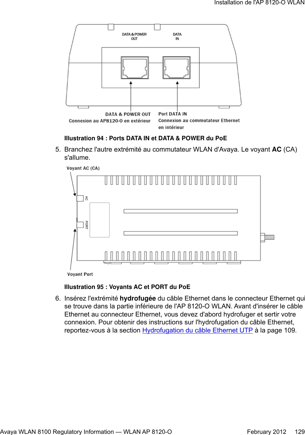
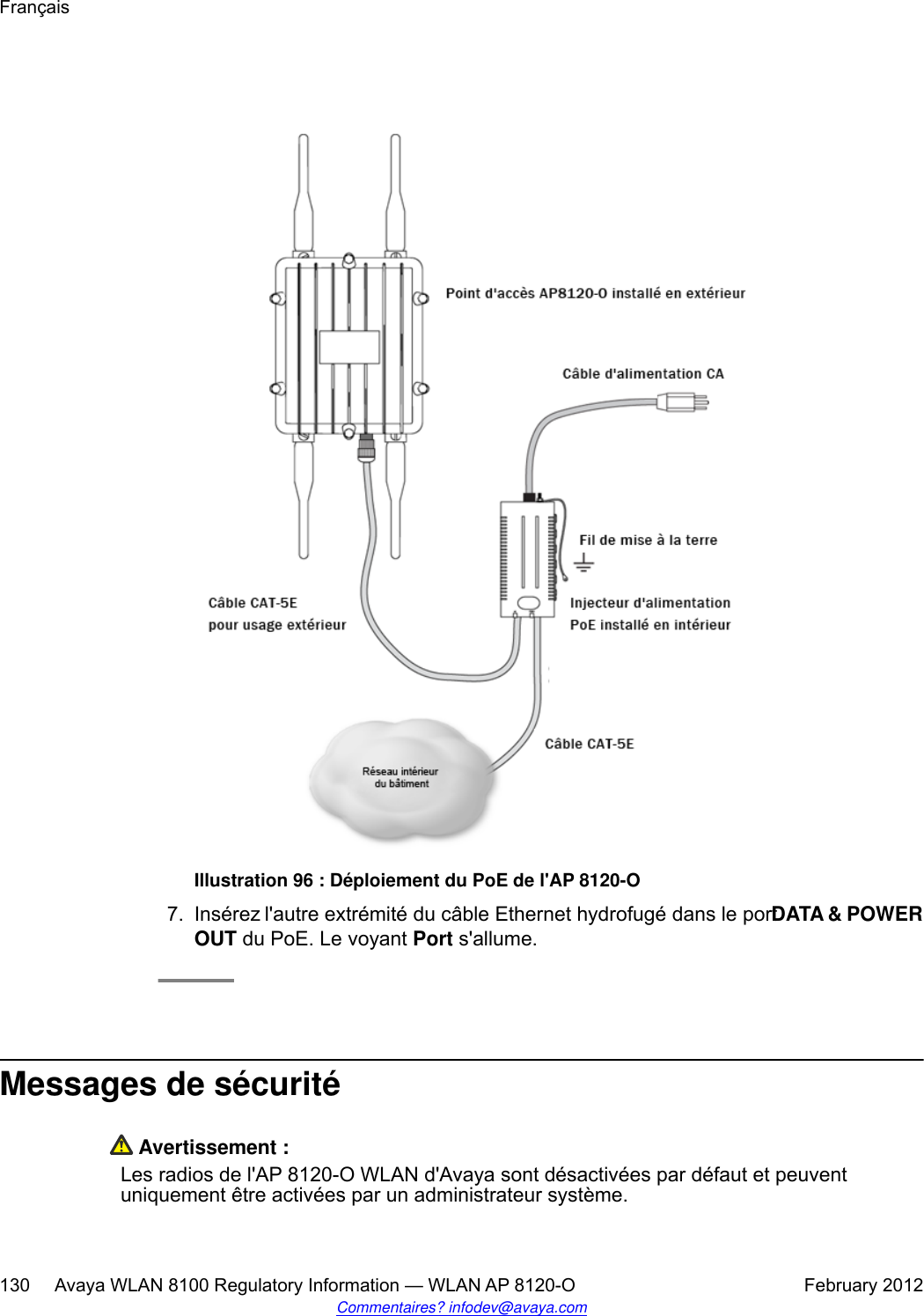
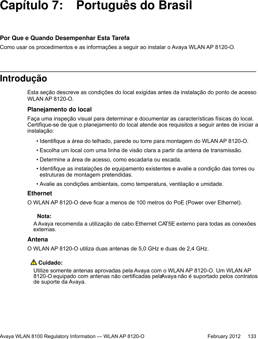
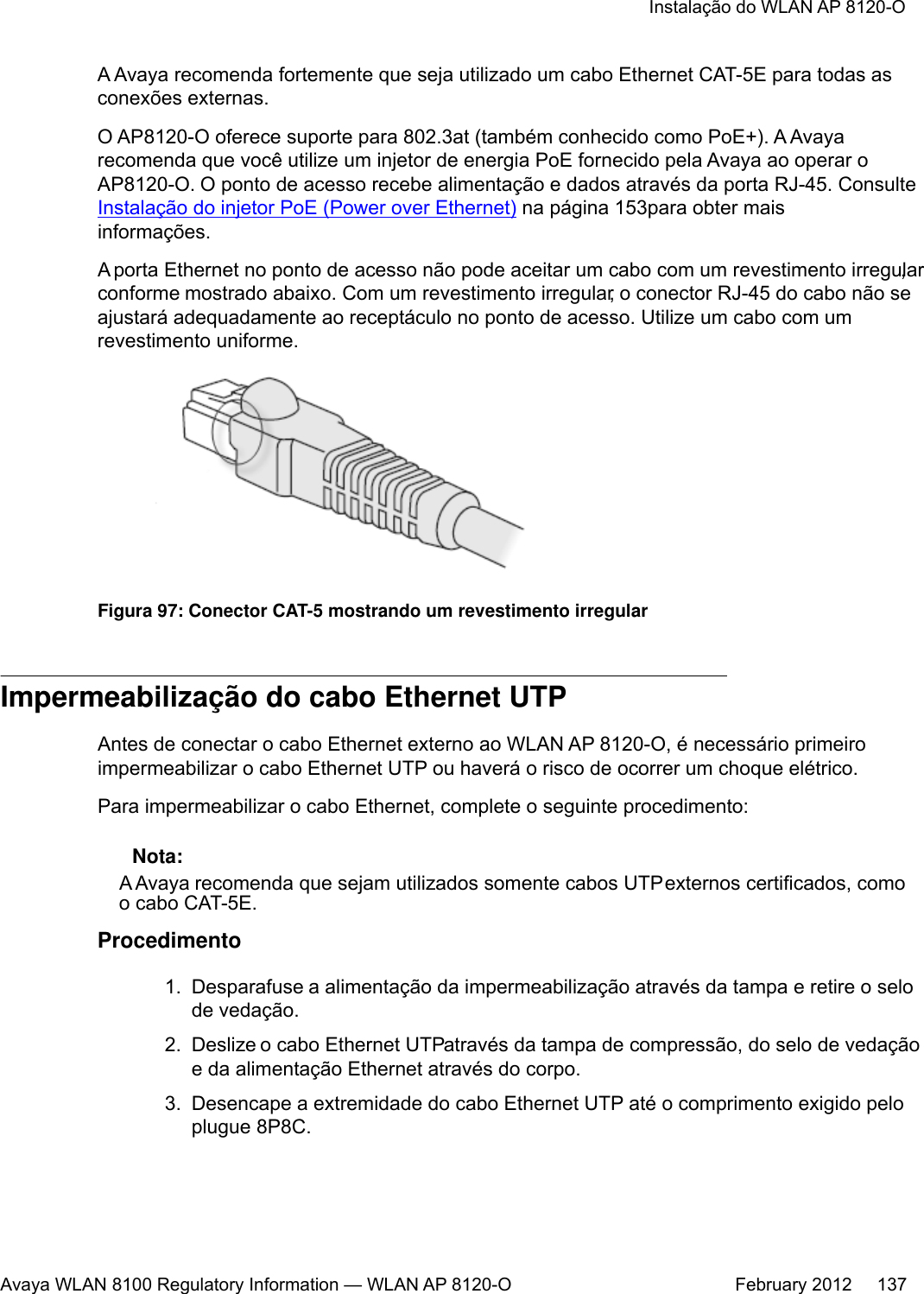
![Caractéristique Description• ± 1 000 V/100 A à 10/1000 [μS] (forme d'onde)• ± 2 500 V/500 A à 2/10 [μS] (forme d'onde)•± 1 000 V/25 A à 10/360 [μS] (forme d'onde)Pourquoi et quand exécuter cette tâchePour installer le PoE sur l'AP 8120-O WLAN, procédez comme suit :Procédure1. Avant de connecter l'adaptateur PoE sur l'AP 8120-O WLAN, vous devez d'abordmettre le PoE à la terre. Pour ce faire et le connecter à l'AP 8120-O WLAN, procédezcomme suit :a. Branchez une extrémité du fil de mise à la terre vert à l'élément de mise à laterre en cuivre qui se trouve sur la partie inférieure du PoE.b. Branchez l'autre extrémité du fil de mise à la terre à une prise de terreappropriée.2. Branchez la prise d'alimentation fournie à la prise à trois broches située sur la partieinférieure de l'adaptateur PoE.Illustration 93 : Élément de mise à la terre en cuivre du PoE3. Branchez l'autre extrémité à une prise de courant CA qui fonctionne.4. Insérez l'une des extrémités d'un câble Ethernet dans le port DATA IN del'adaptateur PoE.Français128 Avaya WLAN 8100 Regulatory Information — WLAN AP 8120-O February 2012Commentaires? infodev@avaya.com](https://usermanual.wiki/Senao-Networks/AP8120-O/User-Guide-1663909-Page-128.png)
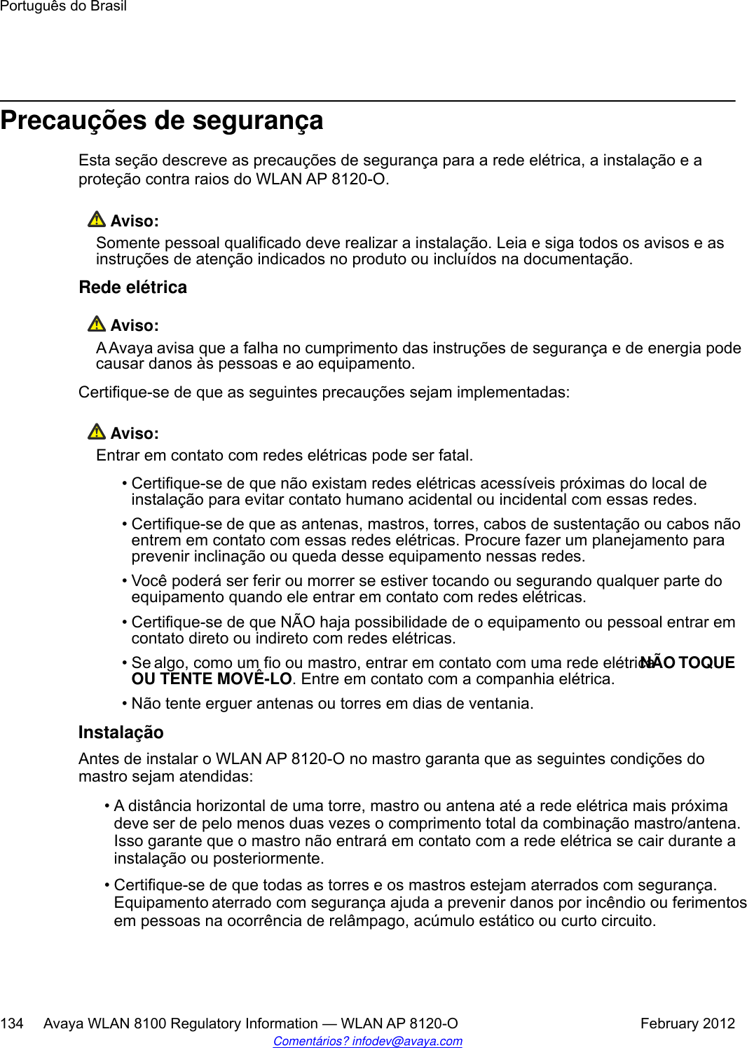
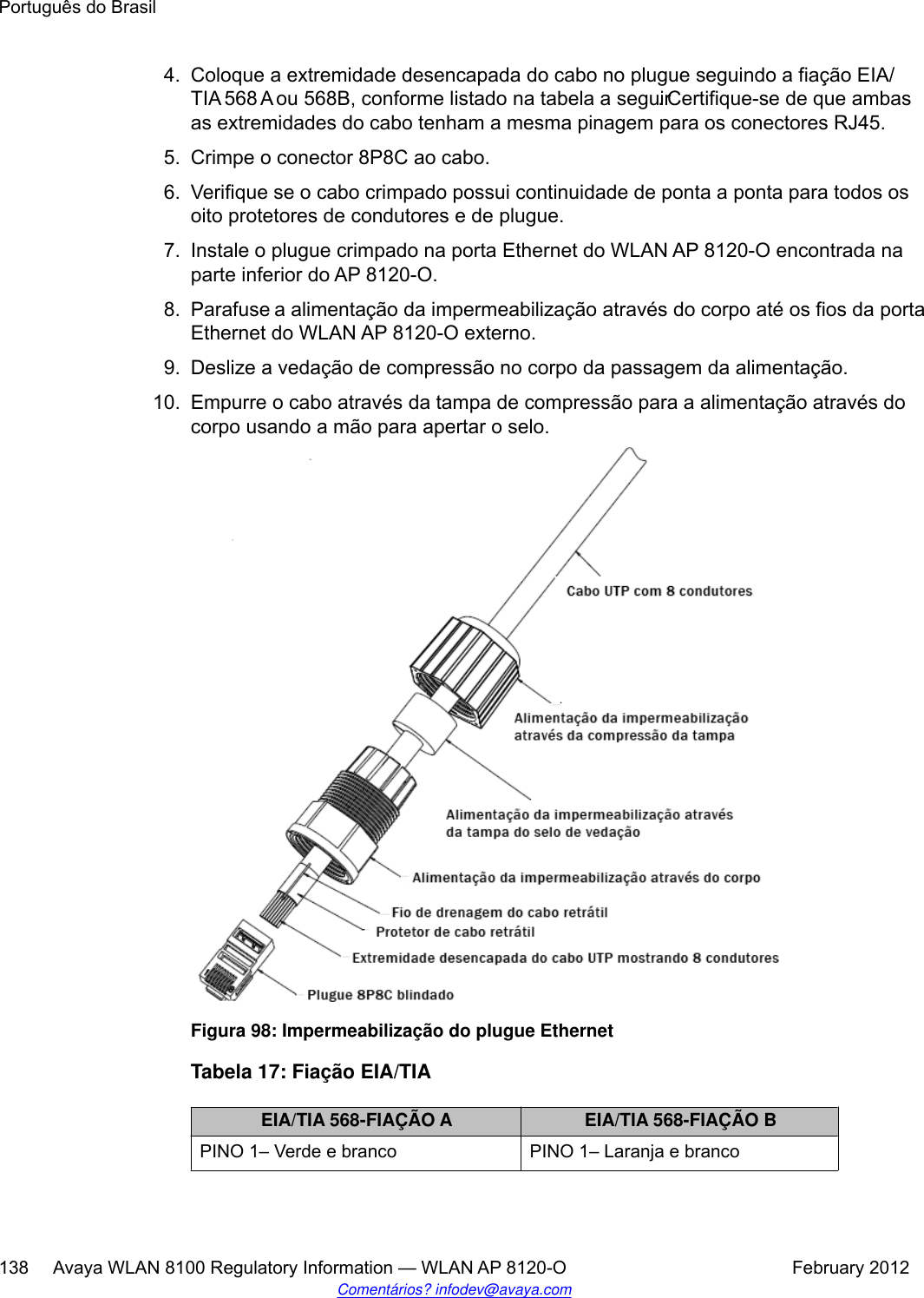

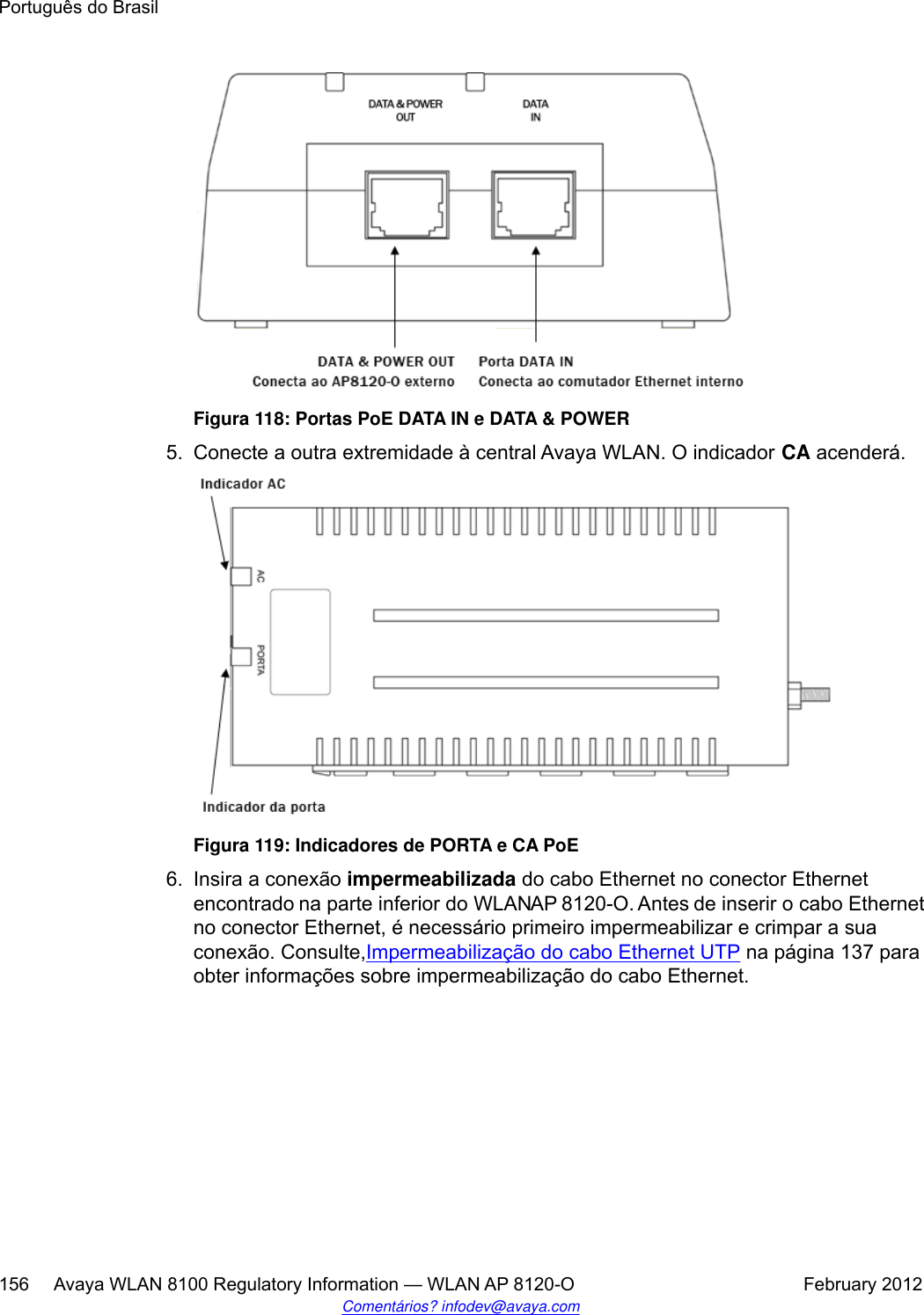
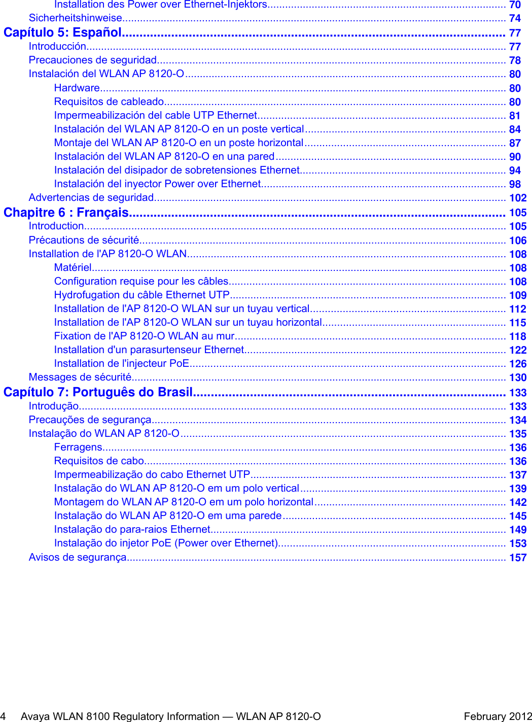
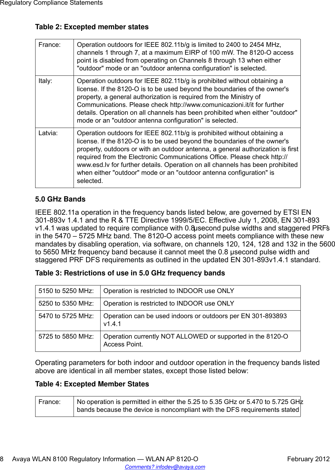
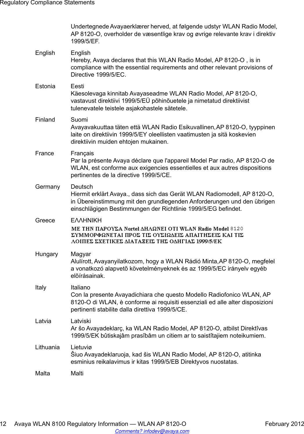
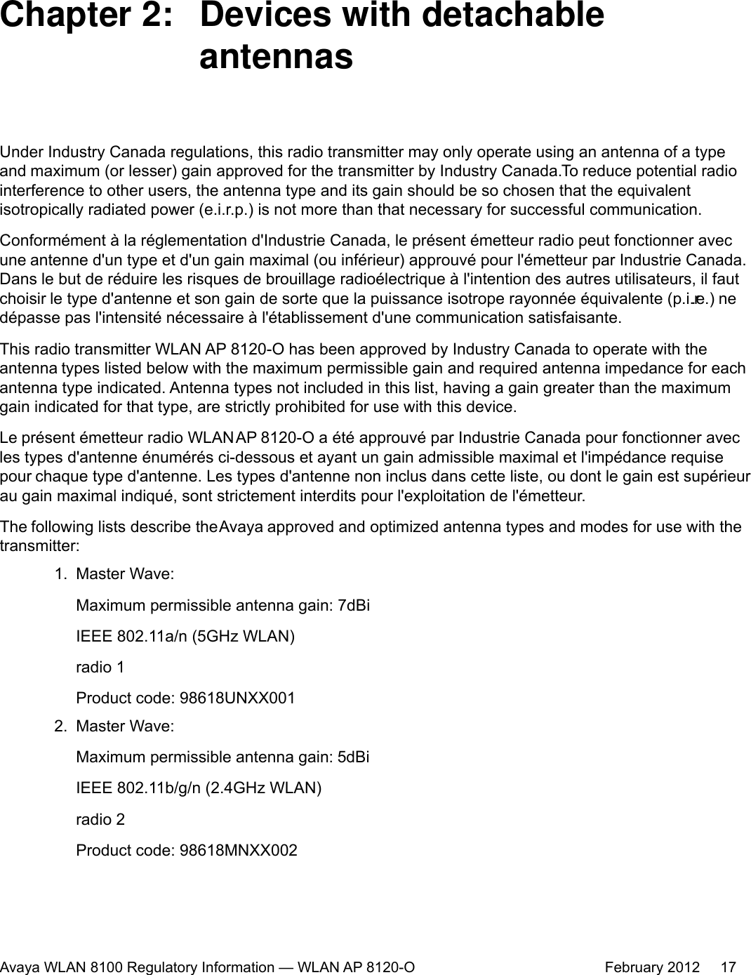
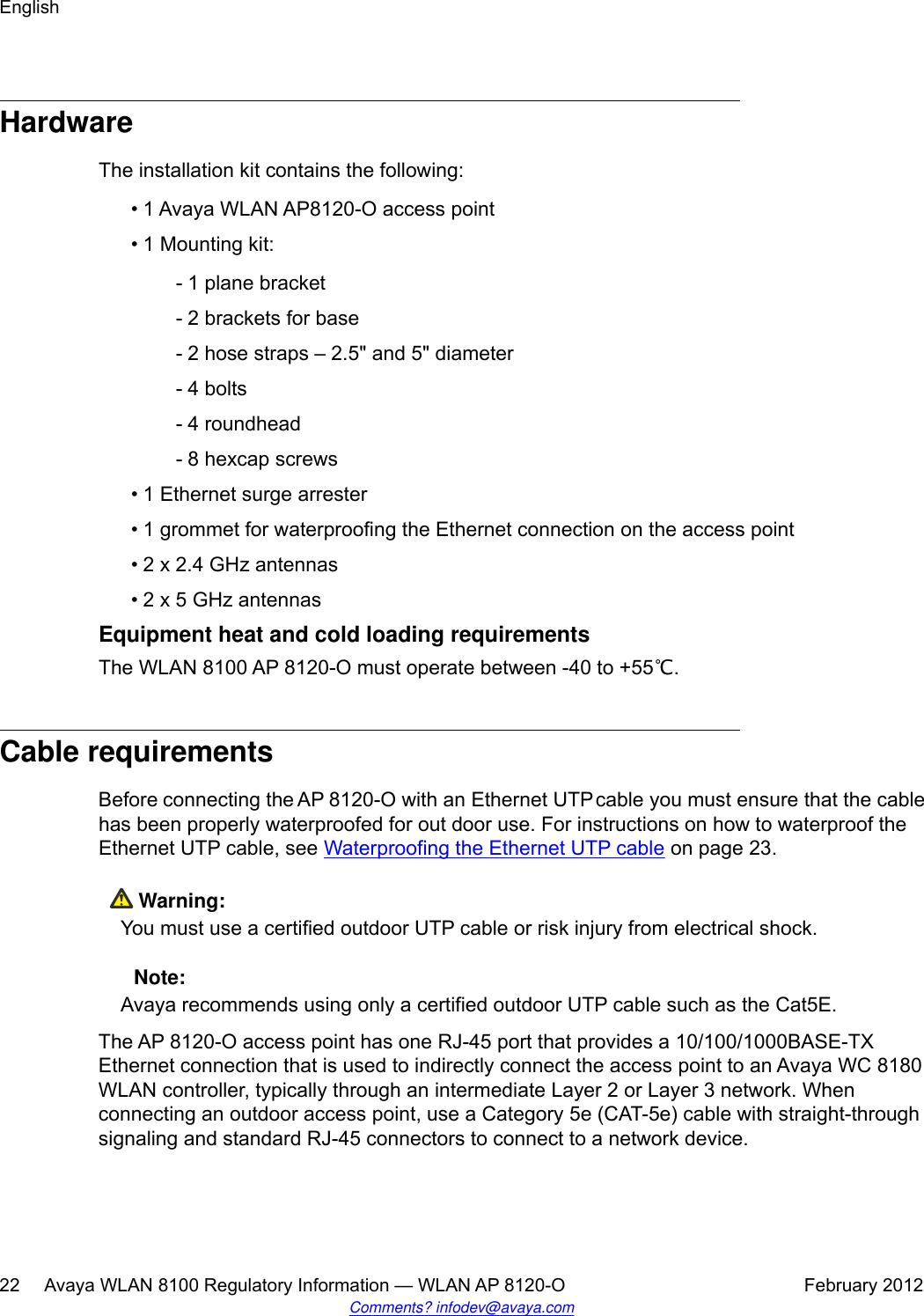
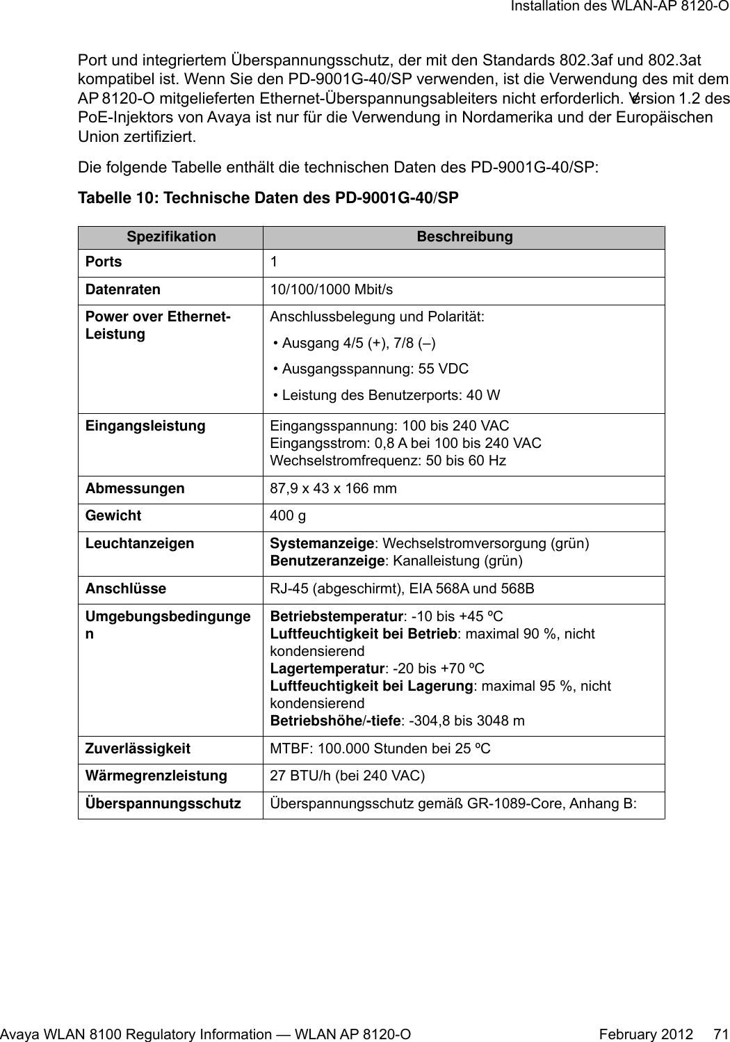
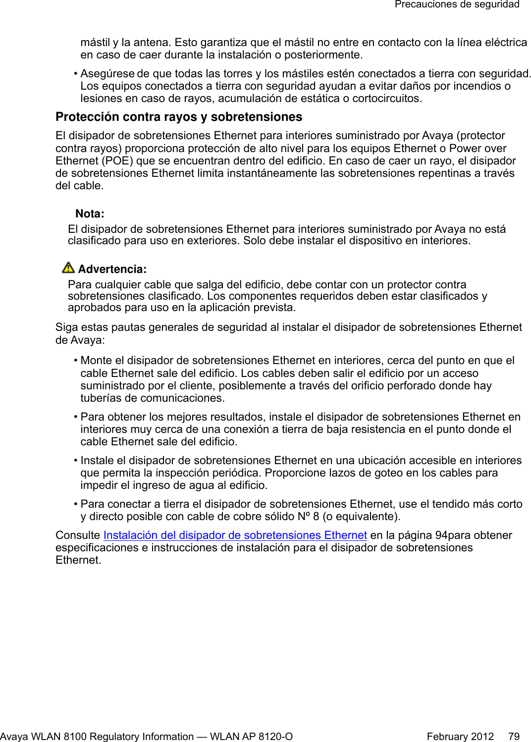
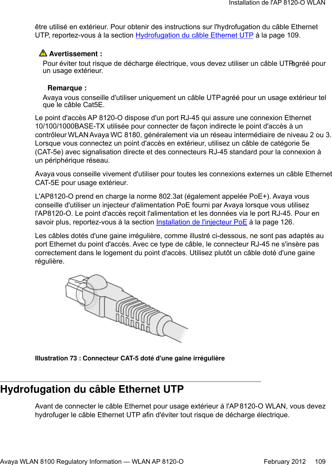
![Especificação Descrição• ± 1000 V/100 A a 10/1000 [μS] forma de onda• ± 2500 V/500 A a 2/10 [μS] forma de onda• ± 1000 V/25 A a 10/360 [μS] forma de ondaPor Que e Quando Desempenhar Esta TarefaPara instalar o PoE (Power over Ethernet) no WLAN AP 8120-O, faça o seguinte:Procedimento1. Antes de conectar o adaptador PoE ao WLAN AP 8120-O, é necessário aterrar oPoE primeiro. Para aterrar e conectar o PoE ao WLAN AP 8120-O, faça o seguinte:a. Conecte uma extremidade do fio de aterramento verde à haste de aterramentode cobre projetada na parte inferior do PoE.b. Conecte a outra extremidade do fio de aterramento a um aterramento de soloaceitável.2. Conecte o plugue fornecido à tomada do plugue de três entradas na parte inferiordo adaptador PoE.Figura 117: Haste de aterramento de cobre no PoE3. Conecte a outra extremidade a uma tomada CA que esteja funcionando.4. Insira uma extremidade de um cabo Ethernet na porta DATA IN do adaptadorPoE.Instalação do WLAN AP 8120-OAvaya WLAN 8100 Regulatory Information — WLAN AP 8120-O February 2012 155](https://usermanual.wiki/Senao-Networks/AP8120-O/User-Guide-1663909-Page-155.png)