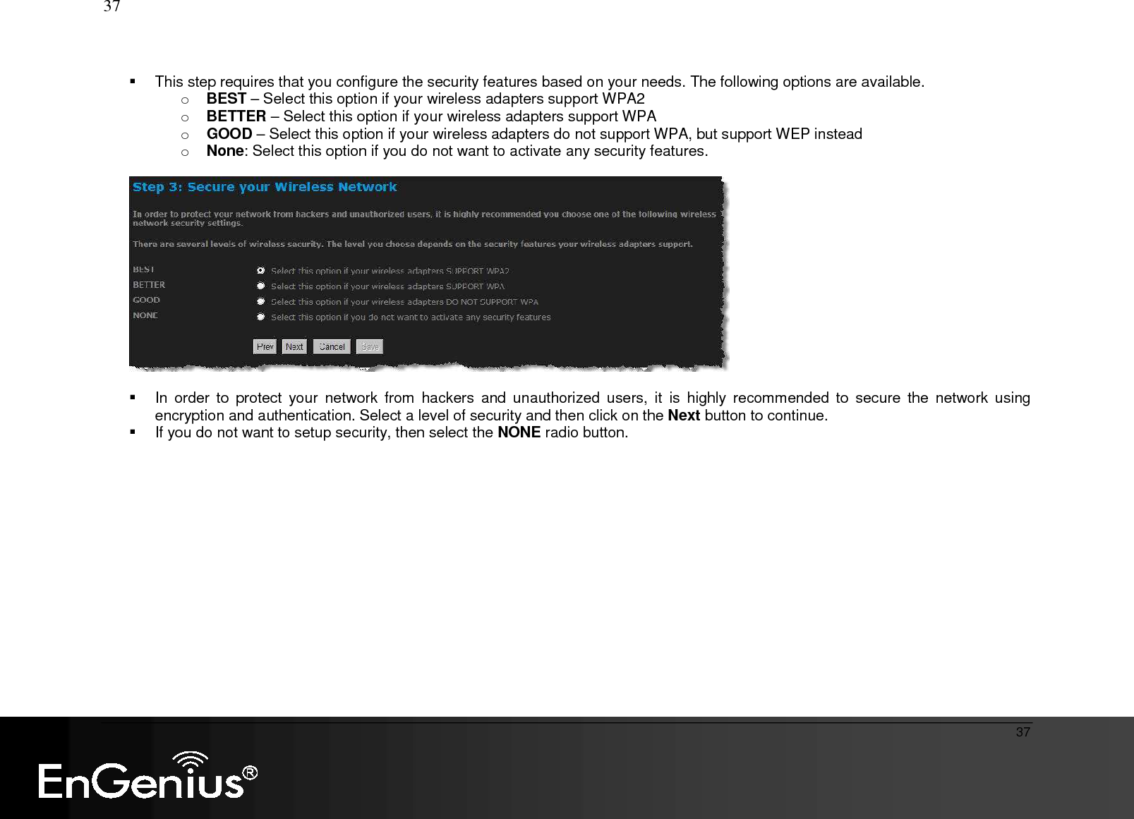
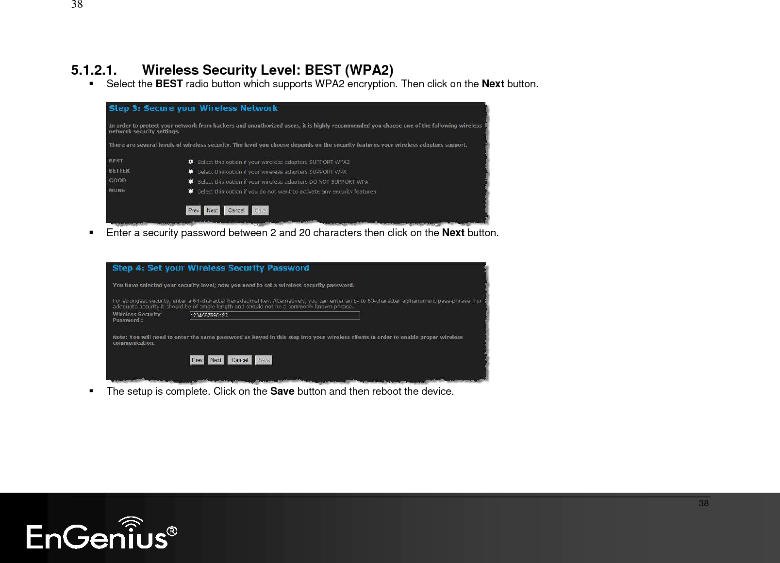
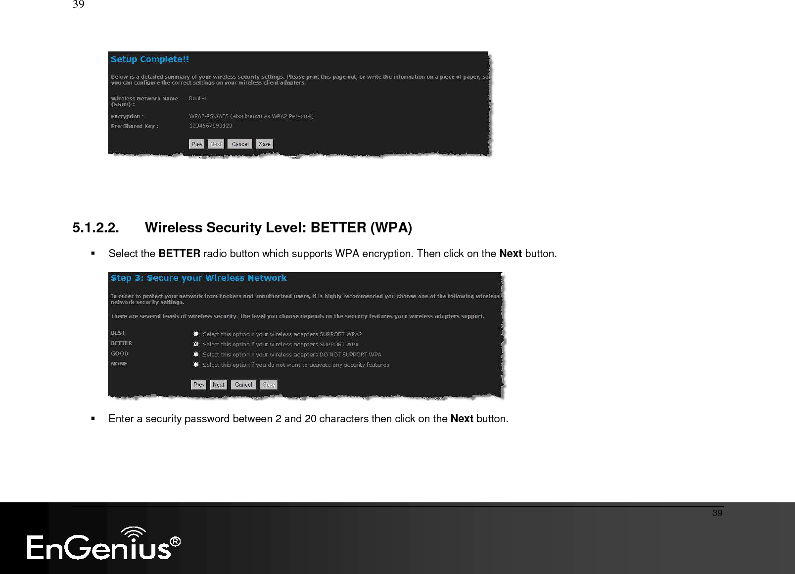
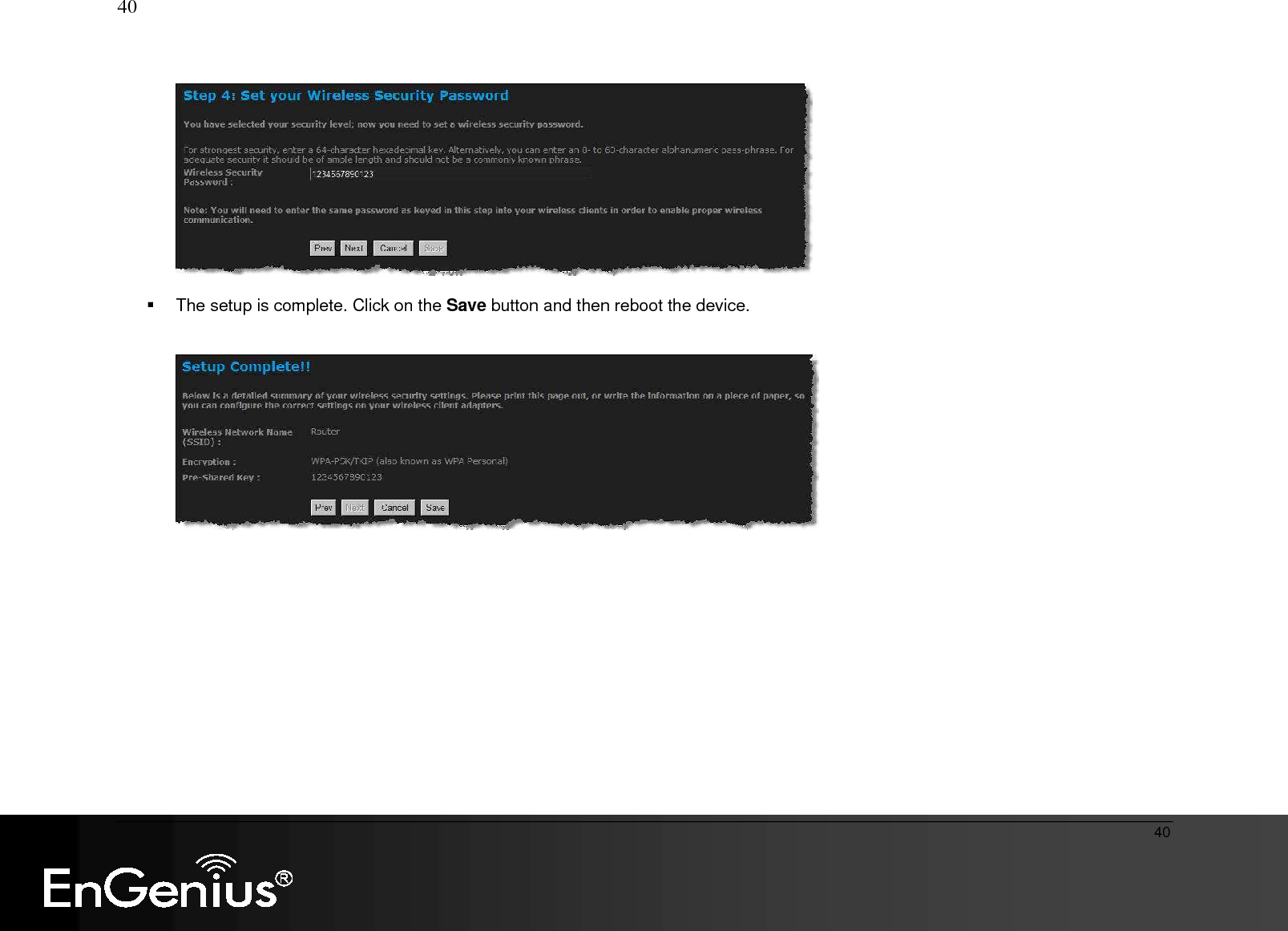
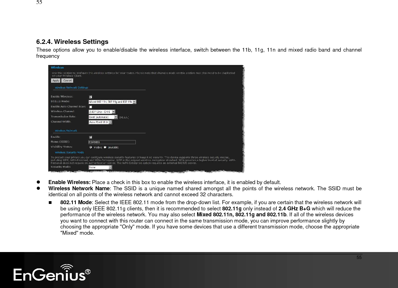
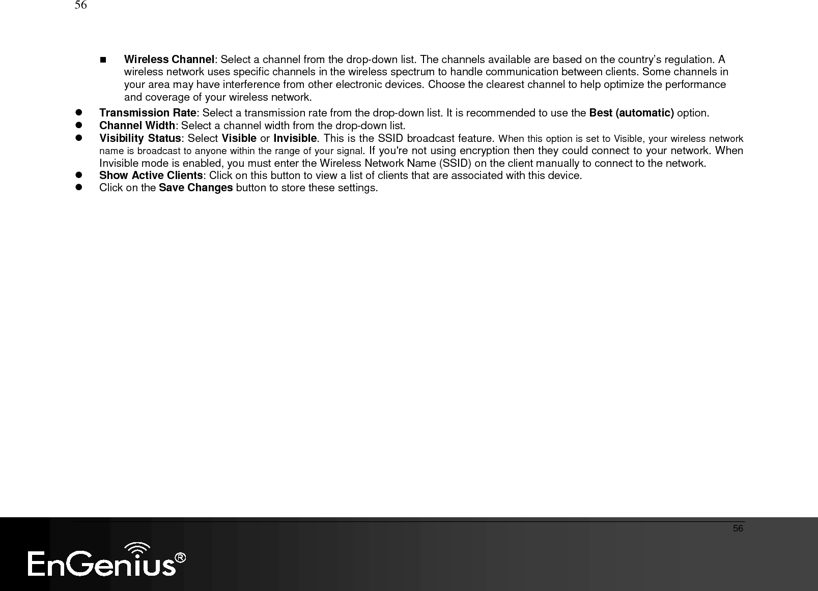
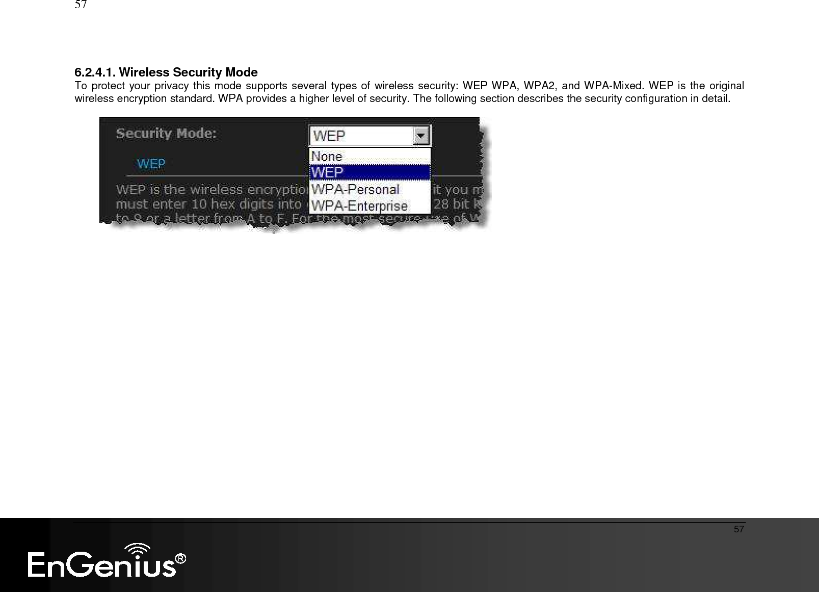
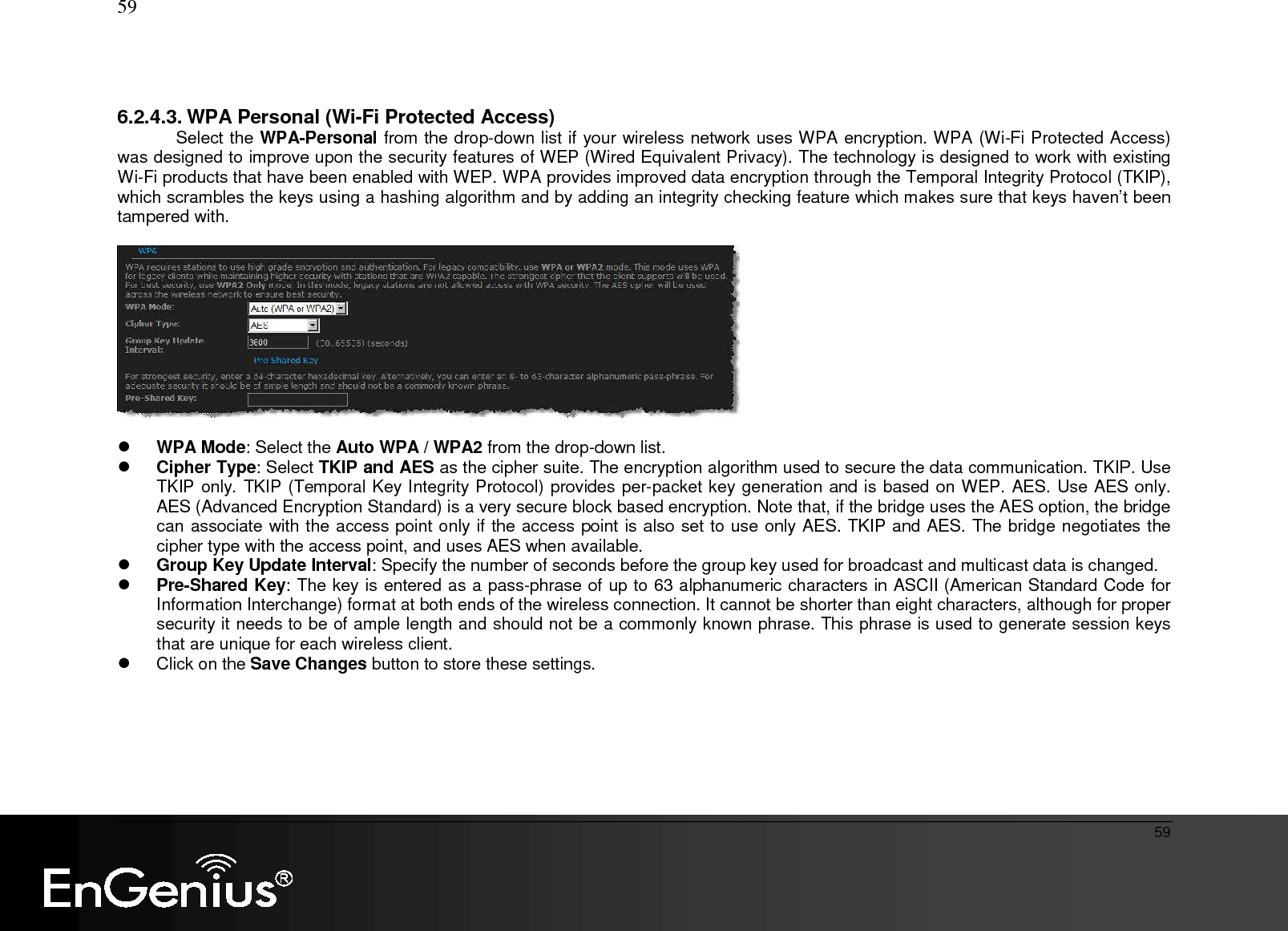
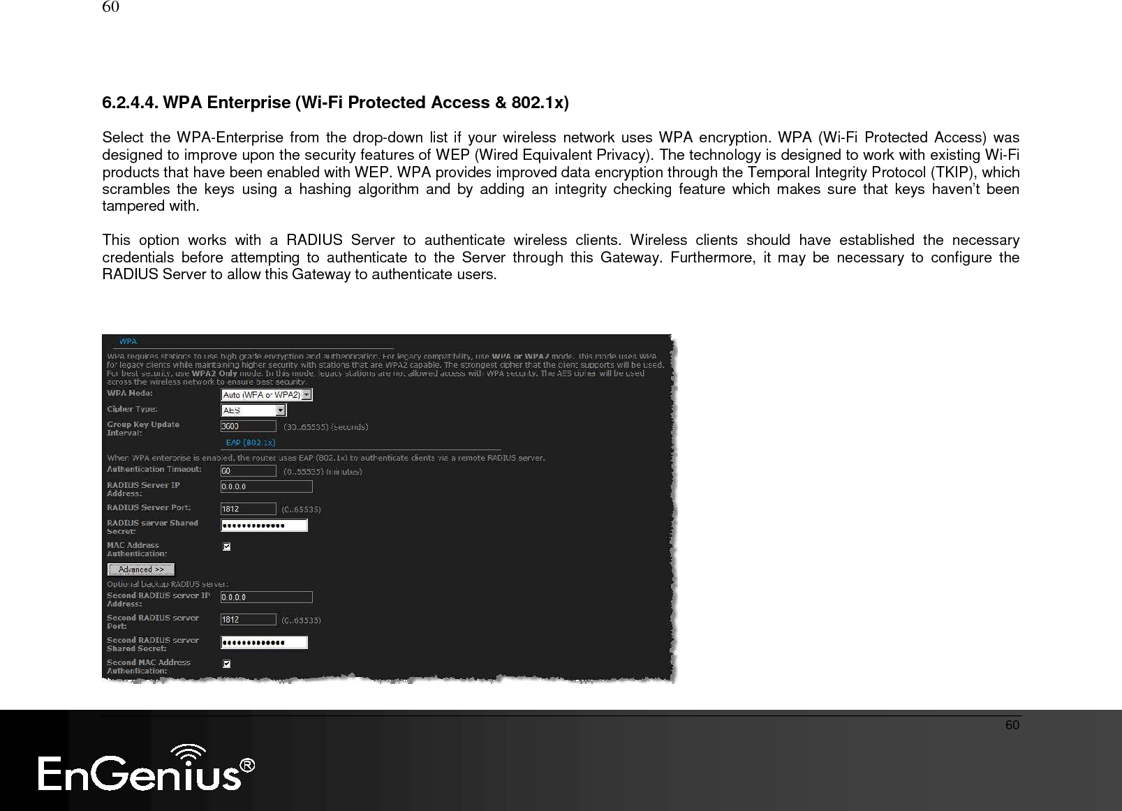
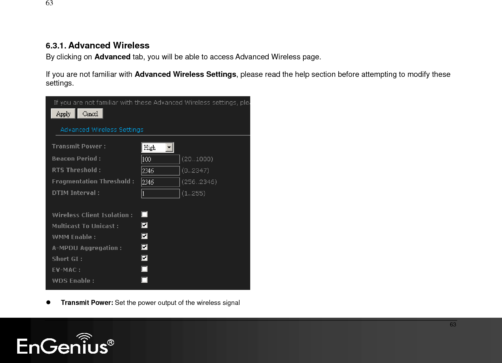
Senao Networks SR9855G Wireless 300N Gigabit Gaming Router User Manual ESR9855G UM 20100125
Senao Networks, Inc. Wireless 300N Gigabit Gaming Router ESR9855G UM 20100125
UserManual.wiki
>
Senao Networks
>
SR9855G User Manual
>
Manual Part 1
Contents
1.
Manual Part 1
2.
Manual Part 2
Manual Part 1
Navigation menu
Upload a User Manual
Namespaces
Wiki Guide
HTML
PDF
Info
Views
User Manual
Discussion / Help
Navigation

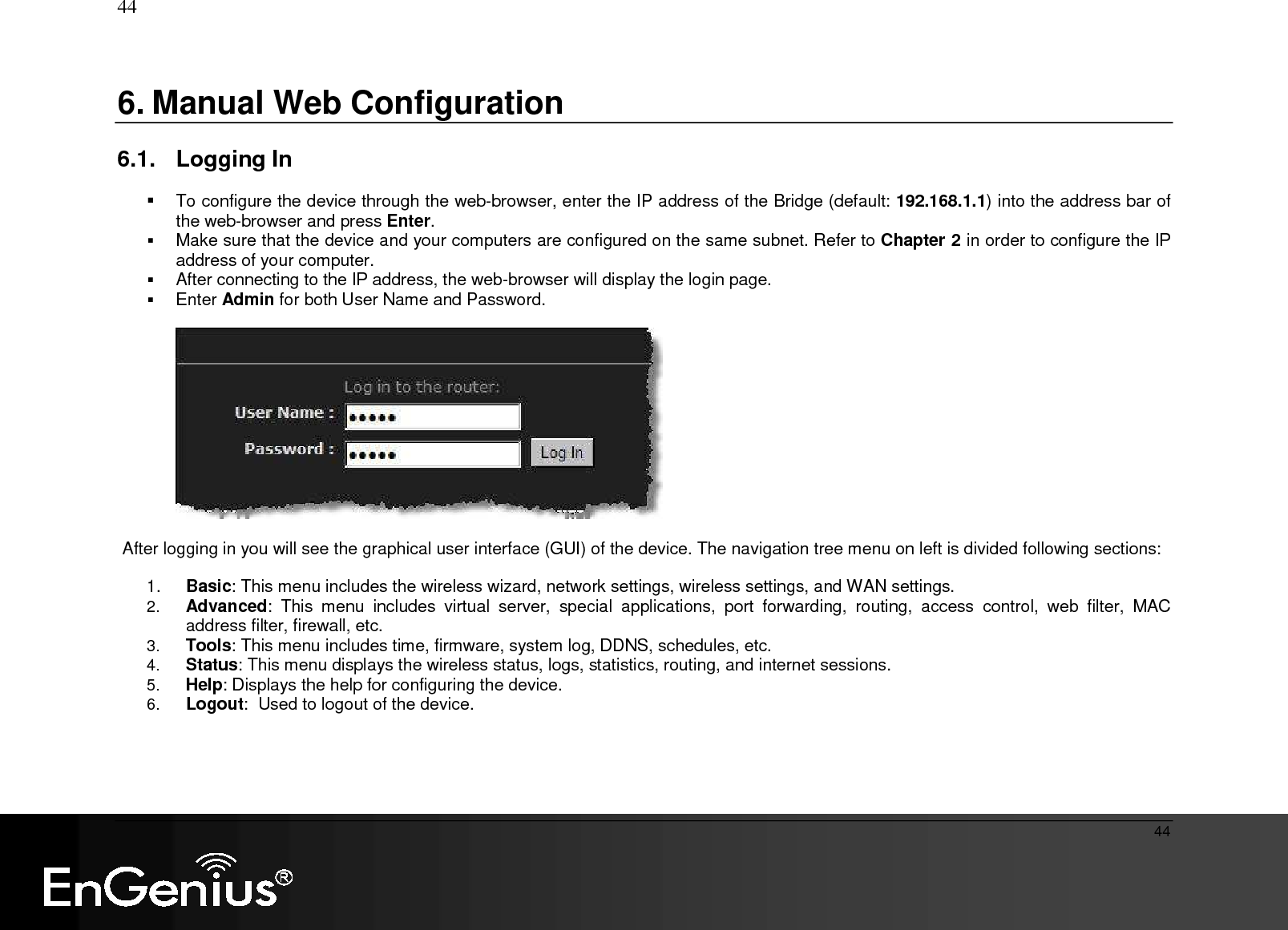
![20 20 3. Login To configure the device through the web-browser, enter the IP address of the device (default: 192.168.1.1) into the URL bar of the web-browser and press Enter. Make sure that the device and your computers are configured on the same subnet. Refer to previous chapter in order to configure the IP address of your computer. After connecting to the IP address, the web-browser will display the login page. Enter admin for both User Name and Password. Click on [Login] to enter the administration page..](https://usermanual.wiki/Senao-Networks/SR9855G.Manual-Part-1/User-Guide-1239897-Page-20.png)
![32 32 4.2.6. MAC Cloning MAC Address: specify the MAC address. Click on [Clone Your PC’s MAC address] button to enter the MAC address of your PC/laptop automatically.](https://usermanual.wiki/Senao-Networks/SR9855G.Manual-Part-1/User-Guide-1239897-Page-32.png)