Senao Networks SR9855G Wireless 300N Gigabit Gaming Router User Manual ESR9855G UM 20100125
Senao Networks, Inc. Wireless 300N Gigabit Gaming Router ESR9855G UM 20100125
Contents
- 1. Manual Part 1
- 2. Manual Part 2
Manual Part 1

User Manual
ESR9855G
Wireless 300N Gigabit Gaming Router
Gigabit & StreamEngine Support

2
2

3
3
Table of Contents
1.
INTRODUCTION........................................................................................................................................................................................... 7
1.1.
F
EATURES
&
B
ENEFITS
............................................................................................ 7
1.2.
P
ACKAGE
C
ONTENTS
.............................................................................................. 9
1.3.
S
AFETY
G
UIDELINES
............................................................................................... 9
1.4.
W
IRELESS
SOHO
R
OUTER
D
ESCRIPTION
................................................................10
1.5.
S
YSTEM
R
EQUIREMENTS
........................................................................................12
1.6.
A
PPLICATIONS
.......................................................................................................12
1.7.
N
ETWORK
C
ONFIGURATION
....................................................................................14
a)
Ad-hoc (peer-to-peer) Mode........................................................................................................................................................................................14
b)
Infrastructure Mode .....................................................................................................................................................................................................15
2.
UNDERSTANDING THE HARDWARE........................................................................................................................................................ 16
2.1.
H
ARDWARE
I
NSTALLATION
......................................................................................16
2.2.
W
ALL
M
OUNTING
...................................................................................................17
2.3.
IP
A
DDRESS
C
ONFIGURATION
.................................................................................18
3.
LOGIN ........................................................................................................................................................................................................ 20
4.
INTERNET SETTINGS................................................................................................................................................................................ 21
4.1.
I
NTERNET
C
ONNECTION
T
YPE
.................................................................................22
4.1.1.
DHCP Connection (Dynamic IP Address)........................................................................................................................................ 23
4.1.2.
PPPoE (Point-to-Point Protocol over Ethernet)................................................................................................................................ 24
4.1.3.
PPTP (Point-to-Point Tunneling Protocol) ....................................................................................................................................... 26
4.1.4.
Static IP Address Configuration ...................................................................................................................................................... 28
4.2.
O
THER
I
NTERNET
S
ETTINGS
...................................................................................29
4.2.1.
RIP (Routing Information Protocol).................................................................................................................................................. 29
4.2.2.
DNS Settings.................................................................................................................................................................................. 30
4.2.3.
MTU Settings.................................................................................................................................................................................. 30
4.2.4.
WAN Ping....................................................................................................................................................................................... 31
4.2.5.
Multicast Streams ........................................................................................................................................................................... 31
4.2.6.
MAC Cloning .................................................................................................................................................................................. 32
5.
WIRELESS SETUP WIZARD...................................................................................................................................................................... 33
5.1.
W
IRELESS
N
ETWORK
W
IZARD
S
ETUP
......................................................................33
5.1.1.
Automatic Network Setup................................................................................................................................................................ 34

4
4
5.1.2.
Manual Network Setup.................................................................................................................................................................... 35
5.1.2.1.
Wireless Security Level: BEST (WPA2).............................................................................................................................................................38
5.1.2.2.
Wireless Security Level: BETTER (WPA)..........................................................................................................................................................39
5.1.2.3.
Wireless Security Level: GOOD (WEP 64/128-bit) ............................................................................................................................................41
5.1.2.4.
Wireless Security Level: None (Security Disabled)............................................................................................................................................ 43
6.
MANUAL WEB CONFIGURATION ............................................................................................................................................................. 44
6.1.
L
OGGING
I
N
...........................................................................................................44
6.2.
B
ASIC
...................................................................................................................45
6.2.1.
Internet Settings ............................................................................................................................................................................. 45
6.2.2.
Wizard Wireless.............................................................................................................................................................................. 45
6.2.3.
Network Settings ............................................................................................................................................................................ 46
6.2.3.1.
Bridge Mode ......................................................................................................................................................................................................46
6.2.3.2.
Router Mode......................................................................................................................................................................................................47
6.2.4.
Wireless Settings............................................................................................................................................................................ 55
6.2.4.1.
Wireless Security Mode .....................................................................................................................................................................................57
6.2.4.2.
WEP (Wired Equivalent Privacy) .......................................................................................................................................................................58
6.2.4.3.
WPA Personal (Wi-Fi Protected Access)...........................................................................................................................................................59
6.2.4.4.
WPA Enterprise (Wi-Fi Protected Access & 802.1x)..........................................................................................................................................60
6.3.
A
DVANCED
............................................................................................................62
6.3.1.
Advanced Wireless......................................................................................................................................................................... 63
6.3.2.
Virtual Server.................................................................................................................................................................................. 65
6.3.3.
Special Applications........................................................................................................................................................................ 67
6.3.4.
Port Forwarding.............................................................................................................................................................................. 68
6.3.5.
StreamEngine................................................................................................................................................................................. 70
6.3.6.
Routing........................................................................................................................................................................................... 74
6.3.7.
Access Control ............................................................................................................................................................................... 75
6.3.8.
Web Filter....................................................................................................................................................................................... 79
6.3.9.
MAC Address Filter......................................................................................................................................................................... 80
6.3.10.
Firewall....................................................................................................................................................................................... 81
6.3.11.
Inbound Filter ............................................................................................................................................................................. 85
6.3.12.
WISH ......................................................................................................................................................................................... 86
6.3.13.
Wi-Fi Protected Setup................................................................................................................................................................. 88
6.3.14.
Advanced Network (UPNP, WAN Ping…) ................................................................................................................................... 89
6.4.
T
OOLS
..................................................................................................................91
6.4.1.
Time Zone Setting .......................................................................................................................................................................... 92
6.4.2.
System ........................................................................................................................................................................................... 93
6.4.2.1.
Save To Local Hard Drive..................................................................................................................................................................................94

5
5
6.4.2.2.
Load From Local Hard Drive..............................................................................................................................................................................94
6.4.2.3.
Restore To Factory Default................................................................................................................................................................................95
6.4.2.4.
Reboot the device.............................................................................................................................................................................................. 96
6.4.3.
Firmware Upgrade.......................................................................................................................................................................... 97
6.4.4.
System Logs................................................................................................................................................................................... 98
6.4.5.
Dynamic DNS................................................................................................................................................................................. 99
6.4.6.
System Check ...............................................................................................................................................................................100
6.4.7.
Schedules......................................................................................................................................................................................101
6.5.
S
TATUS
..............................................................................................................102
6.5.1.
Wireless Status..............................................................................................................................................................................103
6.5.2.
Logs Status ...................................................................................................................................................................................104
6.5.3.
Statistics........................................................................................................................................................................................105
6.5.4.
WISH Session Status.....................................................................................................................................................................106
6.5.5.
Routing..........................................................................................................................................................................................108
6.5.6.
Internet Session Status..................................................................................................................................................................109
6.5.7.
Firewall.......................................................................................................................................................................................... 111
APPENDIX A – GLOSSARY ..............................................................................................................................................................................112
8.......................................................................................................................................................................................................................................... 113
A......................................................................................................................................................................................................................................... 113
B......................................................................................................................................................................................................................................... 114
C......................................................................................................................................................................................................................................... 115
D......................................................................................................................................................................................................................................... 115
E......................................................................................................................................................................................................................................... 117
F.......................................................................................................................................................................................................................................... 117
G......................................................................................................................................................................................................................................... 118
H......................................................................................................................................................................................................................................... 118
I........................................................................................................................................................................................................................................... 119
J.......................................................................................................................................................................................................................................... 120
K.........................................................................................................................................................................................................................................120
L.......................................................................................................................................................................................................................................... 121
M.........................................................................................................................................................................................................................................121
N.........................................................................................................................................................................................................................................122
O.........................................................................................................................................................................................................................................123
P.........................................................................................................................................................................................................................................123
Q.........................................................................................................................................................................................................................................124
R.........................................................................................................................................................................................................................................124
S.........................................................................................................................................................................................................................................125
T.......................................................................................................................................................................................................................................... 126
U.........................................................................................................................................................................................................................................126

6
6
V.........................................................................................................................................................................................................................................127
W........................................................................................................................................................................................................................................ 127
X.........................................................................................................................................................................................................................................128
Y.........................................................................................................................................................................................................................................128
APPENDIX C – FCC INTERFERENCE STATEMENT.........................................................................................................................................129

7
7
1. Introduction
The Wireless-N Gigabit Router is a 802.11n compliant device that delivers up to 6x faster speeds than 802.11g while staying backward
compatible with 802.11g and 802.11b devices.
It is not only a Wireless Access Point, which lets you connect to the network without wires. There's also a built-in 4-port full-duplex
10/100/1000 Gigabit Switch to connect your wired-Ethernet devices together. The Router function ties it all together and lets your whole
network share a high-speed cable or DSL Internet connection.
The Access Point built into the Router uses advanced MIMO (Multi-Input, Multi-Output) technology to transmit multiple steams of data in
a single wireless channel. The robust signal travels farther, maintaining wireless connections up to 3 times farther than standard
802.11g, eliminates dead spots and extends network range.
To protect the data and privacy, the Router can encode all wireless transmissions with 64/128-bit encryption. It can serve as your
network's DHCP Server, has a powerful SPI firewall to protect your PCs against intruders and most known Internet attacks, and
supports VPN pass-through. The router also provide easy configuration with the web browser-based configuration utility.
The incredible speed and QoS function of 802.11n Gigabit Router is ideal for media-centric applications like streaming video, gaming,
and VoIP telephony. It is designed to run multiple media-intense data streams through the network at the same time, with no
degradation in performance.
This chapter describes the features & benefits, package contents, applications, and network configuration.
1.1. Features & Benefits
Features Benefits
High Speed Data Rate Up to 300Mbps Capable of handling heavy data payloads such as MPEG video streaming
IEEE 802.11n Compliant and backward
compatible with 802.11b/g Fully interoperable with IEEE 802.11b/g/n devices
Four built-in 10/100/1000Mbps Gigabit
Switch Ports (Auto-Crossover) Scalability, able to extend your network

8
8
Supports DNS/ DDNS Lets users assign a fixed host and domain name to a dynamic Internet IP address.
Supports NAT (Network Address
Translation)/NAPT
Shares single Internet account and provides a type of firewall by hiding internal IP
addresses for keeping hacker out
Hide SSID Avoids unallowable users sharing bandwidth, increases efficiency of the network
Firewall supports Virtual Server
Mapping, DMZ, IP Filter, ICMP Blocking,
SPI
Avoids the attacks of Hackers or Viruses from Internet
Support 802.1x authenticator, 802.11i
(WPA/WPA2, AES), VPN pass-thru
mechanisms
Provide mutual authentication (Client and dynamic encryption keys to enhance
security
WDS (Wireless Distribution System) Make wireless AP and Bridge mode simultaneously as a wireless repeater
Universal Plug and Play (UPnP™) Works with most Internet gaming and instant messaging applications for automatic
Internet access
Filter Scheduling The filter can be scheduled by days, hours or minutes for easy management
Real time alert The detection of a list for Hacker log-in information
Web configuration Helps administrators to remotely configure or manage the Router via Telnet/Web-
browser

9
9
1.2. Package Contents
Open the package carefully, and make sure that none of the items listed below are missing. Do not discard the packing materials, in
case of return; the unit must be shipped in its original package.
Wireless Gaming Router x 1
Power Adapter x 1
3dBi 2.4GHz Dipole Antennas x 2
CD-ROM with User Manual x 1
Quick Guide x 1
1.3. Safety Guidelines
In order to reduce the risk of fire, electric shock and injury, please adhere to the following safety guidelines.
Carefully follow the instructions in the User Manual and also follow all instruction labels on this device.
Except for the power adapter supplied, this device should not be connected to any other adapters except the supplied one.
Do not spill liquid of any kind on this device.
Do not place the device on an unstable stand or table. .
Do not expose this unit to direct sunlight.
Do not place any hot devices close to the device, as they may degrade or cause damage to the unit.
Do not place any heavy objects on top of the device.
Do not use liquid cleaners or aerosol cleaners. Use a soft dry cloth for cleaning.
10
10
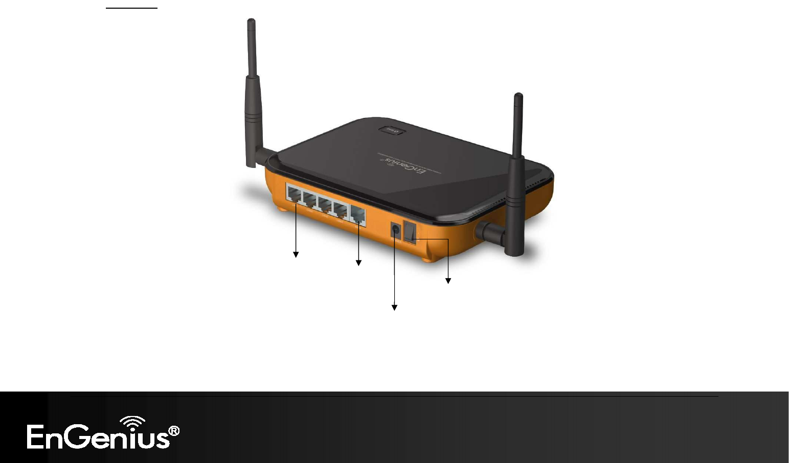
1.4. Wireless SOHO Router Description
Rear
Panel
Power Switch
LAN Ports
WAN / Internet
Port
Power
11
11
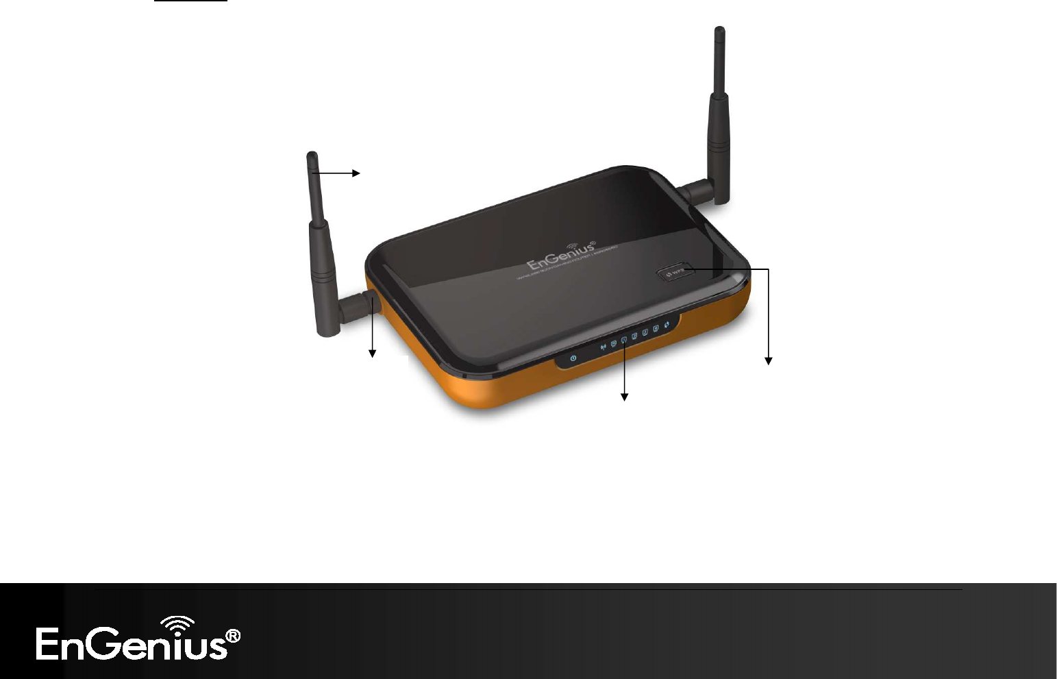
Front
Panel
WPS button
LED panel
Antenna
Antenna
Connector

12
12
Parts Description
LAN Ports (1 – 4) Use an Ethernet cable to connect each port to a computer on your Local Area Network (LAN).
WAN Port Use an Ethernet cable to connect this port to your WAN router.
Antenna Connector Interface for the antennas.
LAN LED This LED will light up once an Ethernet cable is connected to one of the LAN ports.
WAN LED This LED will light up once an Ethernet cable is connected to WAN (Internet) port.
WLAN LED This LED will light up once the RF (wireless LAN) feature is enabled
Power LED This LED will light up once the power cable is connected to the DC connector.
WPS button 1- 5 seconds: activates WPS
6-10 seconds: reboot
11~ seconds: reset to default
Power Switch Turn on or off the device
1.5. System Requirements
The following are the minimum system requirements in order to configure the device.
PC/AT compatible computer with an Ethernet interface.
Operating system that supports HTTP web-browser
1.6. Applications
The wireless LAN products are easy to install and highly efficient. The following list describes some of the many applications made
possible through the power and flexibility of wireless LANs:
a) Difficult-to-wire environments
There are many situations where wires cannot be laid easily. Historic buildings, older buildings, open areas and across busy
streets make the installation of LANs either impossible or very expensive.
b) Temporary workgroups
Consider situations in parks, athletic arenas, exhibition centers, disaster-recovery, temporary offices and construction sites
where one wants a temporary WLAN established and removed.

13
13
c) The ability to access real-time information
Doctors/nurses, point-of-sale employees, and warehouse workers can access real-time information while dealing with
patients, serving customers and processing information.
d) Frequently changed environments
Show rooms, meeting rooms, retail stores, and manufacturing sites where frequently rearrange the workplace.
e) Small Office and Home Office (SOHO) networks
SOHO users need a cost-effective, easy and quick installation of a small network.
f) Wireless extensions to Ethernet networks
Network managers in dynamic environments can minimize the overhead caused by moves, extensions to networks, and
other changes with wireless LANs.
g) Wired LAN backup
Network managers implement wireless LANs to provide backup for mission-critical applications running on wired networks.
h) Training/Educational facilities
Training sites at corporations and students at universities use wireless connectivity to ease access to information,
information exchanges, and learning.

14
14
1.7. Network Configuration
To better understand how the wireless LAN products work together to create a wireless network, it might be helpful to depict a
few of the possible wireless LAN PC card network configurations. The wireless LAN products can be configured as:
a) Ad-hoc (or peer-to-peer) for departmental or SOHO LANs.
b) Infrastructure for enterprise LANs.
a) Ad-hoc (peer-to-peer) Mode
This is the simplest network configuration with several computers equipped with the PC Cards that form a wireless
network whenever they are within range of one another. In ad-hoc mode, each client is peer-to-peer, would only have
access to the resources of the other client and does not require an access point. This is the easiest and least
expensive way for the SOHO to set up a wireless network. The image below depicts a network in ad-hoc mode.
15
15
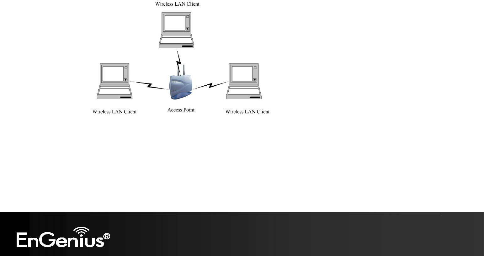
b) Infrastructure Mode
The infrastructure mode requires the use of an access point (AP). In this mode, all wireless communication between
two computers has to be via the AP. It doesn’t matter if the AP is stand-alone or wired to an Ethernet network. If used
in stand-alone, the AP can extend the range of independent wireless LANs by acting as a repeater, which effectively
doubles the distance between wireless stations. The image below depicts a network in infrastructure mode.

16
16
2. Understanding the Hardware
2.1. Hardware Installation
1. Place the device in an appropriate location after conducting a site survey.
2. Plug one end of the Ethernet cable into the LAN port of the device and another end into your PC/Notebook.
3. Plug one end of another Ethernet cable to WAN port of the device and the other end into you cable/DSL modem (Internet)
4. Insert the DC-inlet of the power adapter into the port labeled “POWER” and the other end into the power socket on the wall.
This diagram depicts the hardware configuration
WLAN Router
PC
Pow
er Outlet
Ethernet
AC/DC cable
Ethernet
Cable / DSL
Modem

17
17
2.2. Wall Mounting
Screw Dimension: 18mm x 5mm
You can mount the device on the wall. There are two mounting sockets on the bottom of the device. Please find a proper spot where
two nails can be applied. Finally, carefully mount the device onto the wall and make sure the nails are firmly locked on the mount
points.

18
18
2.3. IP Address Configuration
This device can be configured as a Bridge/Router or Access Point. The default IP address of the device is 192.168.1.1 In order to log
into this device, you must first configure the TCP/IP settings of your PC/Notebook.
1. In the control panel, double click Network Connections and then double click on the connection of your Network Interface Card
(NIC). You will then see the following screen.
19
19
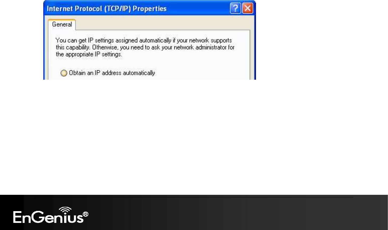
2. Select Internet Protocol (TCP/IP) and then click on the Properties button. This will allow you to configure the TCP/IP settings of
your PC/Laptop.
Select Obtain an IP address automatically radio button.
3. Click on the OK button to close this window, and once again to close LAN properties window.

20
20
3. Login
To configure the device through the web-browser, enter the IP address of the device (default: 192.168.1.1) into the URL bar of the
web-browser and press Enter.
Make sure that the device and your computers are configured on the same subnet. Refer to previous chapter in order to configure
the IP address of your computer.
After connecting to the IP address, the web-browser will display the login page. Enter admin for both User Name and Password.
Click on [Login] to enter the administration page..

21
21
4. Internet Settings
This device offers a quick and simple configuration through the wizard. This chapter describes how to use the wizard to configure the
WAN, LAN, and wireless settings. Please refer to Chapter 6 in order to configure the more advanced features of the device.
IMPORTANT NOTICE
The configuration wizard for each connection type is described below.
Click on the Internet Settings to begin the process.
Internet Settings Page contains various settings related to WAN / Internet service. Usually, you only need to
configure Internet Connection Type section to connect to the Internet. Unless your ISP specified otherwise,
please keep the default settings if you are unsure of the configuration. Please consult your local ISP for your
Internet Connection Type and account information.
22
22
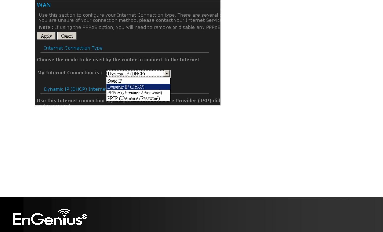
4.1. Internet Connection Type
Select your Internet service WAN type
This device supports several types of Internet / WAN connections:
o DHCP Connection (Dynamic IP address) – Choose this connection type if your ISP provides you the IP address. Most
cable modems use this type of connection.
o PPPoE (Poinit-to-Point Protocol over Ethernet) – Choose this option if your internet connection requires a user name
and password. Most DSL modems use this type of connection.
o PPTP (Point-to-Point Tunneling Protocol) – Choose this type of connection if your ISP requires to use PPTP. Your ISP
should provide you with a user name and password.
o Static IP address – Choose this option if you have a dedicated IP address.
Page content will change in accords to the Internet Connection option. Please consult your local ISP for the appropriate choice. The
following sections explain the supported Internet type.
23
23
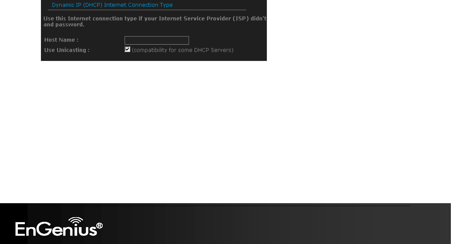
4.1.1. DHCP Connection (Dynamic IP Address)
The WAN interface can be configured as a DHCP Client in which the ISP provides the IP address to the device. This is also known as
Dynamic IP.
Host Name: this is optional if you need to specify the host name for this router.
Use Unicasting: This option is normally turned off, and should remain off as long as the WAN-side DHCP server correctly provides an IP
address to the router. However, if the router cannot obtain an IP address from the DHCP server, the DHCP server may be one that works
better with unicast responses. In this case, turn the unicasting option on, and observe whether the router can obtain an IP address. In this
mode, the router accepts unicast responses from the DHCP server instead of broadcast responses.
24
24
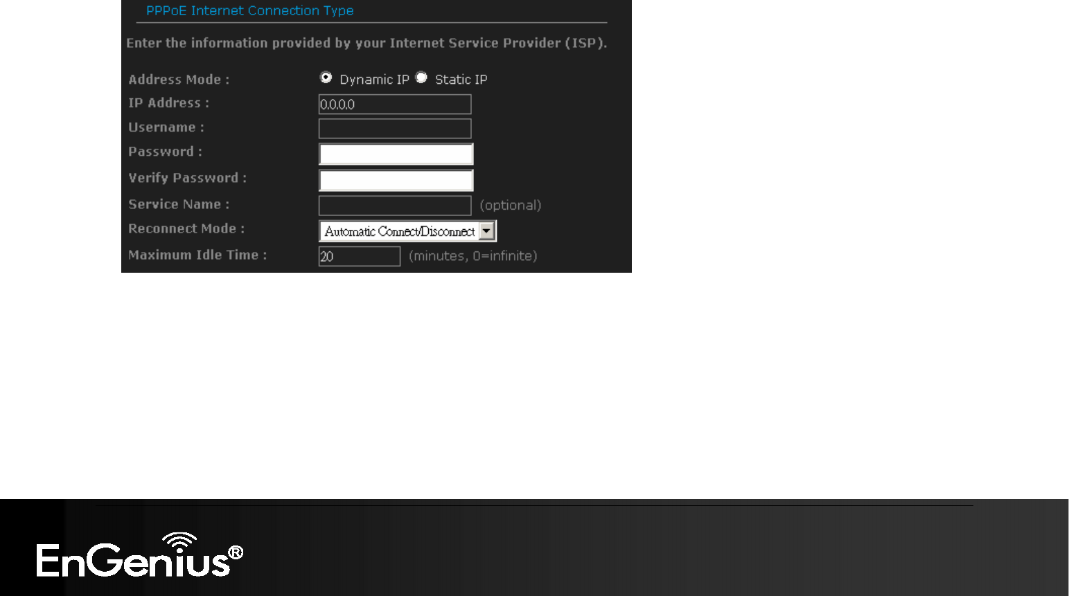
4.1.2. PPPoE (Point-to-Point Protocol over Ethernet)
The WAN interface can be configured as PPPoE. This type of connection is usually used for a DSL service and requires a
username and password to connect.
Address Mode: PPPoE can be used with a dynamic or static IP address. If you select the Dynamic IP radio button, then the IIP
address in the next field is not required. However, if you select the Static IP radio button, then the IP address in the next field is
required.
IP Address: Specify the IP address if the Static IP is selected.
User Name: Specify the username which is provided by your ISP.
Password: Specify the password which is provided by your ISP, and then verify it once again in the next field.
Verify Password: Enter the password again for verification
Service Name: Specify the name of the ISP. This is optional.
Reconnect Mode:
o Keep Connection: This option provides a continuous connection.

25
25
o Automatic Connect: This option provides an automatically connect.
o Manual Connect: This option provides a connection on demand.
Maximum Idle Time: Specify the maximum idle time (disconnect when device is idled over the specified period.
26
26
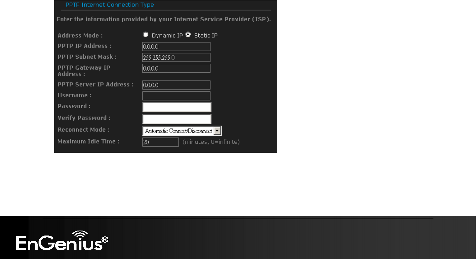
4.1.3. PPTP (Point-to-Point Tunneling Protocol)
PPTP (Point to Point Tunneling Protocol) uses a virtual private network to connect to your ISP. This method of connection requires
you to enter a username and password (provided by your ISP) to gain access to the Internet. The supported authentication
protocols are PAP and CHAP.
Address Mode: PPTP can be used with a dynamic or static IP address. If you select the Dynamic IP radio button, then the IIP
address in the next field is not required. However, if you select the Static IP radio button, then the IP address in the next field is
required.
PPTP IP Address: Specify the IP address
PPTP Subnet Mask: Specify the subnet Mask for the IP address.
PPTP Gateway IP Address: Specify the IP address of the PPTP gateway.

27
27
PPTP Server IP Address: If the PPTP Server’s IP address is different from the default gateway, then you may specify it here.
Usernname: Specify the user name which is provided by your ISP.
Password: Specify the password which is provided by your ISP, and then verify it once again in the next field.
Verify Password: enter the password again for verification
Reconnect Mode:
o Keep Connection: This option provides a continuous connection.
o Automatic Connect: This option provides an automatically connect.
o Manual Connect: This option provides a connection on demand.
Maximum Idle Time: Specify the maximum idle time (disconnect when device is idled over the specified period.
28
28
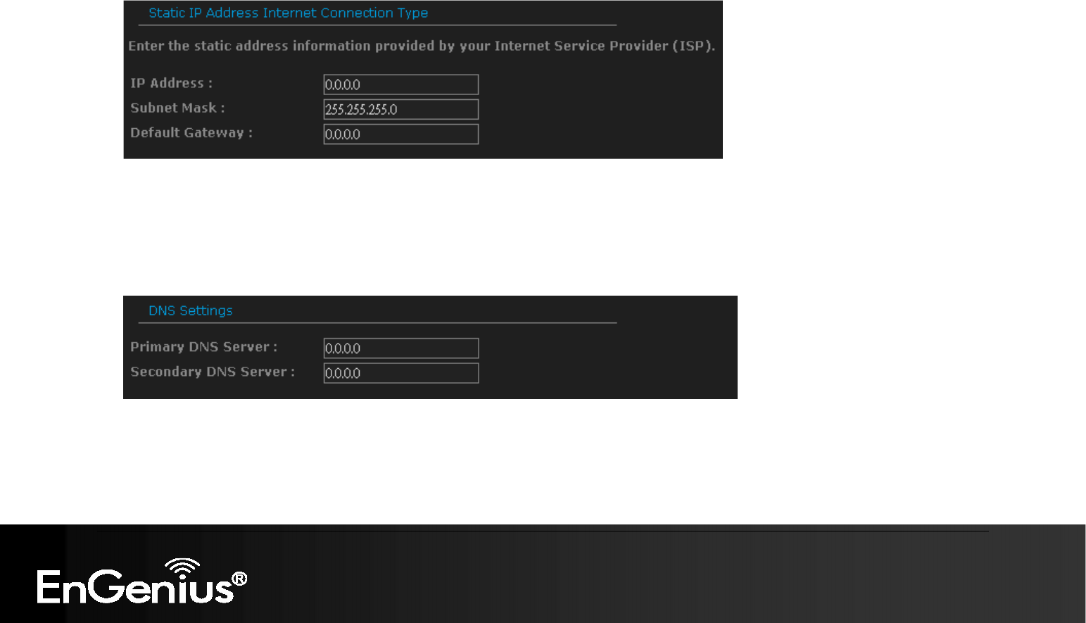
4.1.4. Static IP Address Configuration
In this type of connection, your ISP provides you with a dedicated IP address.
IP Address: Specify the IP address for the device, which is assigned by your ISP.
Subnet Mask: Specify the subnet mask for this IP address, which is assigned by your ISP.
Gateway Address: Specify the IP address of the default gateway, which is assigned by your ISP.
Usually, Static IP Address needs to specify DNS setting; please configure your DNS setting.
Primary / Secondary DNS Address: Specify the primary and secondary IP address, which is assigned by your ISP.
29
29
4.2. Other Internet Settings
IMPORTANT NOTICE
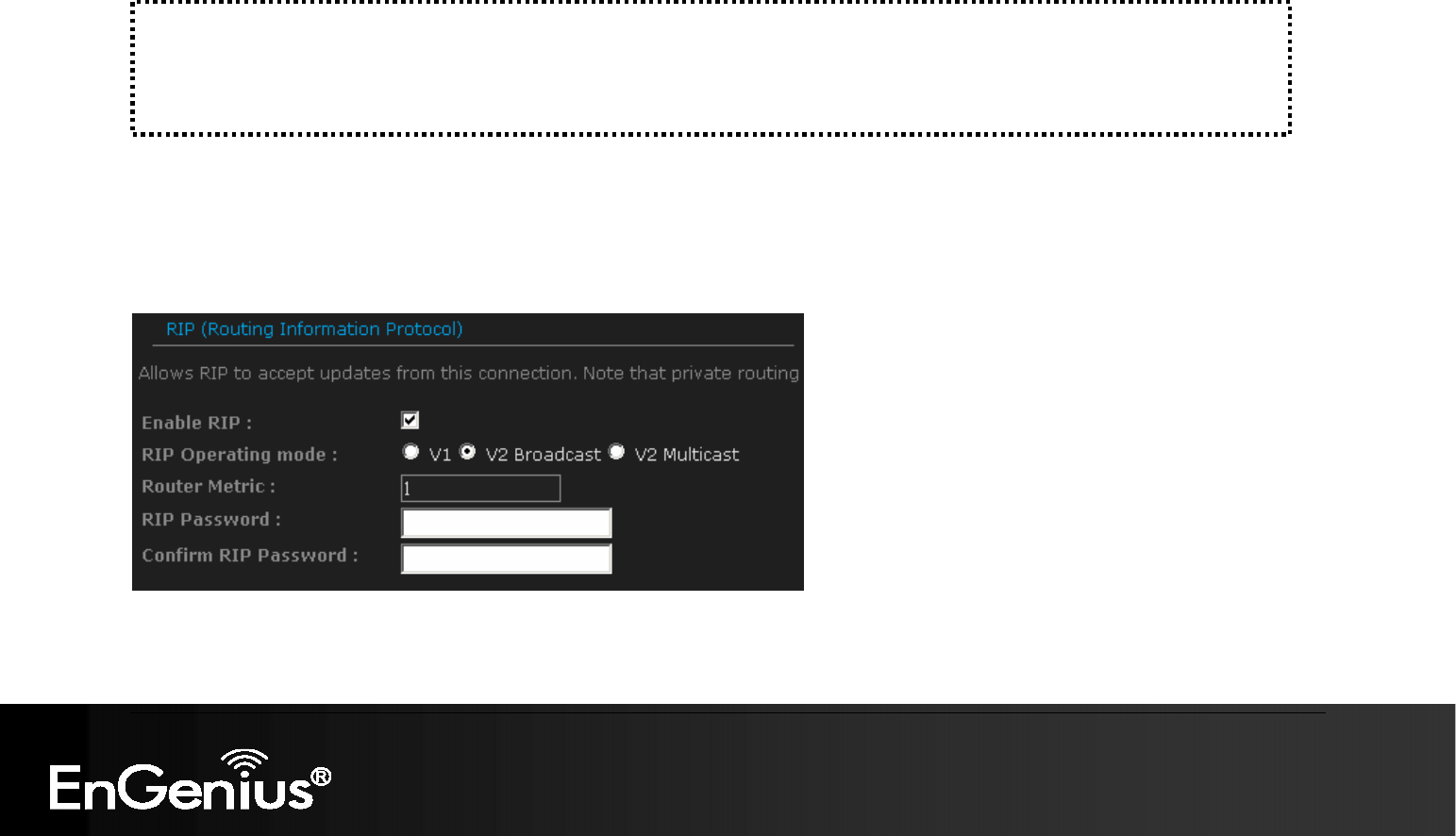
4.2.1. RIP (Routing Information Protocol)
This function allows RIP to accept updates from this connection. Note that private routing information is never sent to this
connection.
Internet Settings Page contains various settings related to WAN / Internet service. Usually, you only need to
configure Internet Connection Type section to connect to the Internet. Unless your ISP specified otherwise,
please keep the default settings if you are unsure of the configuration. Please consult your local ISP for your
Internet Connection Type and account information.
30
30
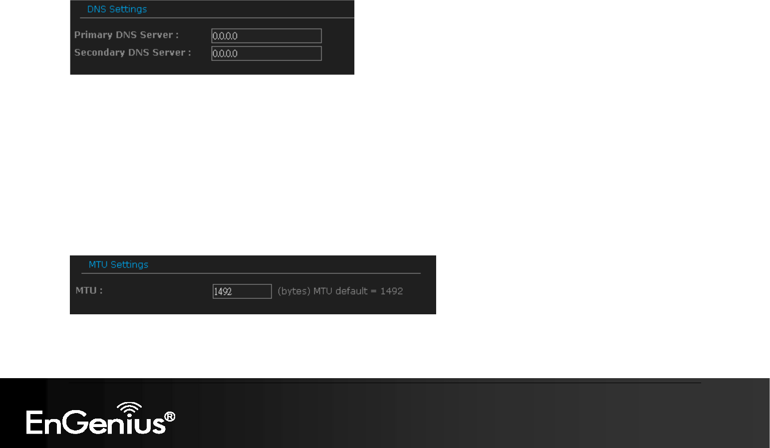
4.2.2. DNS Settings
Most of the ISP does not require user to specify DNS settings. In case where DNS needs to be specified you can change
the setting in this section.
4.2.3. MTU Settings
Most of the ISP does not require user to specify MTU settings. In case where MTU needs to be specified. You can change
the setting in this section.
MTU: The Maximum Transmission Unit (MTU) is a parameter that determines the largest packet size (in bytes) that the router will
send to the WAN. If LAN devices send larger packets, the router will break them into smaller packets. Ideally, you should set this to
match the MTU of the connection to your ISP. Typical values are 1500 bytes for an Ethernet connection and 1492 bytes for a PPPoE
connection. If the router's MTU is set too high, packets will be fragmented downstream. If the router's MTU is set too low, the router
will fragment packets unnecessarily and in extreme cases may be unable to establish some connections. In either case, network
performance can suffer.
31
31
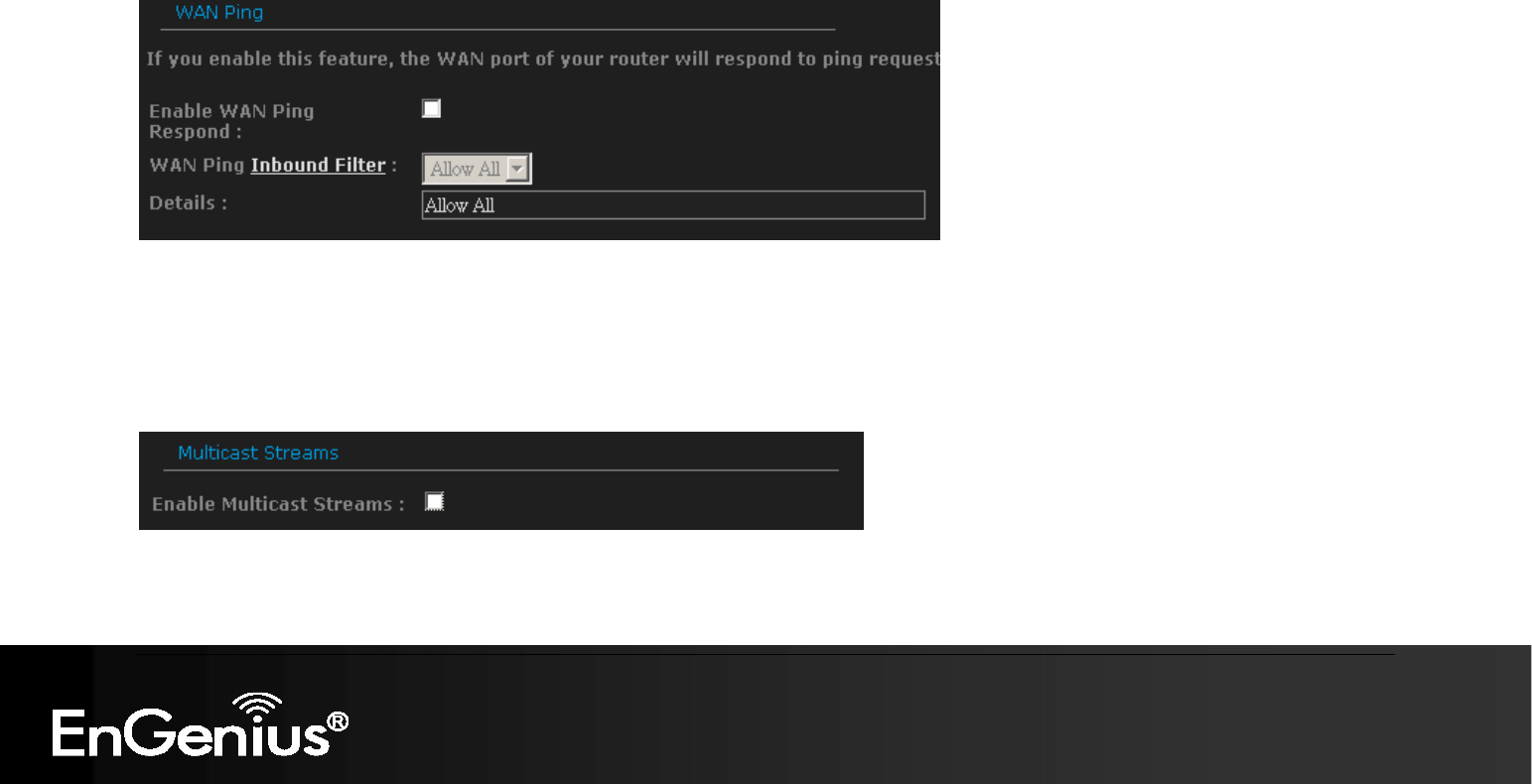
4.2.4. WAN Ping
If you enable this feature, the WAN port of your router will respond to ping requests from the Internet that are sent to the
WAN IP Address.
Enable WAN Ping Respond: checking the box.
You can specify the Inbound Filter and choose whether to Allow All or Deny All.
4.2.5. Multicast Streams
Enable Multicast Streams: checking the box if you have multicast streaming service on your local network.

32
32
4.2.6. MAC Cloning
MAC Address: specify the MAC address.
Click on [Clone Your PC’s MAC address] button to enter the MAC address of your PC/laptop automatically.
33
33
5. Wireless Setup Wizard
This wizard will guide you in the configuration of the wireless network settings such as the SSID and security (WEP/WPA).
.Please refer to Chapter 6 in order to configure more advanced features of the device
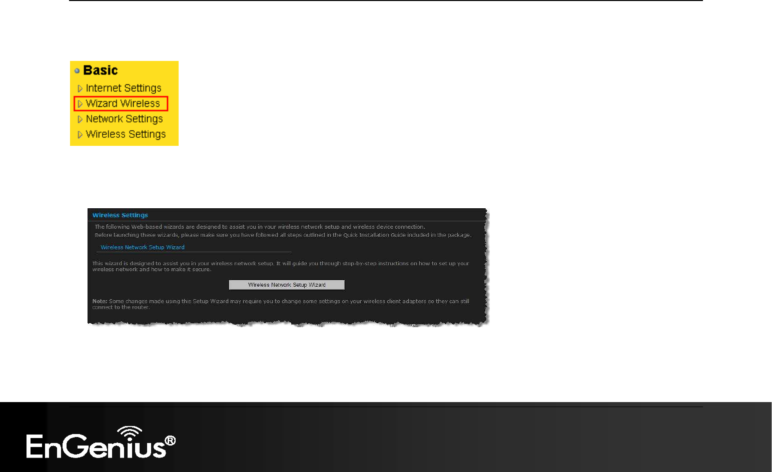
5.1. Wireless Network Wizard Setup
Click on the Wizard Wireless link under the Basic menu, and then click on the Wireless Network Setup Wizard button.
34
34
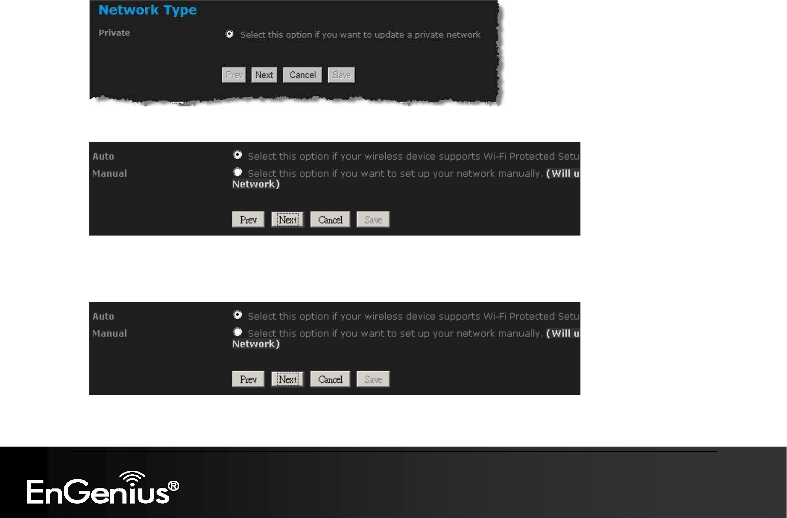
The wizard will inform you that there are two options: auto and manual.
5.1.1. Automatic Network Setup
If you select the Auto option, then the device will automatically configure the SSID and security mode.
Click on the Next button to continue.

35
35
The wizard has automatically configured the SSID and security mode for the device. Click on the Save button to complete the setup.
5.1.2. Manual Network Setup
If you select the Manual option, then you will be required to specify the SSID and select the appropriate network security.
Click on the Next button to continue.
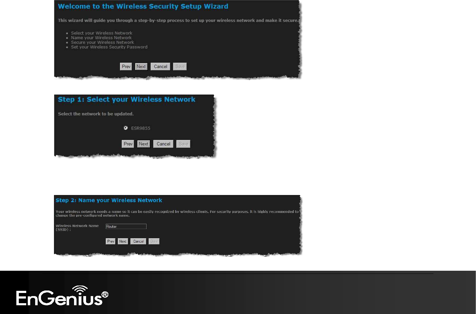
The wireless wizard will inform you that there are three major steps in the process.
o Name your wireless network
o Secure your wireless network
o Set your wireless security password
36
36
Click on the Next button to continue.
Specify the Wireless Network Name (SSID) for the device. The SSID is a unique named shared amongst all the points of the
wireless network. The SSID must be identical on all points of the wireless network and cannot exceed 32 characters. Click on the
Next button to continue.
37
37
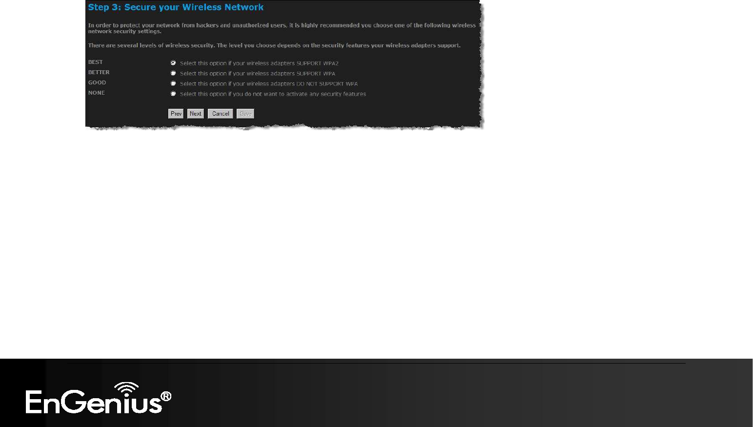
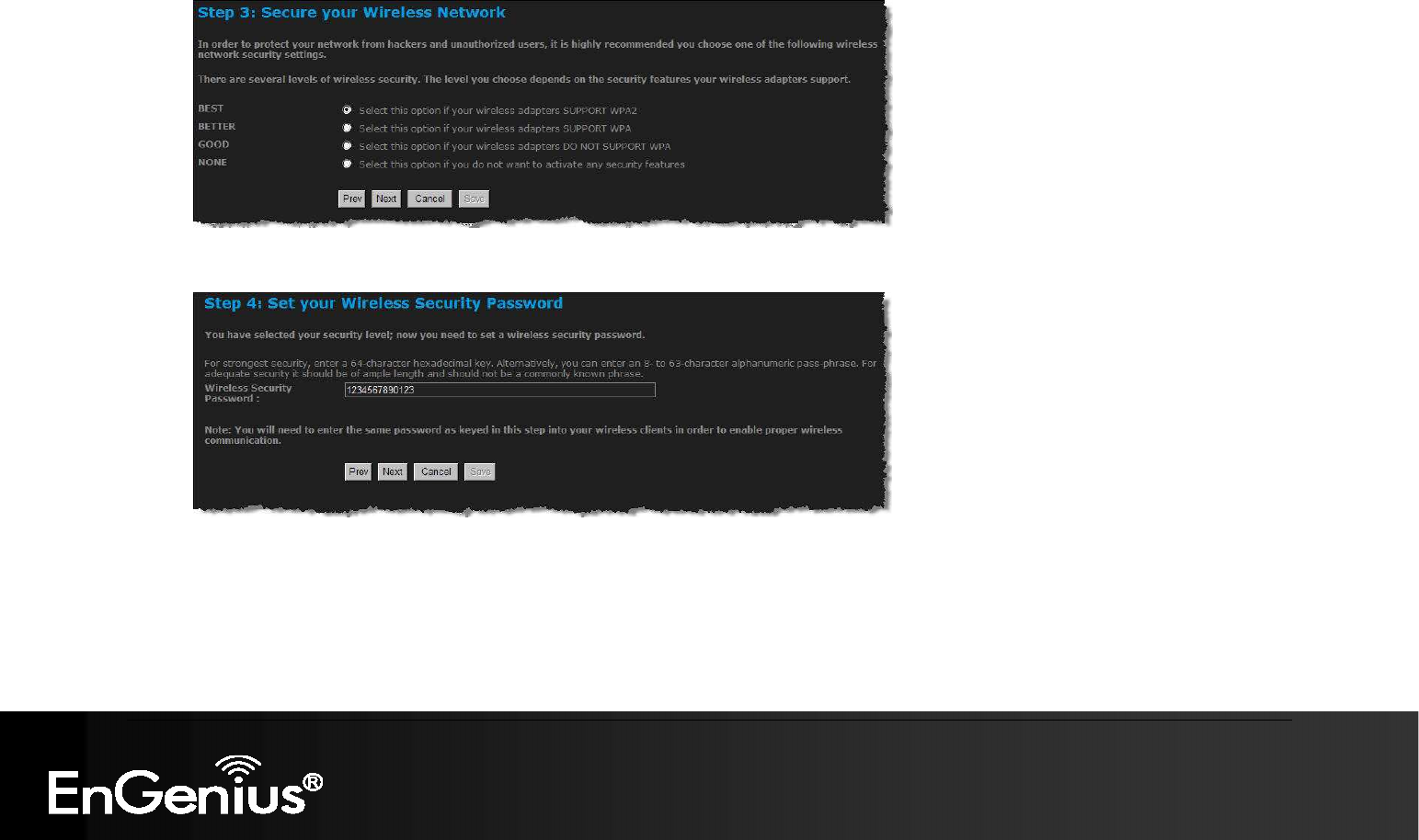
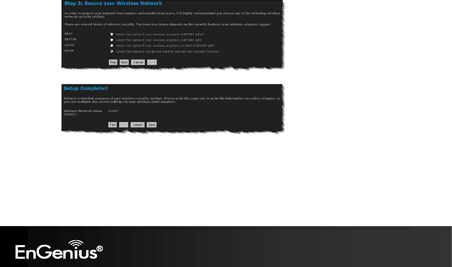
This step requires that you configure the security features based on your needs. The following options are available.
o BEST – Select this option if your wireless adapters support WPA2
o BETTER – Select this option if your wireless adapters support WPA
o GOOD – Select this option if your wireless adapters do not support WPA, but support WEP instead
o None: Select this option if you do not want to activate any security features.
In order to protect your network from hackers and unauthorized users, it is highly recommended to secure the network using
encryption and authentication. Select a level of security and then click on the Next button to continue.
If you do not want to setup security, then select the NONE radio button.
38
38
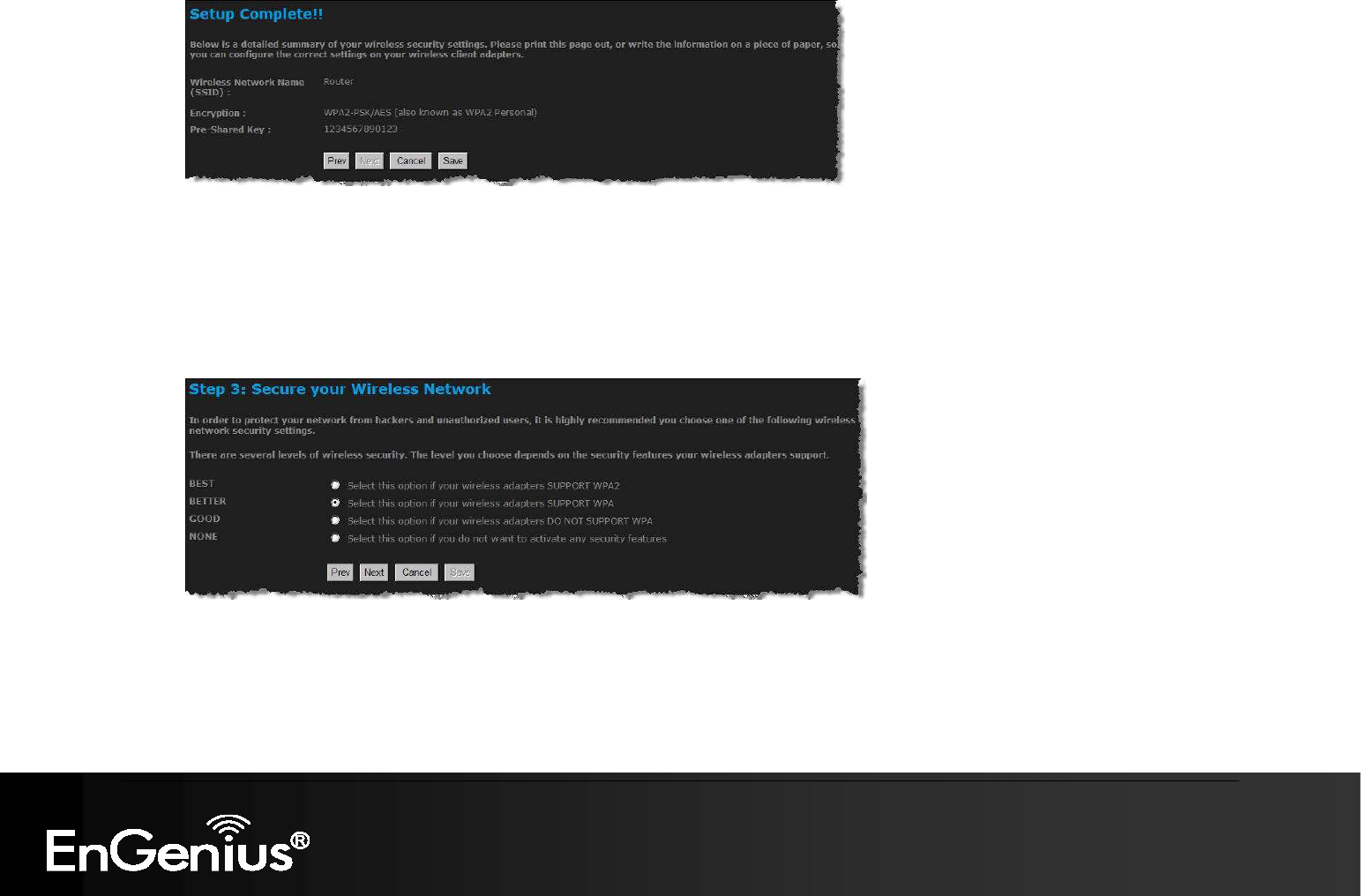
5.1.2.1. Wireless Security Level: BEST (WPA2)
Select the BEST radio button which supports WPA2 encryption. Then click on the Next button.
Enter a security password between 2 and 20 characters then click on the Next button.
The setup is complete. Click on the Save button and then reboot the device.
39
39
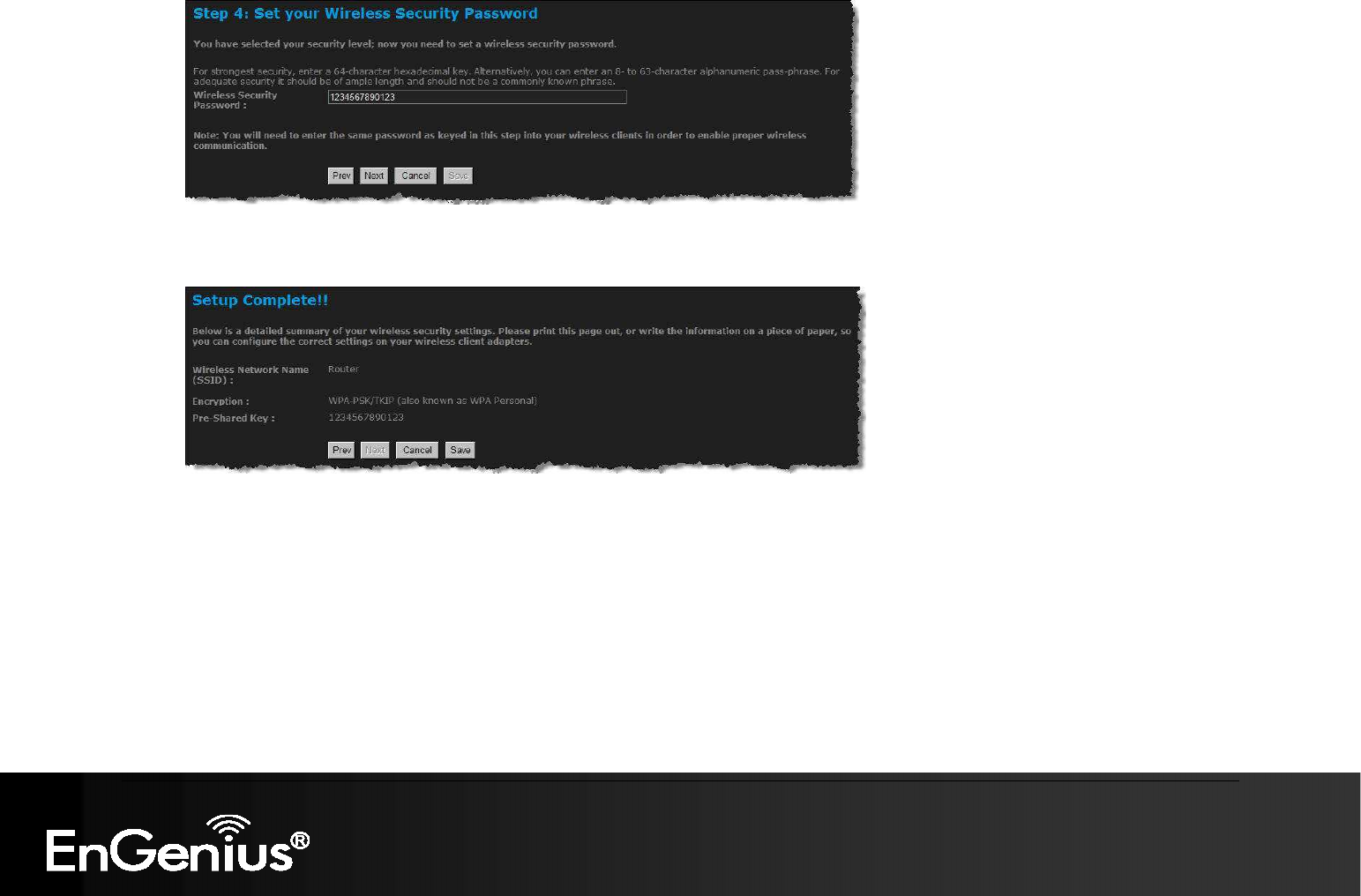
5.1.2.2. Wireless Security Level: BETTER (WPA)
Select the BETTER radio button which supports WPA encryption. Then click on the Next button.
Enter a security password between 2 and 20 characters then click on the Next button.
40
40
The setup is complete. Click on the Save button and then reboot the device.
41
41
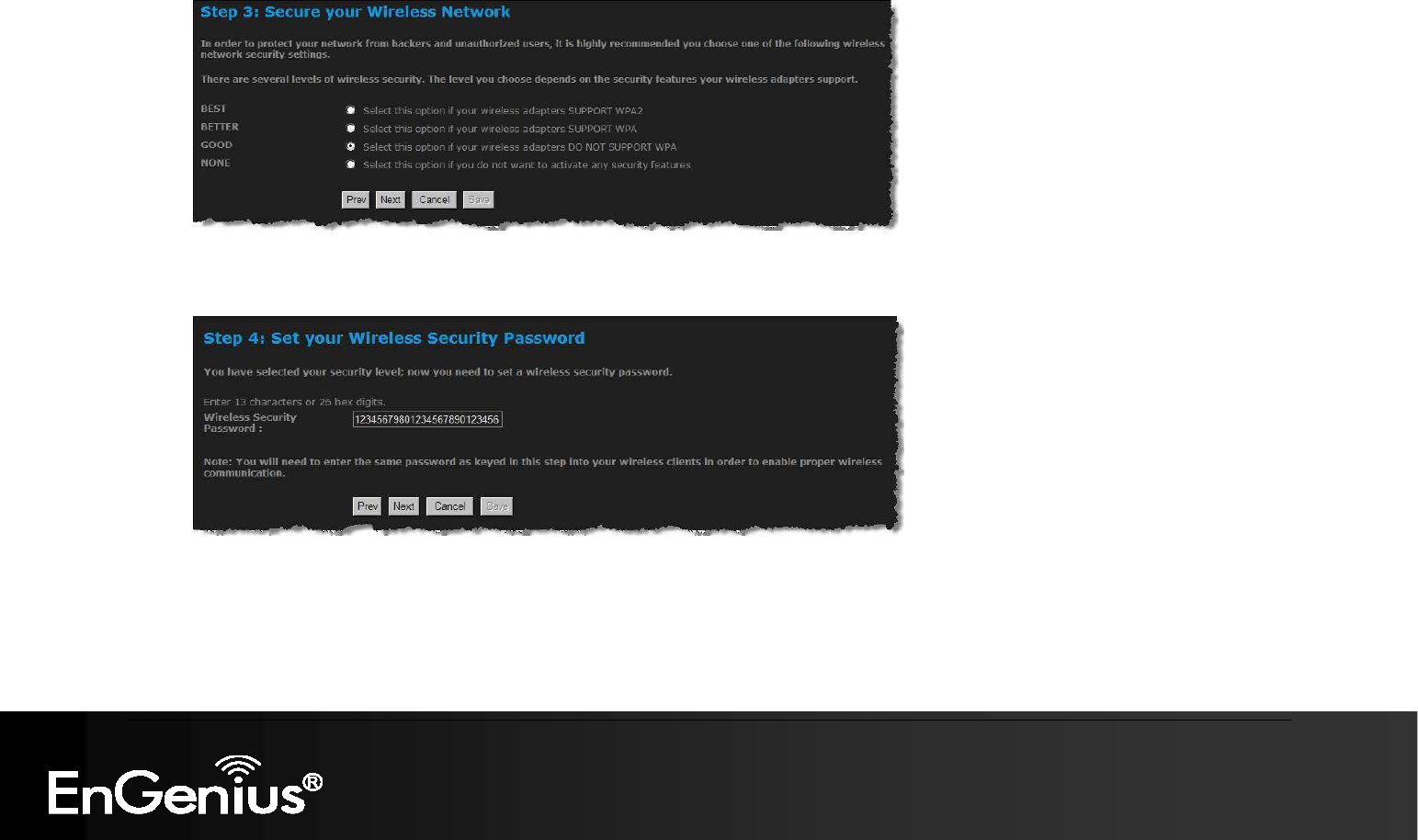
5.1.2.3. Wireless Security Level: GOOD (WEP 64/128-bit)
Select the GOOD radio button which supports WEP encryption. Then click on the Next button.
Enter a security password between 2 and 20 characters then click on the Next button.
The setup is complete. Click on the Save button and then reboot the device.

42
42
43
43
5.1.2.4. Wireless Security Level: None (Security Disabled)
Select the NONE radio button if you do not want to activate any security features. Then click on the Next button.
The setup is complete. Click on the Save button and then reboot the device.
The setup is complete. Click on the Save button and then reboot the device.

44
44
6. Manual Web Configuration
6.1. Logging In
To configure the device through the web-browser, enter the IP address of the Bridge (default: 192.168.1.1) into the address bar of
the web-browser and press Enter.
Make sure that the device and your computers are configured on the same subnet. Refer to Chapter 2 in order to configure the IP
address of your computer.
After connecting to the IP address, the web-browser will display the login page.
Enter Admin for both User Name and Password.
After logging in you will see the graphical user interface (GUI) of the device. The navigation tree menu on left is divided following sections:
1. Basic: This menu includes the wireless wizard, network settings, wireless settings, and WAN settings.
2.
Advanced: This menu includes virtual server, special applications, port forwarding, routing, access control, web filter, MAC
address filter, firewall, etc.
3.
Tools: This menu includes time, firmware, system log, DDNS, schedules, etc.
4.
Status: This menu displays the wireless status, logs, statistics, routing, and internet sessions.
5.
Help: Displays the help for configuring the device.
6.
Logout: Used to logout of the device.

45
45
6.2. Basic
Click on the Basic link on the navigation drop-down menu.
6.2.1. Internet Settings
Refer to Chapters 4 in order to use the wizard. The other options are described below.
6.2.2. Wizard Wireless
Refer to Chapters 5 in order to use the wizard. The other options are described below.

46
46
6.2.3. Network Settings
This device can be configured at a Router or a Bridge. Select Router mode if the WAN port is connected to the Internet. Select
Bridge if the device is connected to a local network downstream from another router.
6.2.3.1. Bridge Mode
In this mode, the device functions as a bridge between the network on its WAN port and the devices on its LAN port and those
connected to it wirelessly. Select the Bridge Mode radio button.
WAN Port Mode: Select the Bridge Mode radio button.
Router IP Address: Specify the IP address of this device.
Subnet Mask: Specify the subnet mask for the IP address.
Default Gateway: Specify the IP address of the upstream router.
Primary/Secondary DNS: Specify the IP address of the DNS server.
Click on the Save Changes button to store these settings.

47
47
6.2.3.2. Router Mode
In this mode, the device functions as a NAT router and is connected to the Internet. Select the Router Mode radio button.
WAN Port Mode: Select the Router Mode radio button.
Router IP Address: Specify the IP address of this device
Subnet Mask: Specify the subnet mask for the IP address
Local Domain Name: This entry is optional. Enter a domain name for the local network. LAN computers will assume this domain
name when they get an address from the router's built in DHCP server. So, for example, if you enter mynetwork.net here, and you
have a LAN side laptop with a name of chris, that laptop will be known as chris.mynetwork.net. Note, however, the entered domain
name can be overwritten by the one obtained from the router's upstream DHCP server.
Enable DNS Relay: Place a check in this box to enable the DNS relay feature. When DNS Relay is enabled, the router plays the role
of a DNS server. DNS requests sent to the router are forwarded to the ISP's DNS server. This provides a constant DNS address that
LAN computers can use, even when the router obtains a different DNS server address from the ISP upon re-establishing the WAN
connection. You should disable DNS relay if you implement a LAN-side DNS server as a virtual server.
Click on the Apply button to store these settings.

48
48
RIP (Routing Information Protocol)
RIP enables the router to share routing information with other routers and hosts on the LAN.
Enable RIP: Enable RIP if the LAN has multiple routers or if the LAN has other hosts that listen for RIP messages, such as auto-IP
devices or the Windows XP RIP Listener Service.
RIP Operating mode: This router supports both version 2 and version 1 of the RIP specification.
V1. Use if none of the routers supports Version 2.
V2 Broadcast. Use if some routers are capable of Version 2, but some are only capable of Version 1.
V2 Multicast. Use if this is the only rounter on the LAN or if all the routers support Version 2.
Router Metric: The additional cost of routing a packet through this router. The normal value for a simple network is 1. This metric is
added to routes learned from other routers; it is not added to static or system routes.
Act as default router: Make this router the preferred destination for packets that are not otherwise destined.
RIP Password: This router supports the use of clear-text passwords in RIP version 2 messages. Only routers with the same RIP
password can share routes via RIP. RIP passwords serve more as a mechanism to limit route sharing rather than as a security
mechansim. You might use RIP passwords, for example, to prevent routes from one subnet from being seen by a router on another

49
49
subnet that has conflicting IP addresses. Enter the password twice for verification. Leave both password fields empty if RIP passwords
are not used.
Accept RIP Updates: The "Accept RIP Updates" option controls whether the router updates its routing tables when it receives RIP
messages from other LAN devices. Disable "Accept RIP Updates" if not needed or if RIP messages could originate from an insecure
device on the LAN. Enable "Accept RIP Updates" only if operation of your network requires updates from other routers, and if you
have assured the security of RIP messages on your network.
50
50
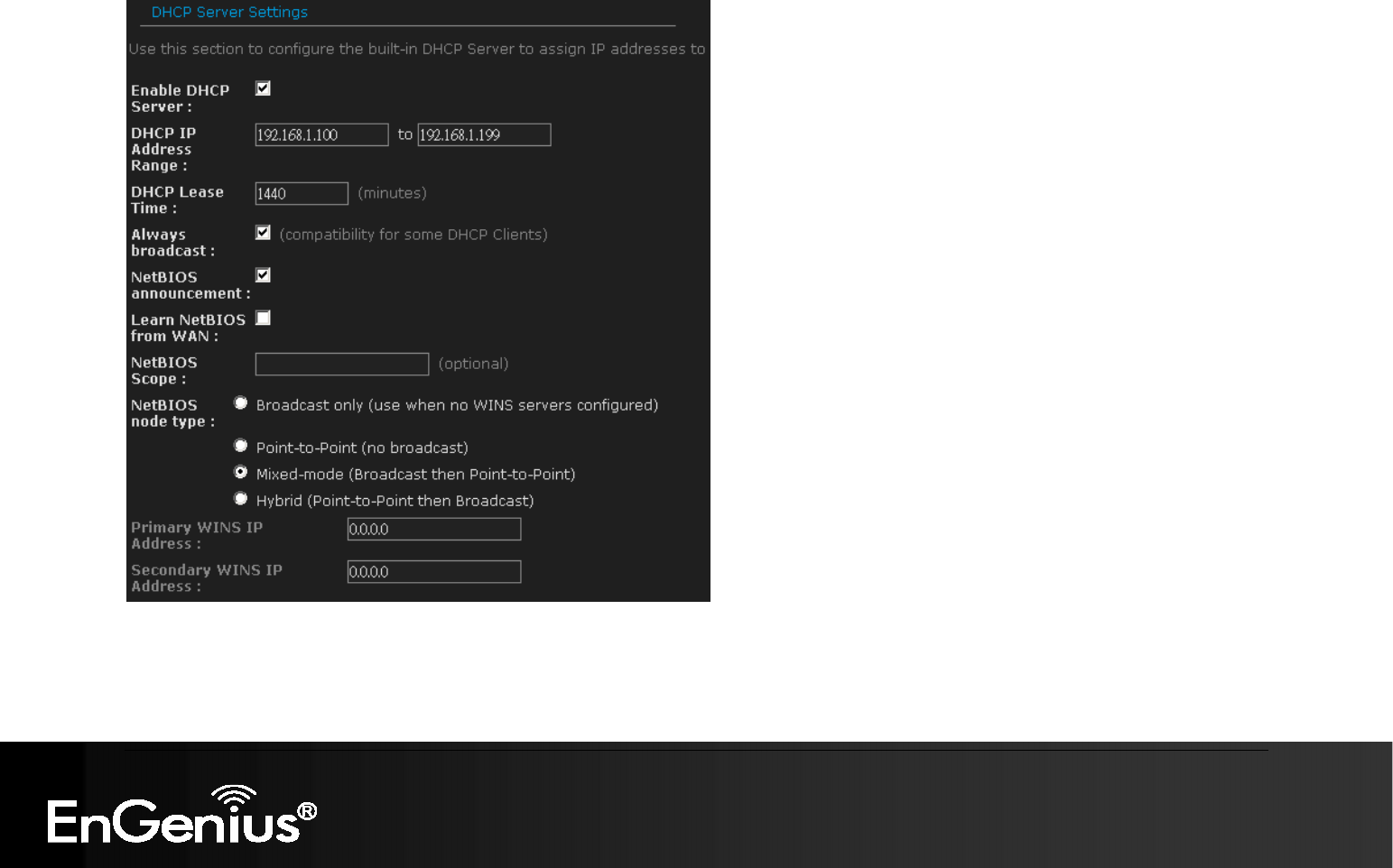
DHCP Server Settings
DHCP stands for Dynamic Host Configuration Protocol. The DHCP section is where you configure the built-in DHCP Server to
assign IP addresses to the computers and other devices on your local area network (LAN).

51
51
Enable DHCP Server: Once your router is properly configured and this option is enabled, the DHCP Server will manage the IP
addresses and other network configuration information for computers and other devices connected to your Local Area Network. There
is no need for you to do this yourself. The computers (and other devices) connected to your LAN also need to have their TCP/IP
configuration set to "DHCP" or "Obtain an IP address automatically". When you set Enable DHCP Server, the following options are
displayed.
DHCP IP Address Range: These two IP values (from and to) define a range of IP addresses that the DHCP Server uses when
assigning addresses to computers and devices on your Local Area Network. Any addresses that are outside of this range are not
managed by the DHCP Server; these could, therefore, be used for manually configured devices or devices that cannot use DHCP to
obtain network address details automatically.
It is possible for a computer or device that is manually configured to have an address that does reside within this range. In this case
the address should be reserved (see DHCP Reservation below), so that the DHCP Server knows that this specific address can only
be used by a specific computer or device.
Your router, by default, has a static IP address of 192.168.0.1. This means that addresses 192.168.0.2 to 192.168.0.254 can be
made available for allocation by the DHCP Server.
DHCP Lease Time: The amount of time that a computer may have an IP address before it is required to renew the lease. The lease
functions just as a lease on an apartment would. The initial lease designates the amount of time before the lease expires. If the tenant
wishes to retain the address when the lease is expired then a new lease is established. If the lease expires and the address is no
longer needed than another tenant may use the address.
Always Broadcast: If all the computers on the LAN successfully obtain their IP addresses from the router's DHCP server as expected,
this option can remain disabled. However, if one of the computers on the LAN fails to obtain an IP address from the router's DHCP
server, it may have an old DHCP client that incorrectly turns off the broadcast flag of DHCP packets. Enabling this option will cause
the router to always broadcast its responses to all clients, thereby working around the problem, at the cost of increased broadcast
traffic on the LAN.
NetBIOS Advertisement: Check this box to allow the DHCP Server to offer NetBIOS configuration settings to the LAN hosts.
NetBIOS allows LAN hosts to discover all other computers within the network, e.g. within Network Neighbourhood.
Learn NetBIOS information from WAN: If NetBIOS advertisement is swicthed on, switching this setting on causes WINS information
to be learned from the WAN side, if available. Turn this setting off to configure manually.

52
52
Primary WINS Server IP address: Configure the IP address of the preferred WINS server. WINS Servers store information regarding
network hosts, allowing hosts to 'register' themselves as well as discover other available hosts, e.g. for use in Network Neighbourhood.
This setting has no effect if the 'Learn NetBIOS information from WAN' is activated.
Secondary WINS Server IP address: Configure the IP address of the backup WINS server, if any. This setting has no effect if the
'Learn NetBIOS information from WAN' is activated.
NetBIOS Scope: This is an advanced setting and is normally left blank. This allows the configuration of a NetBIOS 'domain' name
under which network hosts operate. This setting has no effect if the 'Learn NetBIOS information from WAN' is activated.
NetBIOS Registration Mode: Indicates how network hosts are to perform NetBIOS name registration and discovery.
Broadcast only: Local network broadcast only. This setting is useful where there are no WINS servers available, however, it is
preferred you try Mixed Mode operation first. This setting has no effect if the 'Learn NetBIOS information from WAN' is activated.
Point-to-Point: Use WINS servers only. This setting is useful to force all NetBIOS operation to the configured WINS servers. You
must have configured at least the primary WINS server IP to point to a working WINS server.
Mixed Mode: First, the Broadcast operation is performed to register hosts and discover other hosts, if broadcast operation fails,
WINS servers are tried, if any. This mode favours broadcast operation which may be preferred if WINS servers are reachable by a
slow network link and the majority of network services such as servers and printers are local to the LAN.
Hybrid: First WINS servers are tried, if any, followed by local network broadcast. This is generally the preferred mode if you have
configured WINS servers.
53
53
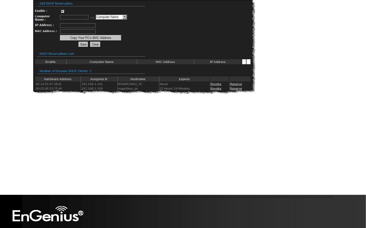
Add/Edit DHCP Reservation
This option lets you reserve IP addresses, and assign the same IP address to the network device with the specified MAC address any time
it requests an IP address. This is almost the same as when a device has a static IP address except that the device must still request an IP
address from the router. The router will provide the device the same IP address every time. DHCP Reservations are helpful for server
computers on the local network that are hosting applications such as Web and FTP. Servers on your network should either use a static IP
address or use this option.
Computer Name: You can assign a name for each computer that is given a reserved IP address. This may help you keep track of
which computers are assigned this way. Example: Game Server.
IP Address: The LAN address that you want to reserve.
MAC Address: To input the MAC address of your system, enter it in manually or connect to the router's Web-Management interface
from the system and click the Copy Your PC's MAC Address button. A MAC address is usually located on a sticker on the bottom of a
network device. The MAC address is comprised of twelve digits. Each pair of hexadecimal digits are usually separated by dashes or

54
54
colons such as 00-0D-88-11-22-33 or 00:0D:88:11:22:33. If your network device is a computer and the network card is already located
inside the computer, you can connect to the router from the computer and click the Copy Your PC's MAC Address button to enter the
MAC address.
DHCP Reservations List
This shows clients that you have specified to have reserved DHCP addresses. Click the Enable checkbox at the left to directly
activate or de-activate the entry. An entry can be changed by clicking the Edit icon or can be deleted by clicking the Delete icon.
When you click the Edit icon, the item is highlighted, and the "Edit DHCP Reservation" section is activated for editing.
Number of Dynamic DHCP Clients
In this section you can see what LAN devices are currently leasing IP addresses.
Revoke: The Revoke option is available for the situation in which the lease table becomes full or nearly full, you need to recover
space in the table for new entries, and you know that some of the currently allocated leases are no longer needed. Clicking Revoke
cancels the lease for a specific LAN device and frees an entry in the lease table. Do this only if the device no longer needs the
leased IP address, because, for example, it has been removed from the network.
Reserve: The Reserve option converts this dynamic IP allocation into a DHCP Reservation and adds the corresponding entry to the
DHCP Reservations List.

55
55
6.2.4. Wireless Settings
These options allow you to enable/disable the wireless interface, switch between the 11b, 11g, 11n and mixed radio band and channel
frequency
Enable Wireless: Place a check in this box to enable the wireless interface, it is enabled by default.
Wireless Network Name: The SSID is a unique named shared amongst all the points of the wireless network. The SSID must be
identical on all points of the wireless network and cannot exceed 32 characters.
802.11 Mode: Select the IEEE 802.11 mode from the drop-down list. For example, if you are certain that the wireless network will
be using only IEEE 802.11g clients, then it is recommended to select 802.11g only instead of 2.4 GHz B+G which will reduce the
performance of the wireless network. You may also select Mixed 802.11n, 802.11g and 802.11b. If all of the wireless devices
you want to connect with this router can connect in the same transmission mode, you can improve performance slightly by
choosing the appropriate "Only" mode. If you have some devices that use a different transmission mode, choose the appropriate
"Mixed" mode.

56
56
Wireless Channel: Select a channel from the drop-down list. The channels available are based on the country’s regulation. A
wireless network uses specific channels in the wireless spectrum to handle communication between clients. Some channels in
your area may have interference from other electronic devices. Choose the clearest channel to help optimize the performance
and coverage of your wireless network.
Transmission Rate: Select a transmission rate from the drop-down list. It is recommended to use the Best (automatic) option.
Channel Width: Select a channel width from the drop-down list.
Visibility Status: Select Visible or Invisible. This is the SSID broadcast feature.
When this option is set to Visible, your wireless network
name is broadcast to anyone within the range of your signal
. If you're not using encryption then they could connect to your network. When
Invisible mode is enabled, you must enter the Wireless Network Name (SSID) on the client manually to connect to the network.
Show Active Clients: Click on this button to view a list of clients that are associated with this device.
Click on the Save Changes button to store these settings.
57
57
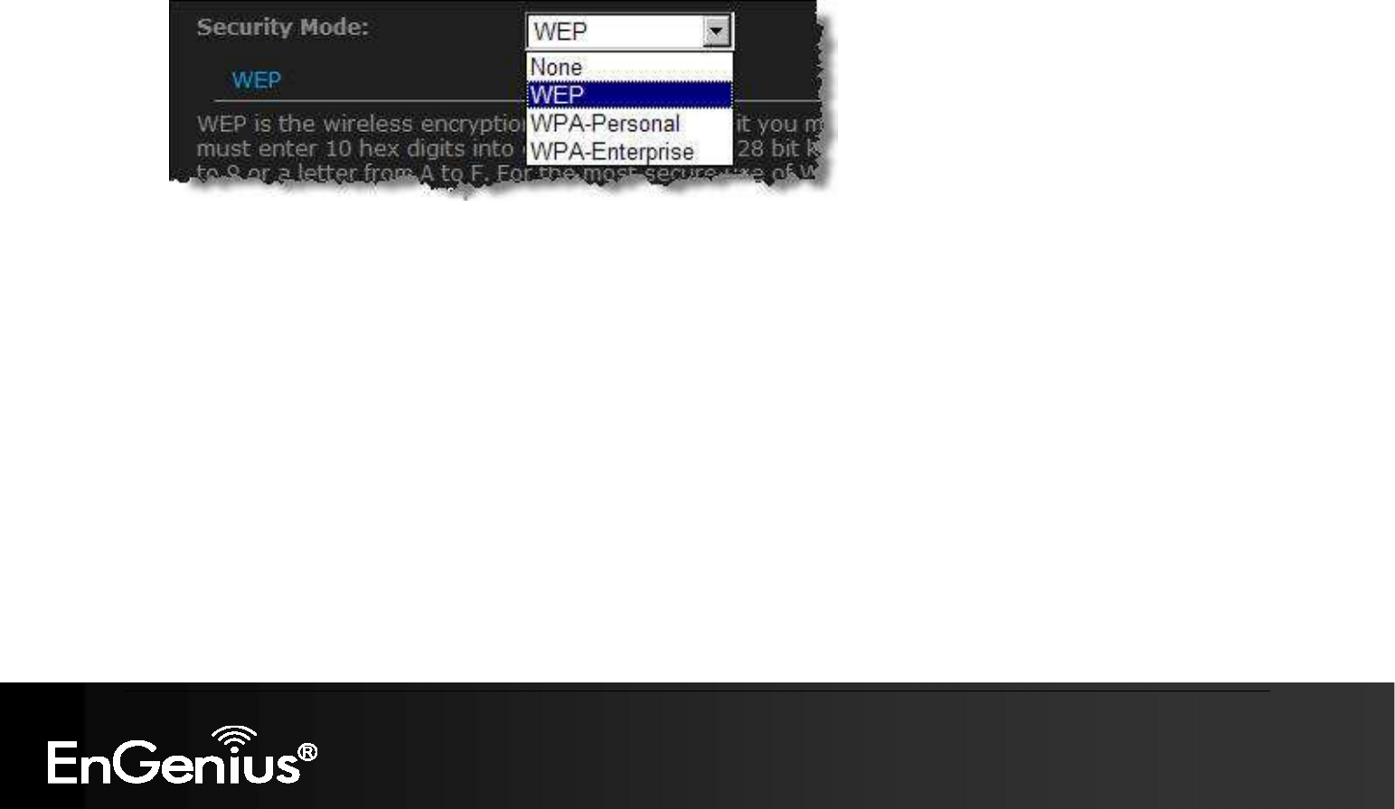
6.2.4.1. Wireless Security Mode
To protect your privacy this mode supports several types of wireless security: WEP WPA, WPA2, and WPA-Mixed. WEP is the original
wireless encryption standard. WPA provides a higher level of security. The following section describes the security configuration in detail.

58
58
6.2.4.2. WEP (Wired Equivalent Privacy)
Select the WEP from the drop-down list if your wireless network uses WEP encryption. WEP is an acronym for Wired Equivalent
Privacy, and is a security protocol that provides the same level of security for wireless networks as for a wired network.
WEP is not as secure as WPA encryption. To gain access to a WEP network, you must know the key. The key is a string of
characters that you create. When using WEP, you must determine the level of encryption. The type of encryption determines the key length.
128-bit encryption requires a longer key than 64-bit encryption. Keys are defined by entering in a string in HEX (hexadecimal - using
characters 0-9, A-F) or ASCII (American Standard Code for Information Interchange - alphanumeric characters) format. ASCII format is
provided so you can enter a string that is easier to remember. The ASCII string is converted to HEX for use over the network. Four keys
can be defined so that you can change keys easily. A default key is selected for use on the network.
WEP Key Length: Select a 64-bit or 128-bit WEP key length from the drop-down list.
WEP Key 1-4: You may enter four different WEP keys.
Default WEP Key: You may use up to four different keys for four different networks. Select the current key that will be used.
Authentication: Select Open, or Shared Key. Authentication method from the drop-down list. An open system allows any client to
authenticate as long as it conforms to any MAC address filter policies that may have been set. All authentication packets are
transmitted without encryption. Shared Key sends an unencrypted challenge text string to any device attempting to communicate with
the AP. The device requesting authentication encrypts the challenge text and sends it back to the access point. If the challenge text is
encrypted correctly, the access point allows the requesting device to authenticate. It is recommended to select Auto if you are not sure
which authentication type is used.
Click on the Save Changes button to store these settings.

59
59
6.2.4.3. WPA Personal (Wi-Fi Protected Access)
Select the WPA-Personal from the drop-down list if your wireless network uses WPA encryption. WPA (Wi-Fi Protected Access)
was designed to improve upon the security features of WEP (Wired Equivalent Privacy). The technology is designed to work with existing
Wi-Fi products that have been enabled with WEP. WPA provides improved data encryption through the Temporal Integrity Protocol (TKIP),
which scrambles the keys using a hashing algorithm and by adding an integrity checking feature which makes sure that keys haven’t been
tampered with.
WPA Mode: Select the Auto WPA / WPA2 from the drop-down list.
Cipher Type: Select TKIP and AES as the cipher suite. The encryption algorithm used to secure the data communication. TKIP. Use
TKIP only. TKIP (Temporal Key Integrity Protocol) provides per-packet key generation and is based on WEP. AES. Use AES only.
AES (Advanced Encryption Standard) is a very secure block based encryption. Note that, if the bridge uses the AES option, the bridge
can associate with the access point only if the access point is also set to use only AES. TKIP and AES. The bridge negotiates the
cipher type with the access point, and uses AES when available.
Group Key Update Interval: Specify the number of seconds before the group key used for broadcast and multicast data is changed.
Pre-Shared Key: The key is entered as a pass-phrase of up to 63 alphanumeric characters in ASCII (American Standard Code for
Information Interchange) format at both ends of the wireless connection. It cannot be shorter than eight characters, although for proper
security it needs to be of ample length and should not be a commonly known phrase. This phrase is used to generate session keys
that are unique for each wireless client.
Click on the Save Changes button to store these settings.

60
60
6.2.4.4. WPA Enterprise (Wi-Fi Protected Access & 802.1x)
Select the WPA-Enterprise from the drop-down list if your wireless network uses WPA encryption. WPA (Wi-Fi Protected Access) was
designed to improve upon the security features of WEP (Wired Equivalent Privacy). The technology is designed to work with existing Wi-Fi
products that have been enabled with WEP. WPA provides improved data encryption through the Temporal Integrity Protocol (TKIP), which
scrambles the keys using a hashing algorithm and by adding an integrity checking feature which makes sure that keys haven’t been
tampered with.
This option works with a RADIUS Server to authenticate wireless clients. Wireless clients should have established the necessary
credentials before attempting to authenticate to the Server through this Gateway. Furthermore, it may be necessary to configure the
RADIUS Server to allow this Gateway to authenticate users.

61
61
WPA Mode: Select the WPA / WPA2 from the drop-down list.
Cipher Type: Select TKIP or AES as the cipher suite. The encryption algorithm used to secure the data communication. TKIP. Use
TKIP only. TKIP (Temporal Key Integrity Protocol) provides per-packet key generation and is based on WEP. AES. Use AES only.
AES (Advanced Encryption Standard) is a very secure block based encryption. Note that, if the bridge uses the AES option, the bridge
can associate with the access point only if the access point is also set to use only AES. TKIP and AES. The bridge negotiates the
cipher type with the access point, and uses AES when available.
Group Key Update Interval: Specify the number of seconds before the group key used for broadcast and multicast data is changed.
Authentication Timeout: Specify the number of minutes after which the client will be required to re-authenticate.
RADIUS Server IP Address: Specify the IP address of the RADIUS server.
RADIUS Server Port: Specify the port number of the RADIUS server, the default port is 1812.
RADIUS Server Shared Secret: Specify the pass-phrase that is matched on the RADIUS Server.
MAC Address Authentication: Place a check in this box if you would like the user to always authenticate using the same computer.
Optional Backup RADIUS server: This option enables configuration of an optional second RADIUS server. A second RADIUS server
can be used as backup for the primary RADIUS server. The second RADIUS server is consulted only when the primary server is not
available or not responding.
Click on the Save Changes button to store these settings.

62
62
6.3. Advanced
Click on the Advanced link on the navigation tree menu.
The configuration steps for each option are described below.
63
63
6.3.1.
Advanced Wireless
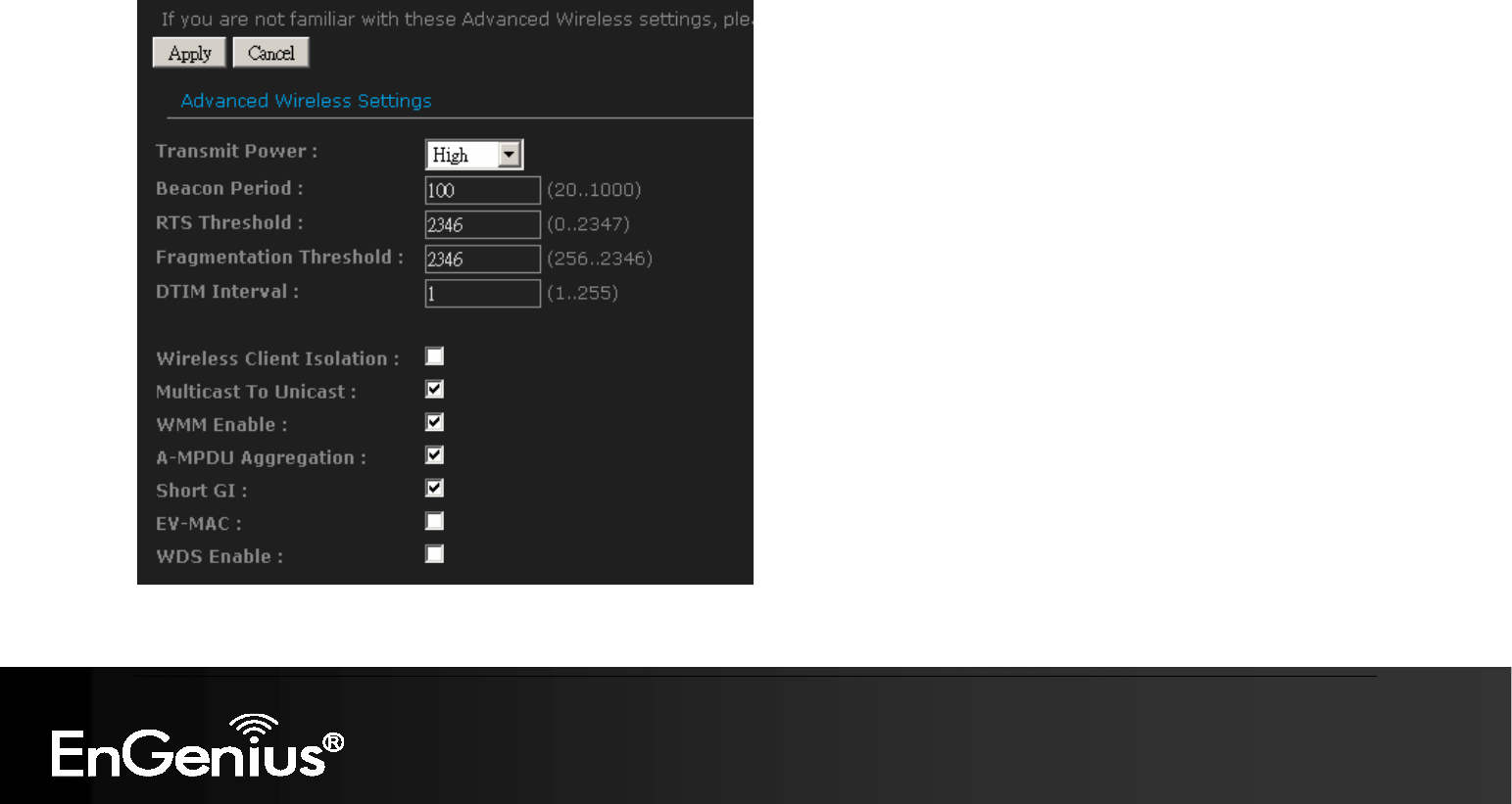
By clicking on Advanced tab, you will be able to access Advanced Wireless page.
If you are not familiar with Advanced Wireless Settings, please read the help section before attempting to modify these
settings.
Transmit Power: Set the power output of the wireless signal

64
64
Beacon Period:
Beacons are packets sent by a wireless router to synchronize wireless devices. Specify a Beacon
Period value between 20 and 1000. The default value is set to 100 milliseconds. Values that are not a multiple of 4,
are forced to a multiple of 4.
RTS Threshold:
When an excessive number of wireless packet collisions are occurring, wireless performance can be
improved by using the RTS/CTS (Request to Send/Clear to Send) handshake protocol. The wireless transmitter will
begin to send RTS frames (and wait for CTS) when data frame size in bytes is greater than the RTS Threshold. This
setting should remain at its default value of 2346 bytes.
Fragment Threshold:
Wireless frames can be divided into smaller units (fragments) to improve performance in the
presence of RF interference and at the limits of RF coverage. Fragmentation will occur when frame size in bytes is
greater than the Fragmentation Threshold. This setting should remain at its default value of 2346 bytes. Setting the
Fragmentation value too low may result in poor performance.
DTIM Interval: A Delivery Traffic Indication Message informs all wireless clients that the access point will be sending Multi-cast data.
Wireless Client Isolation:
Enabling Wireless Client Isolation (also known as L2 Isolation) prevents associated wireless
clients from communicating directly with each other by using low-level (link layer) protocols and without passing
through the router.
Muticast to Unicast:
When multiple wireless clients are receiving streaming media, enabling this option can provide
better performance in some cases by transforming each multicast packet into multiple unicast packets. (Broadcast
packets are still sent out as broadcast packets.) If you experience interoperability problems when the AP is sending
streaming media to some legacy wireless clients, try turning this option off.
WMM Enable:
Enabling WMM can help control latency and jitter when transmitting multimedia content over a wireless
connection.
A-MPDU Aggregation:
Aggregation of wireless packets based on MAC protocol data units is a technique for
maximizing performance. This option should normally remain enabled.
Short GI:
Using a short (400ns) guard interval can increase throughput. However, it can also increase error rate in
some installations, due to increased sensitivity to radio-frequency reflections. Select the option that works best for
your installation.
EV-MAC:
Enable EV-MAC option for superior experience of wireless video streaming.
WDS Enable:
Specifies one-half of the WDS link. The other AP must also have the MAC address of this AP to create
the WDS link back to this AP. Enter a MAC address for each of the other APs that you want to connect with WDS.
65
65
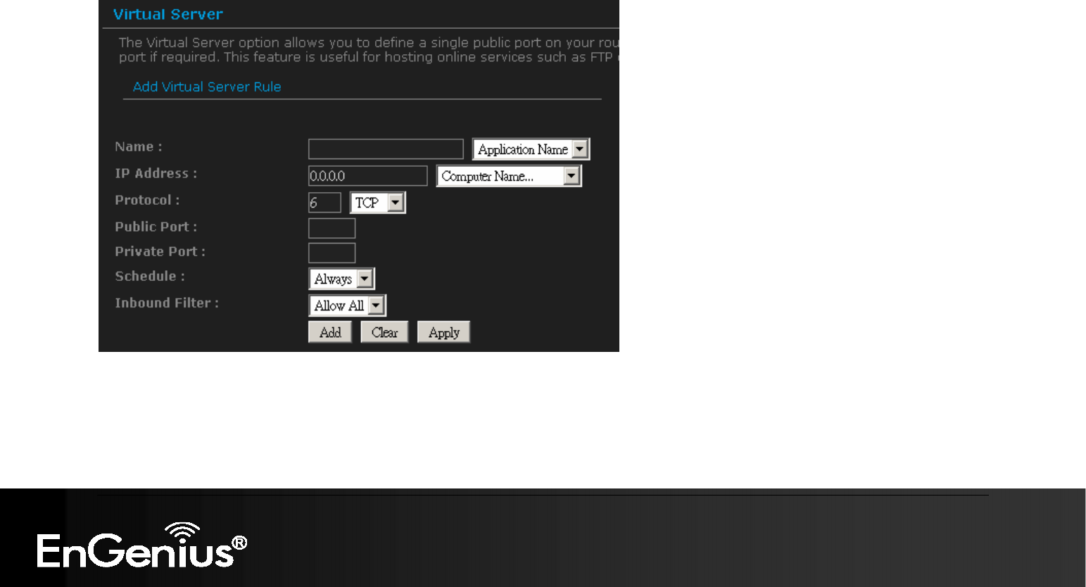
6.3.2. Virtual Server
The Virtual Server option gives Internet users access to services on your LAN. This feature is useful for hosting online services such as
FTP, Web, or game servers. For each Virtual Server, you define a public port on your router for redirection to an internal LAN IP Address
and LAN port.
Name: Assign a meaningful name to the virtual server, for example Web Server. Several well-known types of virtual server are
available from the Application Name drop-down list. Selecting one of these entries fills some of the remaining parameters with
standard values for that type of server.
IP Address: Specify the IP address for the virtual server entry.
Protocol: Specify a protocol or select one from the drop-down list.