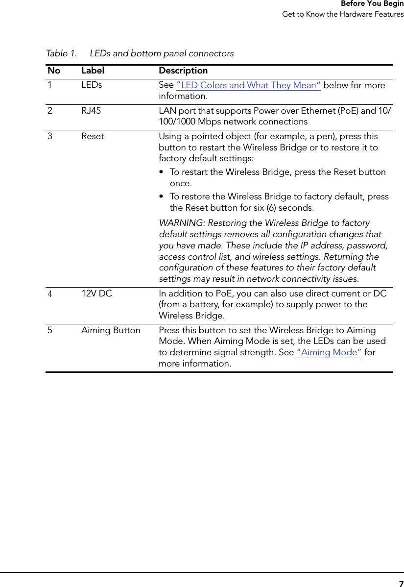
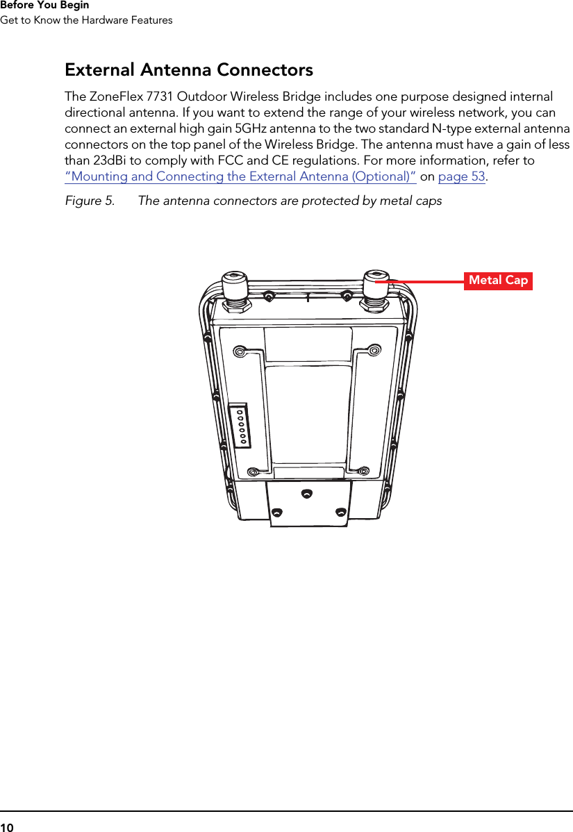
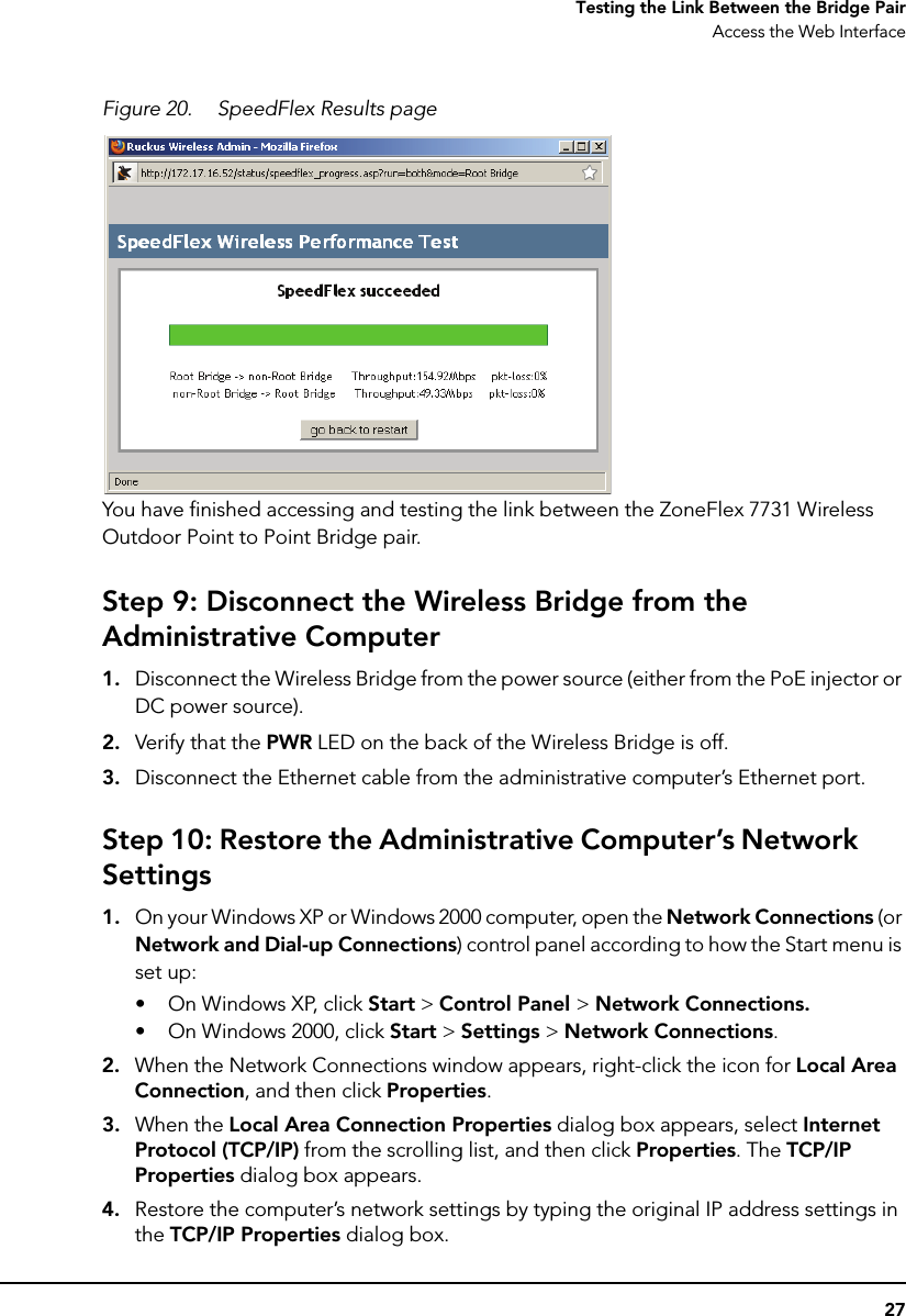
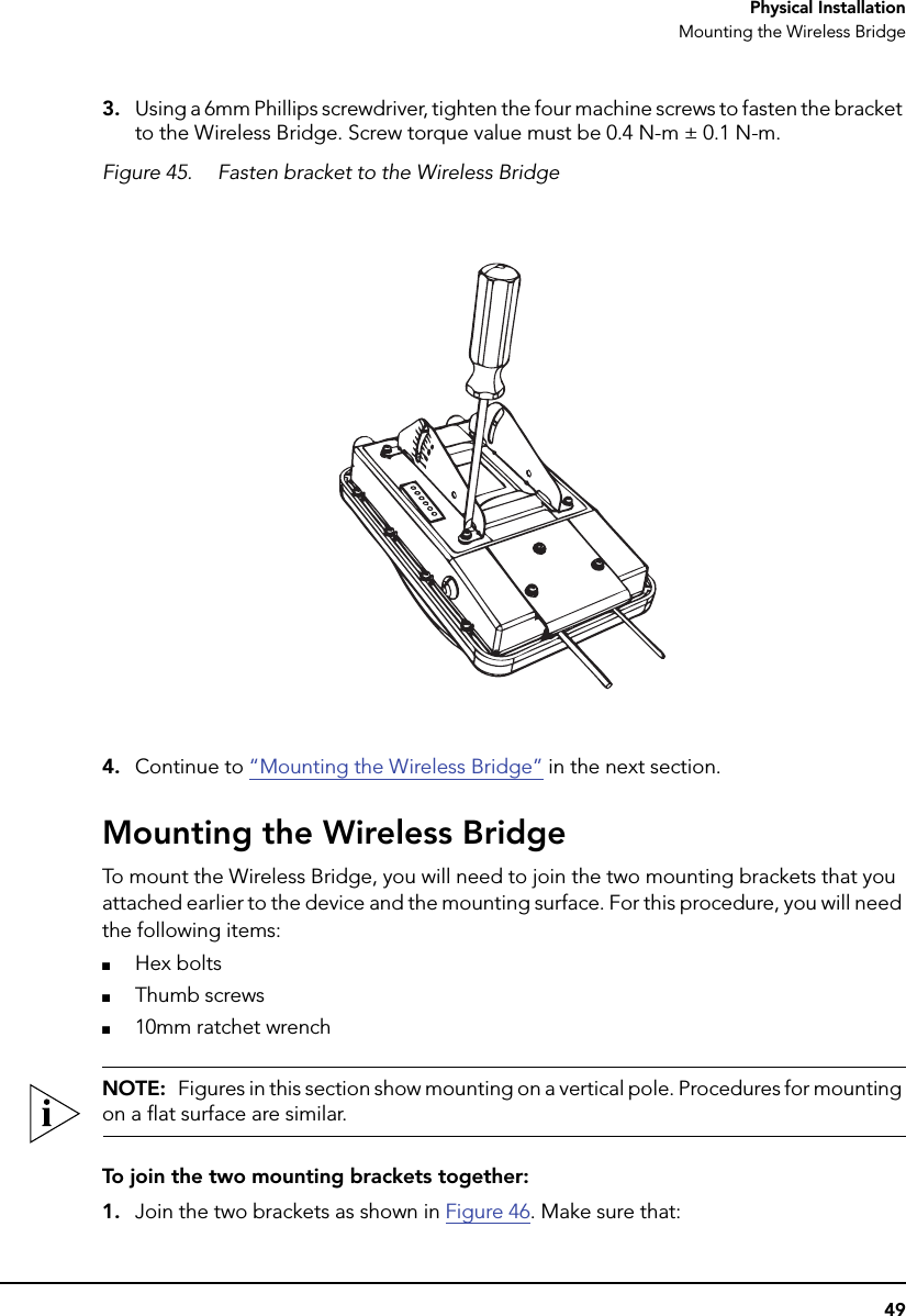
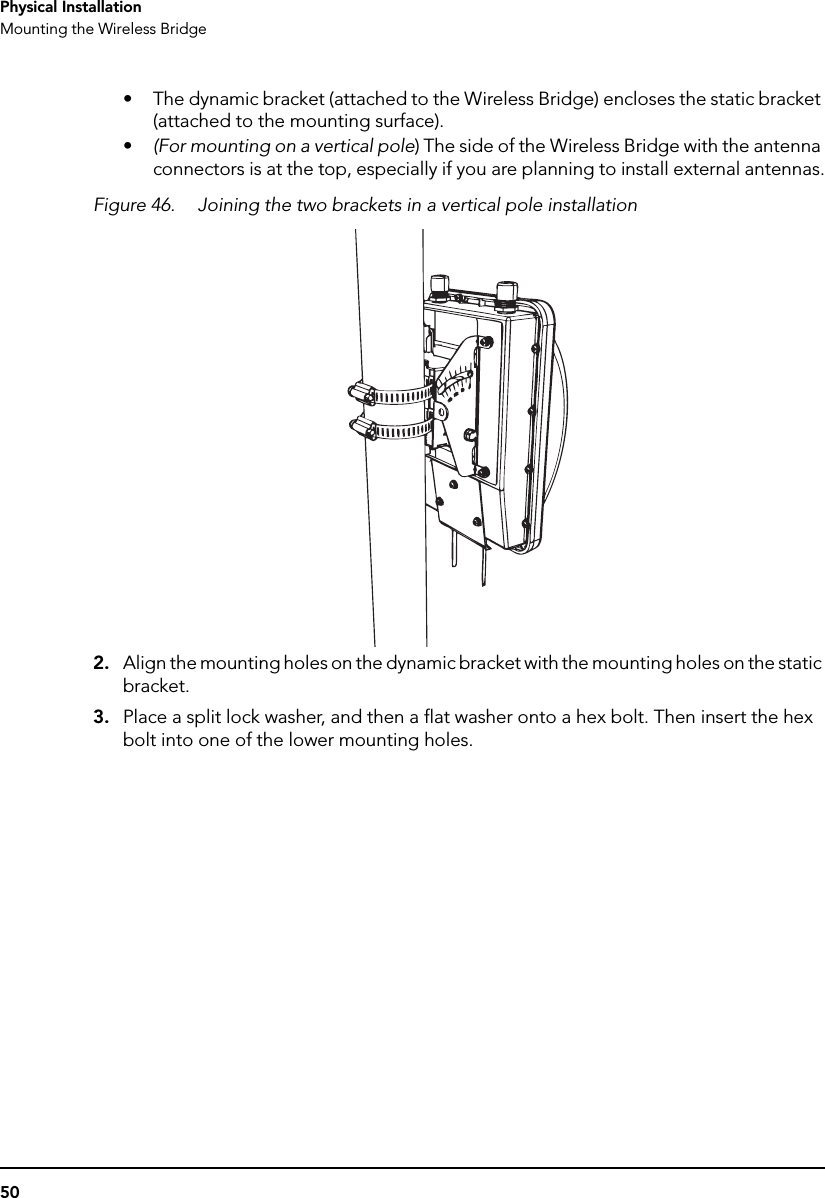
Senao Networks ZF7731 Zone Flex 7731 802.11n Outdoor Point to Point Bridge User Manual Bali GSG
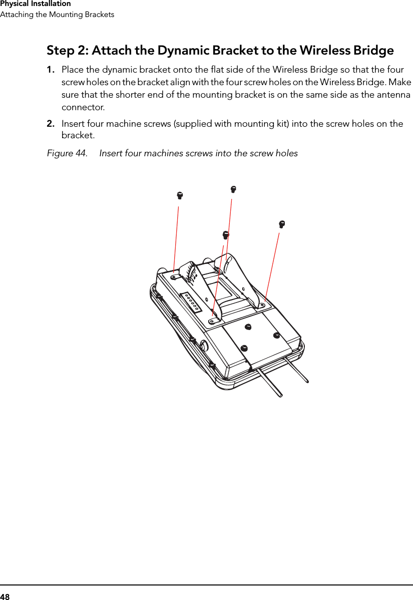
Senao Networks, Inc. Zone Flex 7731 802.11n Outdoor Point to Point Bridge Bali GSG
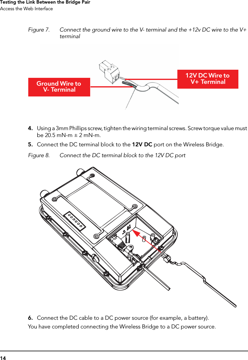
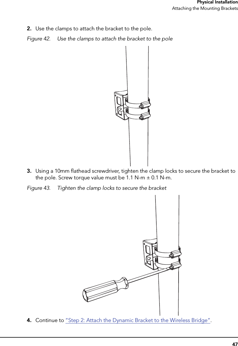
Contents
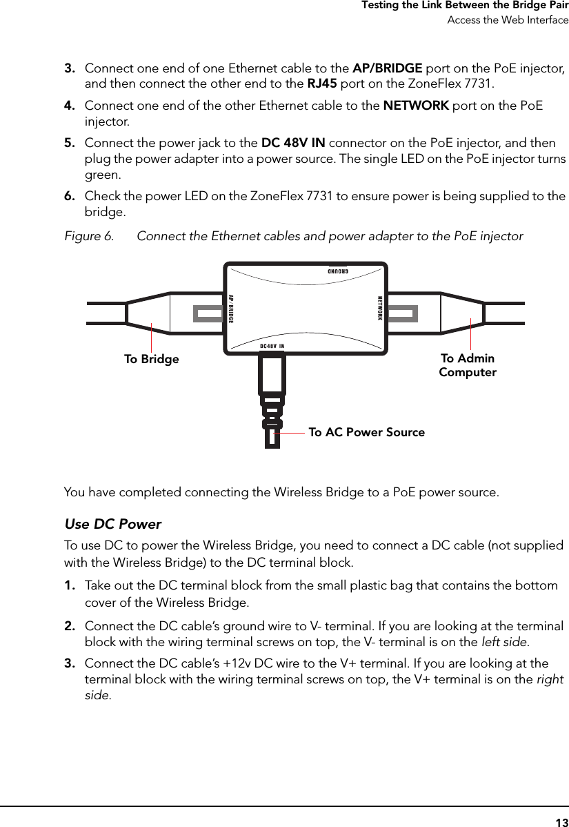
- 1. User Manual
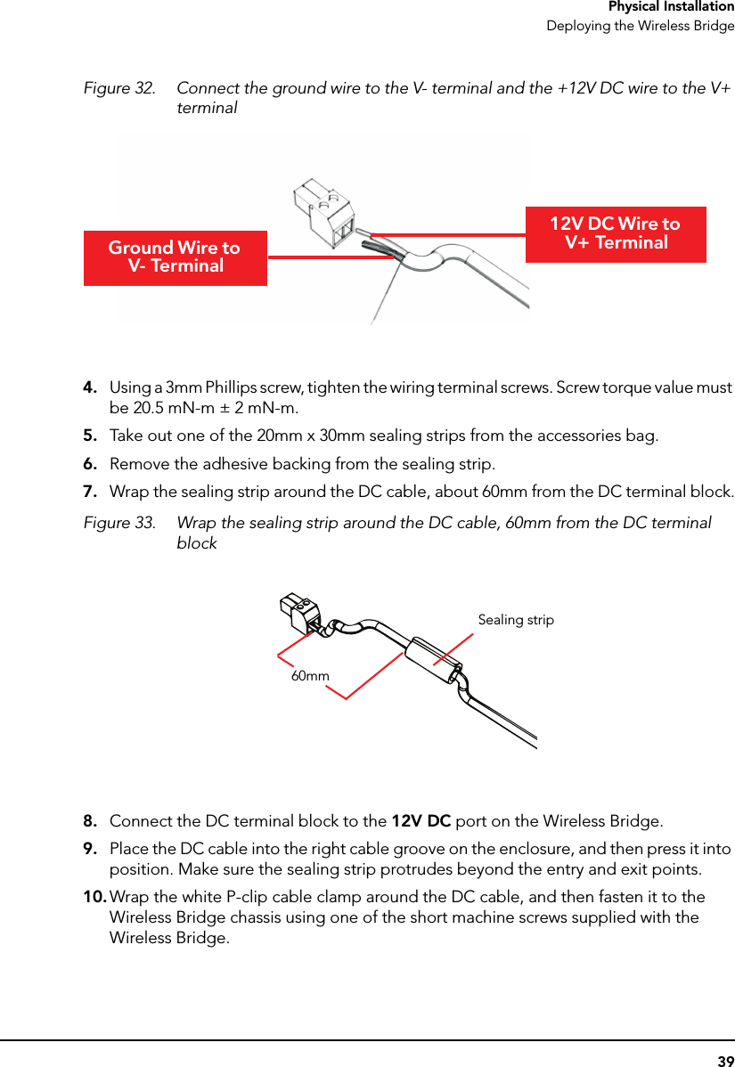
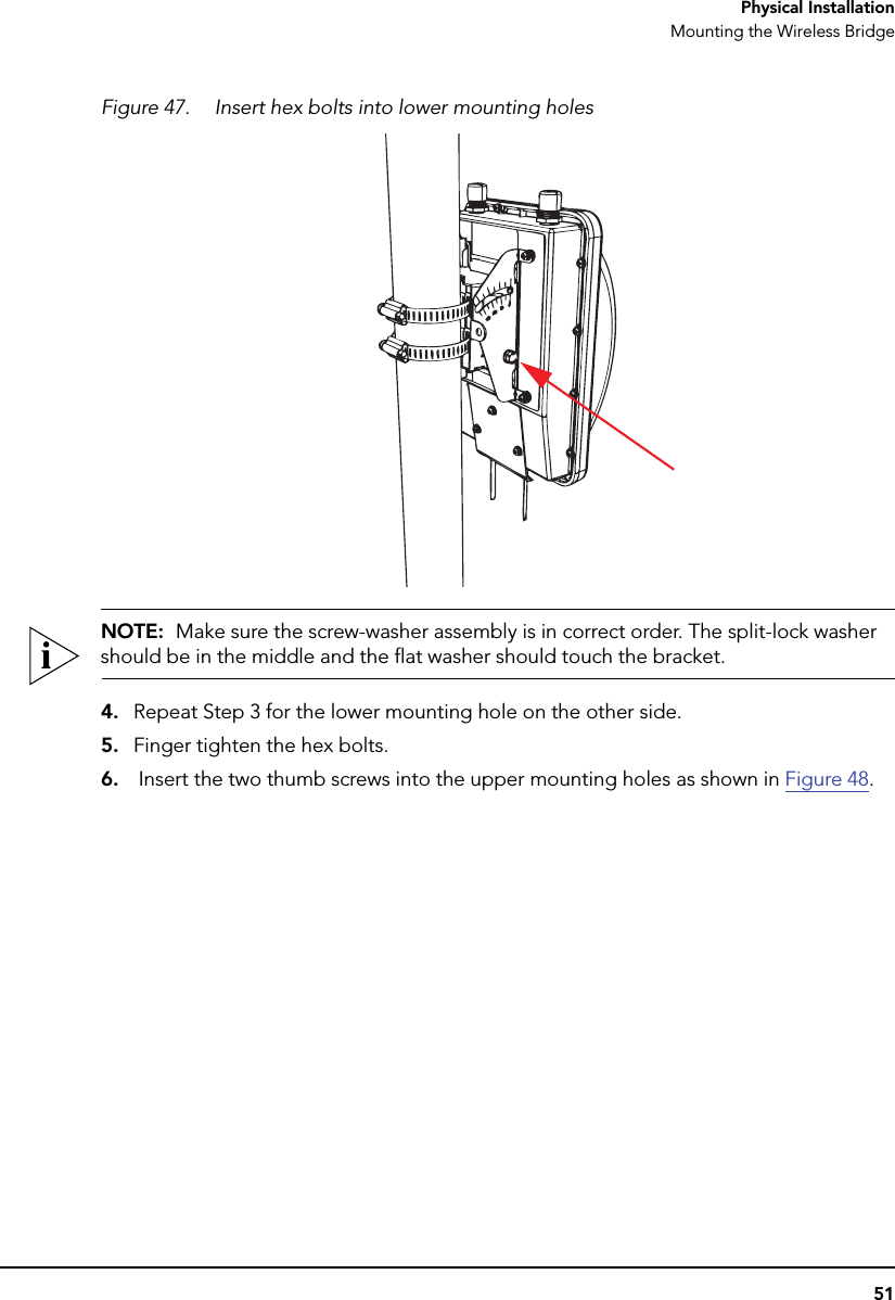
- 2. User manual
- 3. manual
- 4. MANUAL 1
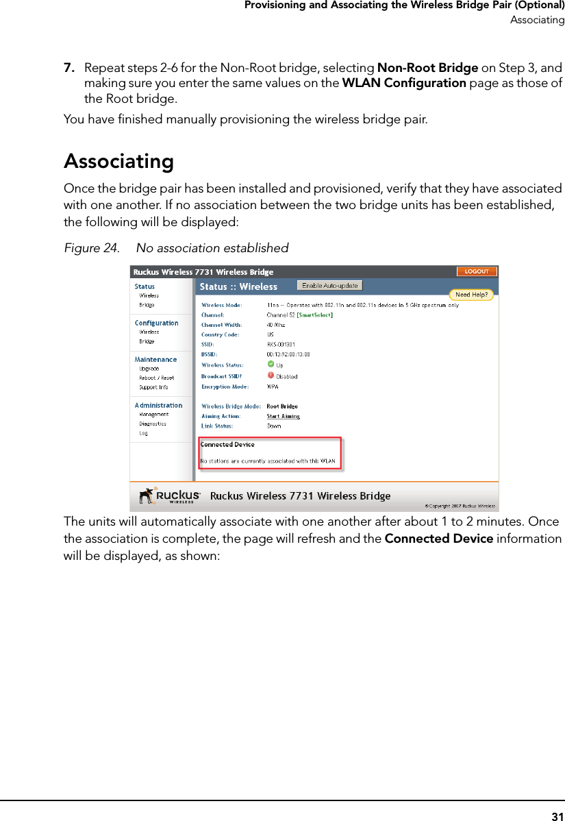
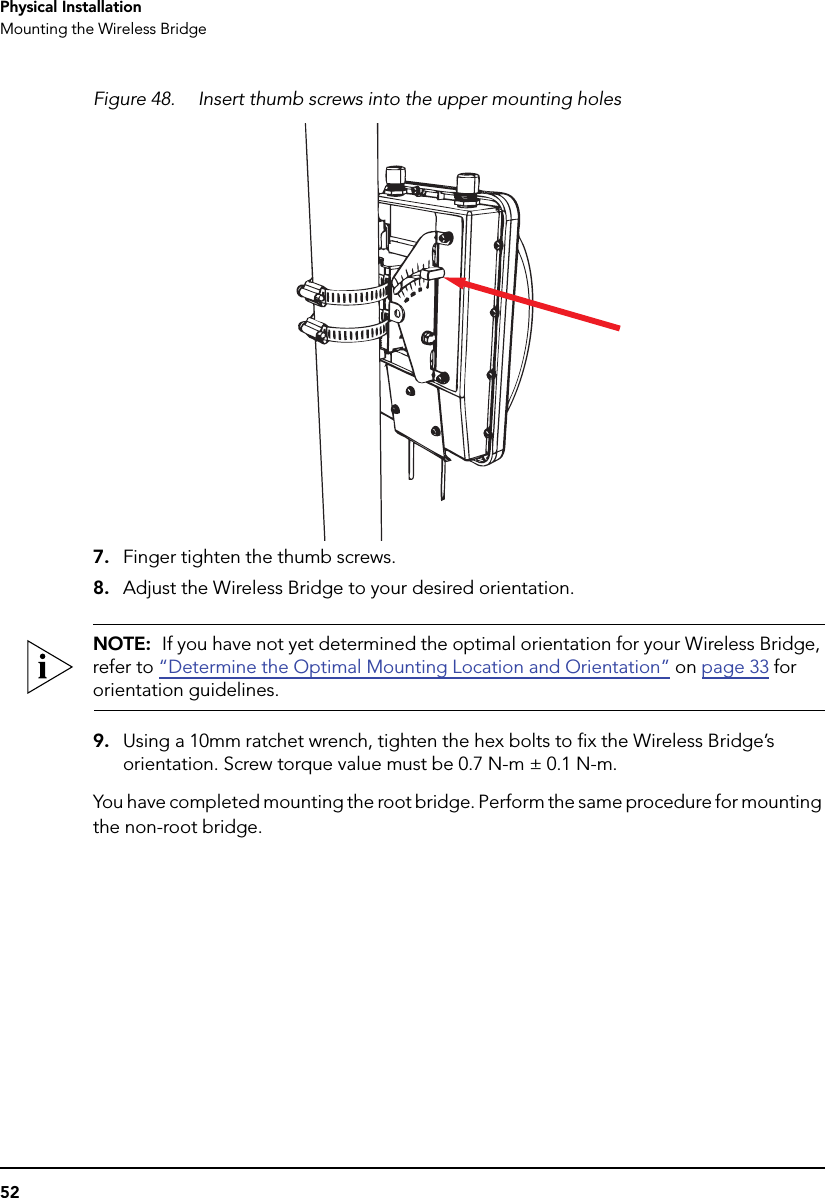
- 5. MANUAL 2
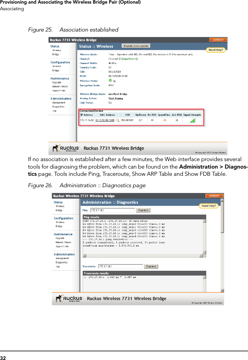
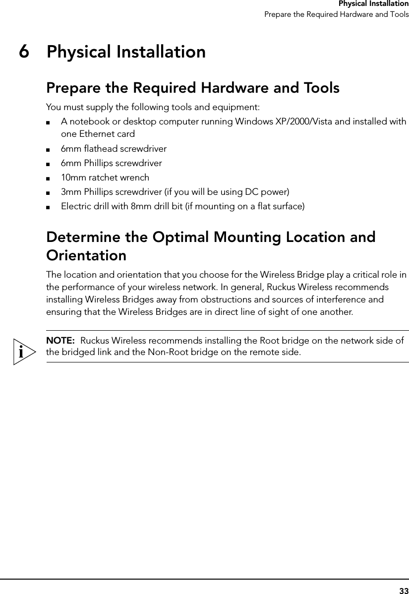
User Manual
![Česky [Czech] Ruckus Wireless tímto prohlašuje, že tento Radio LAN je ve shodě se základními požadavky a dalšími příslušnými ustanoveními směrnice 1999/5/ES. Dansk [Danish] Undertegnede Ruckus Wireless erklærer herved, at følgende udstyr Radio LAN overholder de væsentlige krav og øvrige relevante krav i direktiv 1999/5/EF. Deutsch [German] Hiermit erklärt Ruckus Wireless, dass sich das Gerät Radio LAN in Übereinstimmung mit den grundlegenden Anforderungen und den übrigen einschlägigen Bestimmungen der Richtlinie 1999/5/EG befindet. Eesti [Estonian] Käesolevaga kinnitab Ruckus Wireless seadme Radio LAN vastavust direktiivi 1999/5/EÜ põhinõuetele ja nimetatud direktiivist tulenevatele teistele asjakohastele sätetele. English Hereby, Ruckus Wireless declares that this Radio LAN is in compliance with the essential requirements and other relevant provisions of Directive 1999/5/EC. Español [Spanish] Por medio de la presente Ruckus Wireless declara que el Radio LAN cumple con los requisitos esenciales y cualesquiera otras disposiciones aplicables o exigibles de la Directiva 1999/5/CE. Ελληνική [Greek] ΜΕ ΤΗΝ ΠΑΡΟΥΣΑ Ruckus Wireless ΔΗΛΩΝΕΙ ΟΤΙ Radio LAN ΣΥΜΜΟΡΦΩΝΕΤΑΙ ΠΡΟΣ ΤΙΣ ΟΥΣΙΩΔΕΙΣ ΑΠΑΙΤΗΣΕΙΣ ΚΑΙ ΤΙΣ ΛΟΙΠΕΣ ΣΧΕΤΙΚΕΣ ΔΙΑΤΑΞΕΙΣ ΤΗΣ ΟΔΗΓΙΑΣ 1999/5/ΕΚ. Français [French] Par la présente Ruckus Wireless déclare que l'appareil Radio LAN est conforme aux exigences essentielles et aux autres dispositions pertinentes de la directive 1999/5/CE. Italiano [Italian] Con la presente Ruckus Wireless dichiara che questo Radio LAN è conforme ai requisiti essenziali ed alle altre disposizioni pertinenti stabilite dalla direttiva 1999/5/CE. Latviski [Latvian] Ar šo Ruckus Wireless deklarē, ka Radio LAN atbilst Direktīvas 1999/5/EK būtiskajām prasībām un citiem ar to saistītajiem noteikumiem. Lietuvių [Lithuanian] Šiuo Ruckus Wireless deklaruoja, kad šis Radio LAN atitinka esminius reikalavimus ir kitas 1999/5/EB Direktyvos nuostatas. Nederlands [Dutch] Hierbij verklaart Ruckus Wireless dat het toestel Radio LAN in overeenstemming is met de essentiële eisen en de andere relevante bepalingen van richtlijn 1999/5/EG. Malti [Maltese] Hawnhekk, Ruckus Wireless, jiddikjara li dan Radio LAN jikkonforma mal-ħtiġijiet essenzjali u ma provvedimenti oħrajn relevanti li hemm fid-Dirrettiva 1999/5/EC. Magyar [Hungarian] Alulírott, Ruckus Wireless nyilatkozom, hogy a Radio LAN megfelel a vonatkozó alapvetõ követelményeknek és az 1999/5/EC irányelv egyéb elõírásainak. Polski [Polish] Niniejszym Ruckus Wireless oświadcza, że Radio LAN jest zgodny z zasadniczymi wymogami oraz pozostałymi stosownymi postanowieniami Dyrektywy 1999/5/EC. Português [Portuguese] Ruckus Wireless declara que este Radio LAN está conforme com os requisitos essenciais e outras disposições da Directiva 1999/5/CE. Slovensko [Slovenian] Ruckus Wireless izjavlja, da je ta Radio LAN v skladu z bistvenimi zahtevami in ostalimi relevantnimi določili direktive 1999/5/ES. Slovensky [Slovak] Ruckus Wireless týmto vyhlasuje, že Radio LAN spĺňa základné požiadavky a všetky príslušné ustanovenia Smernice 1999/5/ES. Suomi [Finnish] Ruckus Wireless vakuuttaa täten että Radio LAN tyyppinen laite on direktiivin 1999/5/EY oleellisten vaatimusten ja sitä koskevien direktiivin muiden ehtojen mukainen. Svenska [Swedish] Härmed intygar Ruckus Wireless att denna Radio LAN står I överensstämmelse med de väsentliga egenskapskrav och övriga relevanta bestämmelser som framgår av direktiv 1999/5/EG. Íslenska [Icelandic] Hér með lýsir Ruckus Wireless yfir því að Radio LAN er í samræmi við grunnkröfur og aðrar kröfur, sem gerðar eru í tilskipun 1999/5/EC. Norsk [Norwegian] Ruckus Wireless erklærer herved at utstyret Radio LAN er i samsvar med de grunnleggende krav og øvrige relevante krav i direktiv 1999/5/EF. 800-70238-001-A](https://usermanual.wiki/Senao-Networks/ZF7731.User-Manual/User-Guide-1182635-Page-3.png)