Senao Networks ZF7731 Zone Flex 7731 802.11n Industrial Point to Point Bridge User Manual Bali GSG
Senao Networks, Inc. Zone Flex 7731 802.11n Industrial Point to Point Bridge Bali GSG
UserManual.wiki
>
Senao Networks
>
ZF7731 User Manual
>
MANUAL 1
Contents
1.
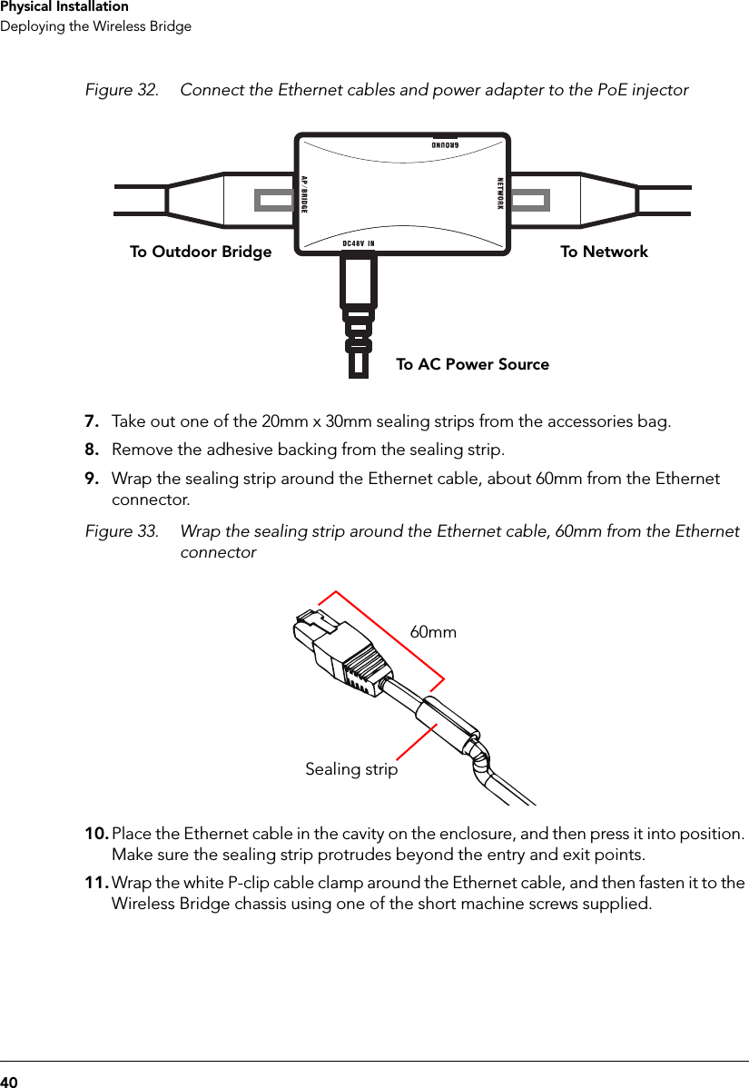
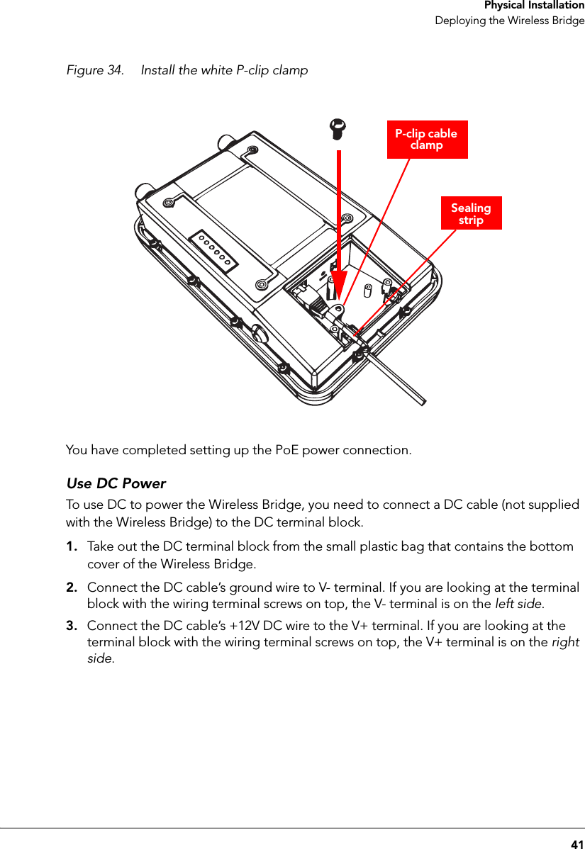
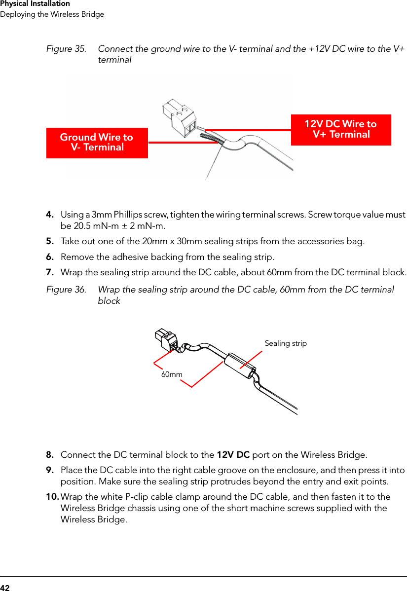
User Manual
2.
User manual
3.
manual
4.
MANUAL 1
5.
MANUAL 2
MANUAL 1
Navigation menu
Upload a User Manual
Namespaces
Wiki Guide
HTML
PDF
Info
Views
User Manual
Discussion / Help
Navigation