Senao Networks ZF7731 Zone Flex 7731 802.11n Industrial Point to Point Bridge User Manual Bali GSG
Senao Networks, Inc. Zone Flex 7731 802.11n Industrial Point to Point Bridge Bali GSG
Contents
MANUAL 1

Ruckus Wireless®
ZoneFlex® 7731 802.11n
Point to Point Wireless Bridge
Getting Started Guide
Part Number 800-70236-001 (Revision E)
Published December 2009
www.ruckuswireless.com

i
1About This Getting Started Guide . . . . . . . . . . . . . . . . . . . . . . . . . . . . . . . . . . . . . . . . . . . . 1
Related Documentation . . . . . . . . . . . . . . . . . . . . . . . . . . . . . . . . . . . . . . . . . . . . . . . . . . . 1
2Unpacking the ZoneFlex Wireless Bridge. . . . . . . . . . . . . . . . . . . . . . . . . . . . . . . . . . . . . . . 2
Package Contents . . . . . . . . . . . . . . . . . . . . . . . . . . . . . . . . . . . . . . . . . . . . . . . . . . . . . . . . 2
Mounting Kit Contents . . . . . . . . . . . . . . . . . . . . . . . . . . . . . . . . . . . . . . . . . . . . . . . . . . . 4
Bottom Cover and Accessories . . . . . . . . . . . . . . . . . . . . . . . . . . . . . . . . . . . . . . . . . . . . 5
3Before You Begin . . . . . . . . . . . . . . . . . . . . . . . . . . . . . . . . . . . . . . . . . . . . . . . . . . . . . . . . . . 6
Prepare the Required Hardware and Tools . . . . . . . . . . . . . . . . . . . . . . . . . . . . . . . . . . . 6
Get to Know the Hardware Features . . . . . . . . . . . . . . . . . . . . . . . . . . . . . . . . . . . . . . . . . 6
LED Colors and What They Mean . . . . . . . . . . . . . . . . . . . . . . . . . . . . . . . . . . . . . . . . . . 9
Push Buttons . . . . . . . . . . . . . . . . . . . . . . . . . . . . . . . . . . . . . . . . . . . . . . . . . . . . . . . . . . 10
External Antenna Connectors . . . . . . . . . . . . . . . . . . . . . . . . . . . . . . . . . . . . . . . . . . . . 11
4Pre-Installation Configuration . . . . . . . . . . . . . . . . . . . . . . . . . . . . . . . . . . . . . . . . . . . . . . . 12
Summary of Pre-Installation Tasks . . . . . . . . . . . . . . . . . . . . . . . . . . . . . . . . . . . . . . . . . . 12
What You Will Need . . . . . . . . . . . . . . . . . . . . . . . . . . . . . . . . . . . . . . . . . . . . . . . . . . . . . 13
Access the Web Interface . . . . . . . . . . . . . . . . . . . . . . . . . . . . . . . . . . . . . . . . . . . . . . . . . 13
Step 1: Connect the Power and Ethernet Cables . . . . . . . . . . . . . . . . . . . . . . . . . . . . 13
Step 2: Prepare the Administrative Computer . . . . . . . . . . . . . . . . . . . . . . . . . . . . . . . 16
Step 3: Connect the Wireless Bridge to the Admin Computer . . . . . . . . . . . . . . . . . 18
Step 4: Log In to the Web Interface . . . . . . . . . . . . . . . . . . . . . . . . . . . . . . . . . . . . . . . 18
Step 5: Change the Country Code . . . . . . . . . . . . . . . . . . . . . . . . . . . . . . . . . . . . . . . . 20
Step 6: Change Optional Configuration Settings . . . . . . . . . . . . . . . . . . . . . . . . . . . . 22
Step 7: Change Non-Root Bridge Configuration Settings . . . . . . . . . . . . . . . . . . . . . 28
Step 8: Test the Link Between the Bridges . . . . . . . . . . . . . . . . . . . . . . . . . . . . . . . . . . 28
Step 9: Disconnect the Wireless Bridge from the Administrative Computer . . . . . . 30
Step 10: Restore the Administrative Computer’s Network Settings . . . . . . . . . . . . . 30
5Provisioning and Associating the Wireless Bridge Pair (Optional) . . . . . . . . . . . . . . . . . . 31
Auto Provisioning . . . . . . . . . . . . . . . . . . . . . . . . . . . . . . . . . . . . . . . . . . . . . . . . . . . . . . . 31
Manual Provisioning Using the Web Interface . . . . . . . . . . . . . . . . . . . . . . . . . . . . . . . . 32
Contents

ii
Associating . . . . . . . . . . . . . . . . . . . . . . . . . . . . . . . . . . . . . . . . . . . . . . . . . . . . . . . . . . . . 34
6Physical Installation. . . . . . . . . . . . . . . . . . . . . . . . . . . . . . . . . . . . . . . . . . . . . . . . . . . . . . . . 36
Prepare the Required Hardware and Tools . . . . . . . . . . . . . . . . . . . . . . . . . . . . . . . . . . 36
Determine the Optimal Mounting Location and Orientation . . . . . . . . . . . . . . . . . . . . 36
Become Familiar with the Installation Components . . . . . . . . . . . . . . . . . . . . . . . . . . . 37
Decide How You Will Supply Power to the Wireless Bridge . . . . . . . . . . . . . . . . . . . . . 39
Deploying the Wireless Bridge . . . . . . . . . . . . . . . . . . . . . . . . . . . . . . . . . . . . . . . . . . . . 39
Step 1: Complete the Power Connections . . . . . . . . . . . . . . . . . . . . . . . . . . . . . . . . . . 39
Step 2: Install the Back Panel Cover . . . . . . . . . . . . . . . . . . . . . . . . . . . . . . . . . . . . . . . 44
Step 3: Connect the Wireless Bridge to the Network . . . . . . . . . . . . . . . . . . . . . . . . . 44
Attaching the Mounting Brackets . . . . . . . . . . . . . . . . . . . . . . . . . . . . . . . . . . . . . . . . . . 46
What You Will Need . . . . . . . . . . . . . . . . . . . . . . . . . . . . . . . . . . . . . . . . . . . . . . . . . . . . 46
Step 1: Attach the Static Bracket to the Mounting Surface . . . . . . . . . . . . . . . . . . . . 46
Step 2: Attach the Dynamic Bracket to the Wireless Bridge . . . . . . . . . . . . . . . . . . . 51
Mounting the Wireless Bridge . . . . . . . . . . . . . . . . . . . . . . . . . . . . . . . . . . . . . . . . . . . . . 52
Mounting and Connecting the External Antenna (Optional) . . . . . . . . . . . . . . . . . . . . 56
7Aiming the Bridge Pair . . . . . . . . . . . . . . . . . . . . . . . . . . . . . . . . . . . . . . . . . . . . . . . . . . . . . 57
8Verifying the Connection . . . . . . . . . . . . . . . . . . . . . . . . . . . . . . . . . . . . . . . . . . . . . . . . . . . 59
9What to Do Next. . . . . . . . . . . . . . . . . . . . . . . . . . . . . . . . . . . . . . . . . . . . . . . . . . . . . . . . . . 60
Change the Administrative Password . . . . . . . . . . . . . . . . . . . . . . . . . . . . . . . . . . . . . . . 60
Using FlexMaster to Manage the Wireless Bridge . . . . . . . . . . . . . . . . . . . . . . . . . . . . 60
Read Related Documentation . . . . . . . . . . . . . . . . . . . . . . . . . . . . . . . . . . . . . . . . . . . . . 62

1
1About This Getting Started Guide
This Getting Started Guide provides information on how to set up the Ruckus Wireless
ZoneFlex 7731 802.11n Point to Point Wireless Bridge on your network. Topics covered in
this guide include installation, basic configuration, and device mounting.
This guide is intended for use by those responsible for installing and setting up network
equipment. Consequently, it assumes a basic working knowledge of local area networking,
wireless networking, and wireless devices.
Related Documentation
In addition to this guide, each Ruckus Wireless ZoneFlex 7731 802.11n Point to Point
Wireless Bridge documentation set includes the following:
■User Guide: Provides detailed information on how to configure the Wireless Bridge.
The User Guide is available for download on the Ruckus Wireless Support Web site at:
http://support.ruckuswireless.com/documents
■Release Notes: Provides late-breaking information about the current software release,
including new features, enhancements, and known issues. If the information in the
Release Notes differs from the information in this guide, follow the instructions in the
Release Notes.
■Online Help: Accessible from the ZoneFlex 7731 Web interface, the Online Help
provides information that helps you configure the device from the Web interface.

2
Unpacking the ZoneFlex Wireless Bridge
Package Contents
2Unpacking the ZoneFlex Wireless Bridge
1. Open the Wireless Bridge package, and then carefully remove the contents.
2. Return all packing materials to the shipping box, and put the box away in a dry location.
3. Verify that all items listed in Package Contents below are included in the package.
Check each item for damage. If any item is damaged or missing, notify your authorized
Ruckus Wireless sales representative.
Package Contents
The standard ZoneFlex 7731 Wireless Bridge package contains two ZoneFlex 7731 units
and two sets of accessories (one for each unit). A single unit package contains one
ZoneFlex 7731 unit and one set of accessories. Refer to Tabl e 1 for package contents for
either the single unit package or dual unit package.
Table 1. Package contents
Single Unit Two Units
• One ZoneFlex 7731 Point to Point
Wireless Bridge
• One PoE injector box (excluded in some
SKUs)
• One Power adapter box (SW DC48V/
0.42A AC100-240V) for the PoE injector
(excluded in some SKUs)
• One mounting kit (see “Mounting Kit
Contents” for details)
• One bag containing bottom Wireless
Bridge cover and related accessories
(see “Bottom Cover and Accessories”
for details)
• Service Level Agreement / Limited
Warranty Statement
• Regulatory Statement
• This Getting Started Guide
• Two ZoneFlex 7731 Point to Point
Wireless Bridge units, pre-provisioned as
a “Root Bridge” and a “Non-Root
Bridge”
• Two PoE injector boxes (excluded in
some SKUs)
• Two power adapter boxes (SW DC48V/
0.42A AC100-240V) for the PoE injector
(excluded in some SKUs)
• Two mounting kits (see “Mounting Kit
Contents” for details)
• Two bags containing bottom Wireless
Bridge cover and related accessories
(see “Bottom Cover and Accessories” for
details)
• Service Level Agreement / Limited
Warranty Statement
• Regulatory Statement
• This Getting Started Guide

3
Unpacking the ZoneFlex Wireless Bridge
Package Contents
WARNING: The Ruckus Wireless PoE injector and power adapter (if supplied with your
Wireless Bridge) are for indoor use only. Never mount the PoE injector and power adapter
outdoors with the Wireless Bridge.
4
Unpacking the ZoneFlex Wireless Bridge
Package Contents
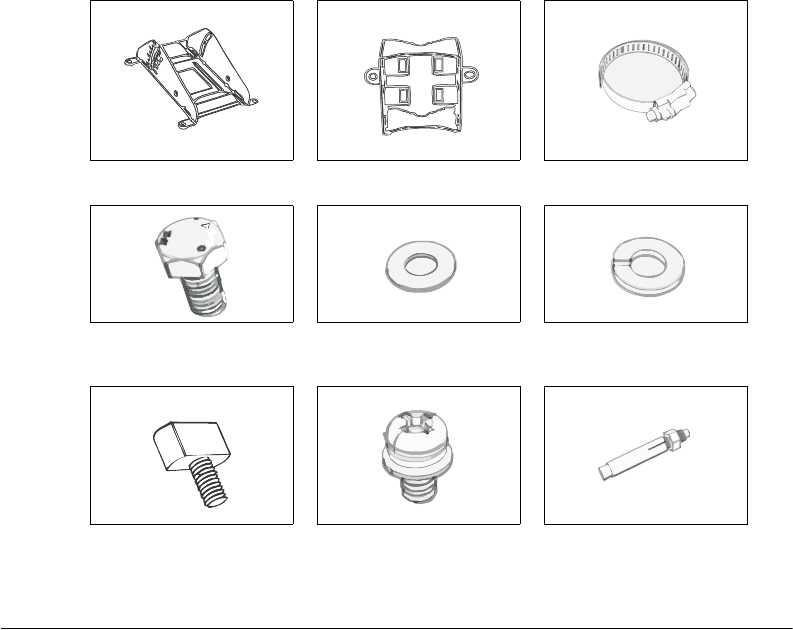
Mounting Kit Contents
Each mounting kit contains:
■Dynamic bracket
■Static bracket
■Steel clamps (2 pieces)
■Machine screws (8 pieces)
■Hex bolts (4 pieces)
■Split lock washers (4 pieces)
■Flat washers (4 pieces)
■Split lock washers (4 pieces)
■Machine screws (8 pieces)
■Thumb screws (2 pieces)
■Wall anchors (2 pieces)
Figure 1. Mounting kit contents
Dynamic bracket Static bracket Steel clamp (2 pieces)
Hex bolt (2 pieces) Flat washer (4 pieces) Split lock washer (4 pieces)
Thumb screw (2 pieces) Machine screw (8 pieces) Wall anchor with metal cone
and hex nut (2 pieces)
5
Unpacking the ZoneFlex Wireless Bridge
Package Contents
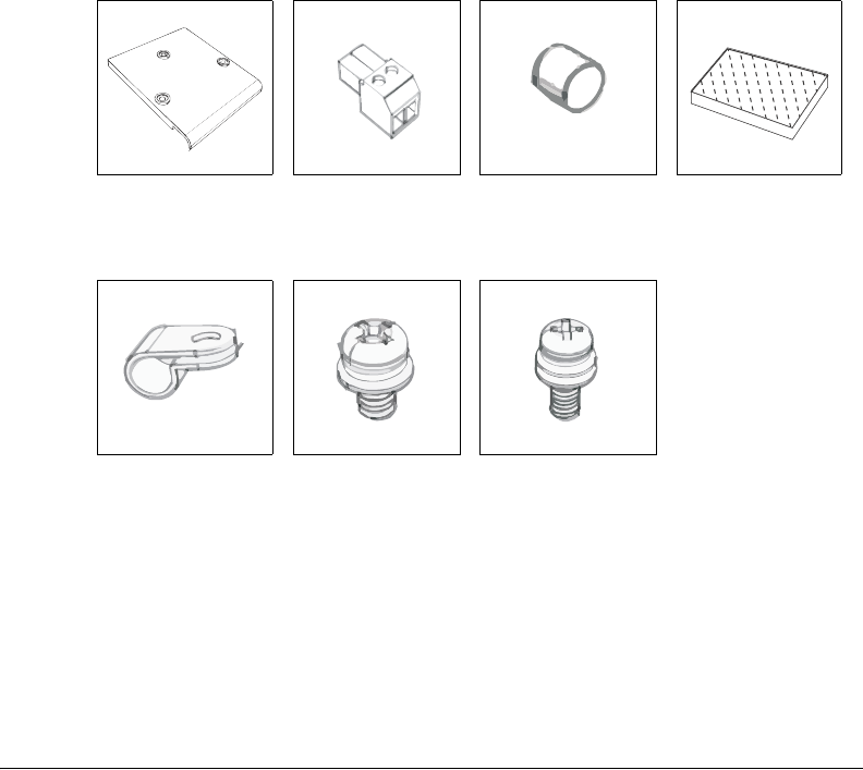
Bottom Cover and Accessories
Each bottom cover accessory bag contains:
■Bottom cover of the Wireless Bridge
■DC terminal block
■20mm x 30mm sealing strips (2 pieces)
■Sealing plug
■White P-clip cable clamps (2 pieces)
■Machine screws (2 pieces)
■Machine screws with washers (3 pieces)
Figure 2. Bottom cover and accessory package contents
Bottom cover DC terminal block Sealing Plug Sealing Strip (2
pieces)
White P-clip cable
clamp
Machine screw (2
pieces)
Machine screw with
O-ring and washer (3
pieces)

6
Before You Begin
Prepare the Required Hardware and Tools
3Before You Begin
Prepare the Required Hardware and Tools
You must supply the following tools and equipment:
■A notebook or desktop computer running Windows (2000/XP/Vista/7) with one
Ethernet card installed
■6mm flathead screwdriver
■6mm Phillips screwdriver
■10mm ratchet wrench
■3mm Phillips screwdriver (if you will be using DC power)
■Electric drill with 8mm drill bit (if mounting on a flat surface)
NOTE: At the beginning of each procedure, this guide lists the specific tools, accessories,
and equipment that you will need to complete the procedure.
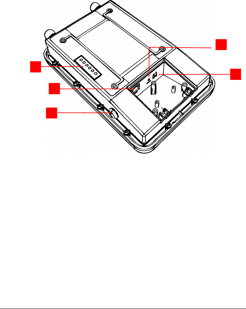
Get to Know the Hardware Features
Figure 3 and Figure 5 identify the Wireless Bridge features that are relevant to the
installation and mounting instructions that this guide provides. Before you begin the
installation process, Ruckus Wireless recommends that you become familiar with these
features.
7
Before You Begin
Get to Know the Hardware Features
Figure 3. Wireless Bridge LEDs and bottom connectors
5
1
2
4
3

8
Before You Begin
Get to Know the Hardware Features
Table 2. LEDs and bottom panel connectors
No Label Description
1LEDs See “LED Colors and What They Mean” below for more
information.
2RJ45 LAN port that supports Power over Ethernet (PoE) and 10/
100/1000 Mbps network connections
3Reset Using a pointed object (for example, a pen), press this
button to restart the Wireless Bridge or to restore it to
factory default settings:
• To restart the Wireless Bridge, press the Reset button
once.
• To restore the Wireless Bridge to factory default, press
the Reset button for six (6) seconds.
WARNING: Restoring the Wireless Bridge to factory
default settings removes all configuration changes that
you have made. These include the IP address, password,
access control list, and wireless settings. Returning the
configuration of these features to their factory default
settings may result in network connectivity issues.
412V DC In addition to PoE, you can also use direct current or DC
(from a battery, for example) to supply power to the
Wireless Bridge.
5Aiming Button Press this button to set the Wireless Bridge to Aiming
Mode. When Aiming Mode is set, the LEDs can be used
to determine signal strength. See “Aiming Mode” for
more information.
9
Before You Begin
Get to Know the Hardware Features
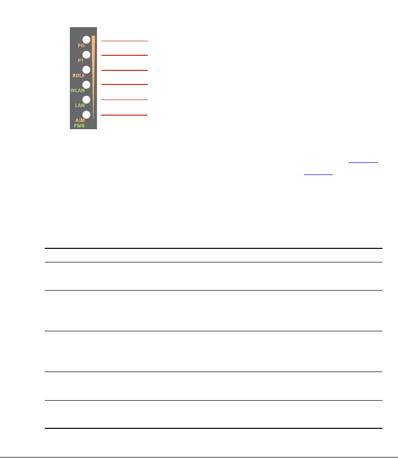
LED Colors and What They Mean
The ZoneFlex 7731 Wireless Bridge includes 6 dual color LEDs. The LEDs function in two
modes, normal operation mode and aiming mode.
Figure 4. LED Indicators
LED 1
LED 2
LED 3
LED 4
LED 5
LED 6
■For Normal Operation Mode LED states and what they indicate, refer to Tab le 3.
■For Aiming Mode LED states and what they indicate, refer to Tab l e 4.
Normal Operation Mode
In Normal Operation Mode, the WLAN LED indicator is off when disconnected, flashing
green while connecting and solid green when a connection has been established.
Table 3. Normal Operation Mode LED indicators
LED Meaning
LED 1 (AIM/PWR) Solid Green = Power on
Off = Power off
LED 2 (LAN) Solid Green = Link Up
Blinking Green = Activity
Off = Link Down
LED 3 (WLAN) Solid Green = Associated
Blinking Green = Not Associated
Off = Radio Off
LED 4 (ROLE) Solid Yellow = This unit is the root bridge
Off = This unit is the non-root bridge
LED 5 & 6 (P0 and P1) Alternating Blinking = Provisioning in process
Simultaneous Blinking = Provisioning complete; reboot pending

10
Before You Begin
Get to Know the Hardware Features
Aiming Mode
In Aiming Mode, LED 1 indicates that the Wireless Bridge is in Aiming Mode. LED
indicators 2 - 6 are used together to indicate signal strength, and should be read from
bottom to top (the higher the LEDs go, the stronger the signal).
Table 4. Aiming Mode LED indicators
LED Meaning
LED 6 Signal strength 5
LED 5 Signal strength 4
LED 4 Signal strength 3
LED 3 Signal strength 2
LED 2 Signal strength 1
LED 1 (AIM/PWR) Solid Yellow = Aiming Mode (RSSI >= 5)
Solid Green = Normal Operation Mode
Off = Off
In Aiming Mode, each LED has three states to represent different values. Solid yellow
indicates the highest value, flashing yellow indicates medium value and off indicates the
lowest value. If all six LEDs are solid yellow, the Wireless Bridge has the strongest signal
possible. If some LEDs are flashing yellow or off, reposition the Wireless Bridge to achieve
a better signal. For more detailed information on signal strength levels, see “RSSI values
of LED indicators” on page 57.
Push Buttons
The ZoneFlex 7731 includes two push buttons:
■A recessed factory default reset button (located inside the bottom panel)
■A large blue Aiming Mode button that sets the bridge to Aiming Mode (located on
the outside of the unit)
To reset the unit to its factory defaults, press and hold the Reset button for six (6) seconds.
Press and hold the blue Aiming button for four (4) seconds to initiate aiming between the
root and non-root bridge.
CAUTION: Resetting the ZoneFlex 7731 to its factory defaults will result in loss of all
configuration settings, including the pre-provisioning (pairing of the root and non-root
bridge) settings that were enabled prior to shipping. If you do need to reset to defaults,
you will need to re-provision the pair.
11
Before You Begin
Get to Know the Hardware Features
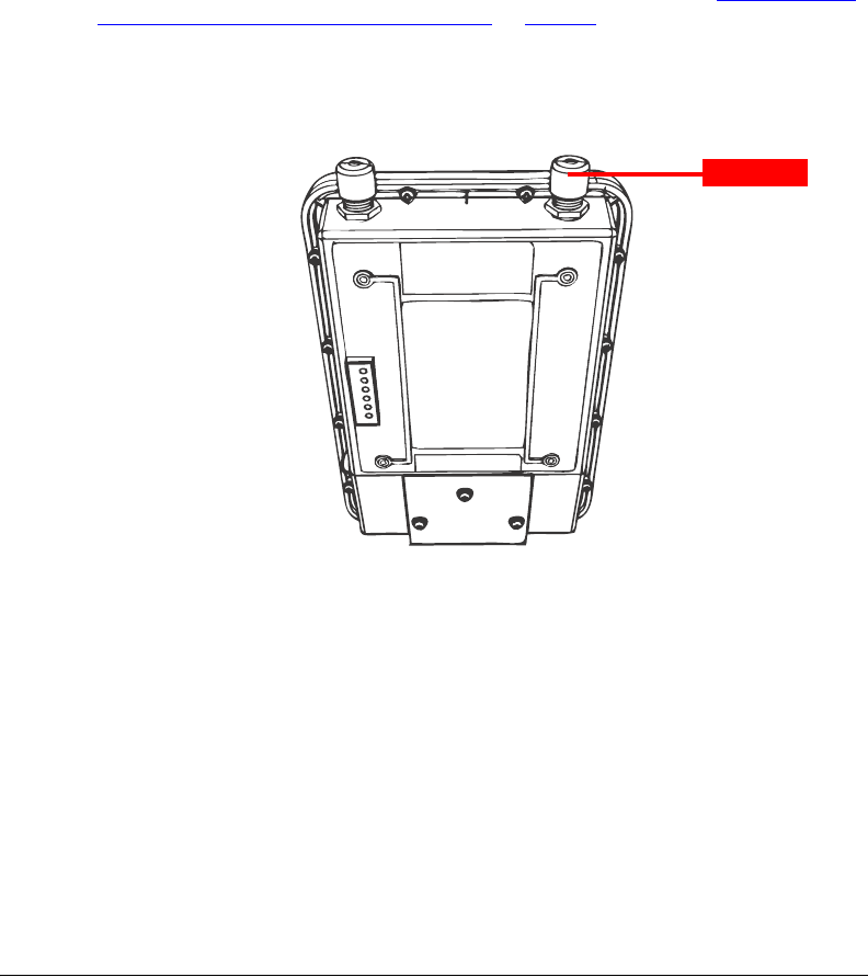
External Antenna Connectors
The ZoneFlex 7731 Wireless Bridge includes one purpose designed internal directional
antenna. If you want to extend the range of your wireless network, you can connect an
external high gain 5GHz antenna to the two standard N-type external antenna connectors
on the top panel of the Wireless Bridge. The antenna must have a gain of less than 23dBi
to comply with FCC and CE regulations. For more information, refer to “Mounting and
Connecting the External Antenna (Optional)” on page 56.
Figure 5. The antenna connectors are protected by metal caps
Metal Cap
12
Pre-Installation Configuration
Summary of Pre-Installation Tasks
4Pre-Installation Configuration
This section describes the configuration procedures required before you begin mounting
the bridges in their permanent locations.
Summary of Pre-Installation Tasks
1. Supply power to both units.
2. Access the units using an administrative computer.
3. Set the country code to your current location.
4. Change other configuration settings (optional).
5. Use the SpeedFlex tool built into the Web interface to test the link between the units.
NOTE: If you purchased the Wireless Bridge in the United States, the country code is
fixed to “United States” at the factory and is not user configurable. If not, you must set
the country code to your location prior to mounting to ensure compliance with national
regulatory requirements.
CAUTION: If changing the Country Code over the air, you will need to configure the
remote unit first followed by the local unit, to avoid loss of connectivity.
In addition to setting the country code (required), the following optional configuration
settings may be changed at this time:
■Change the device name and SSID
■Manually assign static IP addresses
■Enable SNMP or FlexMaster network management
■Configure security settings
■Configure management VLAN
CAUTION: Changing any settings of either the root or non-root bridge will require that
you also change the same settings on the other device.
To customize any of these settings before deploying the bridge pair, you will need to
connect an administrative computer directly to each ZoneFlex 7731 using the unit’s default
IP address, and provide power using either DC power or Power over Ethernet before you
can access the unit’s Web interface.
The default IP addresses for the root and non-root bridge are as follows:
■Root Bridge: 192.168.2.1
■Non-Root Bridge: 192.168.2.254
13
Pre-Installation Configuration
What You Will Need
NOTE: In general, you should first make configuration changes to the Root bridge,
followed by the Non-Root bridge.
What You Will Need
Before starting with the configuration task, make sure that you have the following require-
ments ready:
■An administrative computer running Microsoft Windows (2000/XP/Vista/7)
■Mozilla Firefox 2.0 (or later) or Microsoft Internet Explorer 6.0 (or later) installed on the
administrative computer
■Two Ethernet cables
■PoE injector (if not supplied with the Wireless Bridge, you can purchase a third party
802.3af-compliant PoE injector or switch)
■6mm Phillips screwdriver
If you are planning to power the Wireless Bridge using a 12v DC connection, you will also
need the following:
■One 3.1mm-3.3mm UL1185 (80°, 300V) single shielded DC cable
■12v DC, 1A DC power source (for example, a battery)
■3mm Phillips screwdriver
Access the Web Interface
CAUTION: Do not attempt to access the Web interface of both ZoneFlex 7731 units at
the same time by connecting both to the same Layer 2 switch or to the same broadcast
domain on a live network. This will cause a network loop, which can disrupt your entire
network.
Step 1: Connect the Power and Ethernet Cables
The procedure for connecting cables to the Wireless Bridge depends on the power source
that you will be using. You can do one of the following:
■Use Power Over Ethernet
■Use DC Power
14
Pre-Installation Configuration
Access the Web Interface
NOTE: You only need to connect one type of power source at this point, even if you are
planning to use both PoE and DC power in your final deployment.
Use Power Over Ethernet
1. Take out the PoE injector and the power adapter from the Wireless Bridge package.
2. Obtain two Ethernet cables.
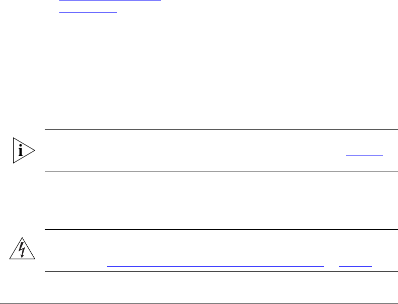
3. Connect one end of one Ethernet cable to the AP/BRIDGE port on the PoE injector,
and then connect the other end to the RJ45 port on the ZoneFlex 7731.
4. Connect one end of the other Ethernet cable to the NETWORK port on the PoE
injector.
5. Connect the power jack to the DC 48V IN connector on the PoE injector, and then
plug the power adapter into a power source. The single LED on the PoE injector turns
green.
6. Check the power LED on the ZoneFlex 7731 to ensure power is being supplied to the
bridge.
Figure 6. Connect the Ethernet cables and power adapter to the PoE injector
To Adm in
Computer
To Bridge
To AC P ow er Source
You have completed connecting the Wireless Bridge to a PoE power source.
Use DC Power
To use DC to power the Wireless Bridge, you need to connect a DC cable (not supplied
with the Wireless Bridge) to the DC terminal block.
1. Take out the DC terminal block from the small plastic bag that contains the bottom
cover of the Wireless Bridge.
15
Pre-Installation Configuration
Access the Web Interface
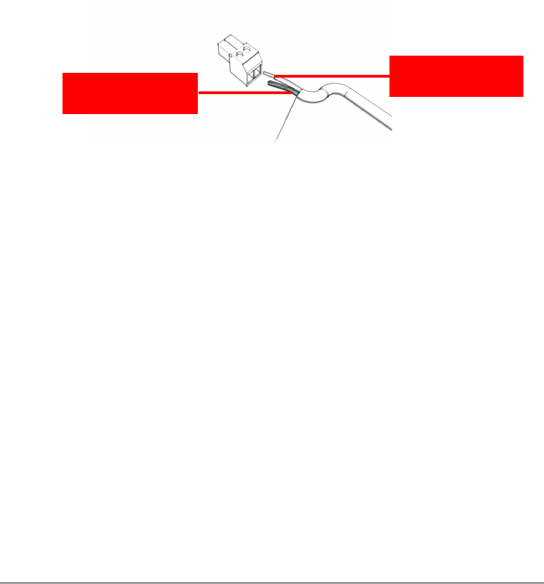
2. Connect the DC cable’s ground wire to V- terminal. If you are looking at the terminal
block with the wiring terminal screws on top, the V- terminal is on the left side.
3. Connect the DC cable’s +12v DC wire to the V+ terminal. If you are looking at the
terminal block with the wiring terminal screws on top, the V+ terminal is on the right
side.
Figure 7. Connect the ground wire to the V- terminal and the +12v DC wire to the V+
terminal
Ground Wire to
V- Terminal
12V DC Wire to
V+ Terminal
4. Using a 3mm Phillips screw, tighten the wiring terminal screws. Screw torque value must
be 20.5 mN-m ± 2 mN-m.
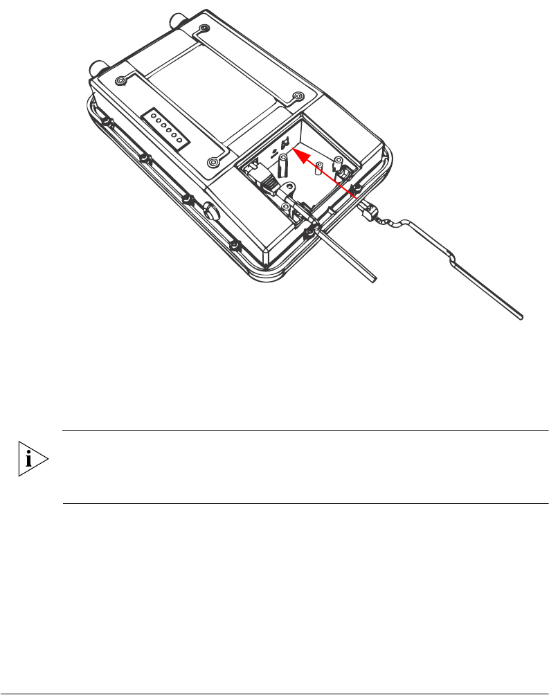
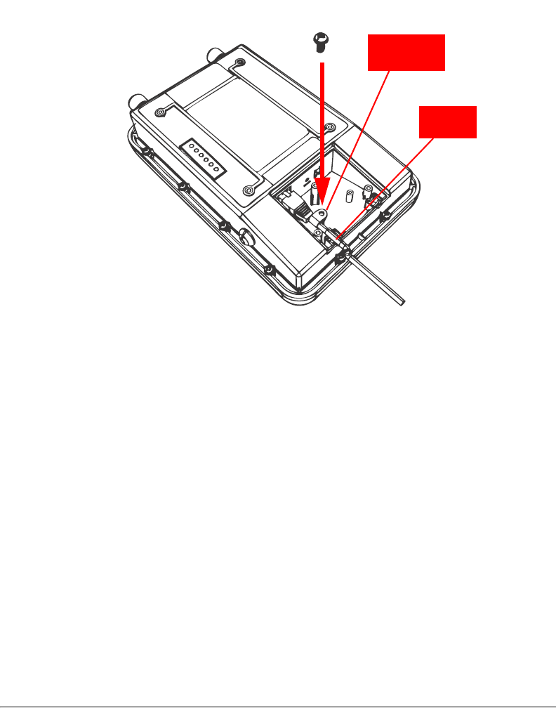
5. Connect the DC terminal block to the 12V DC port on the Wireless Bridge.
16
Pre-Installation Configuration
Access the Web Interface
Figure 8. Connect the DC terminal block to the 12V DC port
6. Connect the DC cable to a DC power source (for example, a battery).
You have completed connecting the Wireless Bridge to a DC power source.
Step 2: Prepare the Administrative Computer
NOTE: The following procedure is applicable if the administrative computer is running
Windows XP or Windows 2000. If you are using a different operating system, refer to the
documentation that was shipped with your operating system for information on how to
modify the computer’s IP address settings.
1. On your Windows XP or Windows 2000 computer, open the Network Connections (or
Network and Dial-up Connections) control panel according to how the Start menu is
set up:
• On Windows XP, click Start > Control Panel > Network Connections.
• On Windows 2000, click Start > Settings > Network Connections.
2. When the Network Connections window appears, right-click the icon for Local Area
Connection, and then click Properties.

17
Pre-Installation Configuration
Access the Web Interface
NOTE: Make sure that you configure the Local Area Connection properties, not the
Wireless Network Connection properties.
3. When the Local Area Connection Properties dialog box appears, select Internet
Protocol (TCP/IP) from the scrolling list, and then click Properties. The Internet
Protocol (TCP/IP) Properties dialog box appears.
4. Write down all of the currently active network settings. You will need this information
later when you restore your computer to its current network configuration.
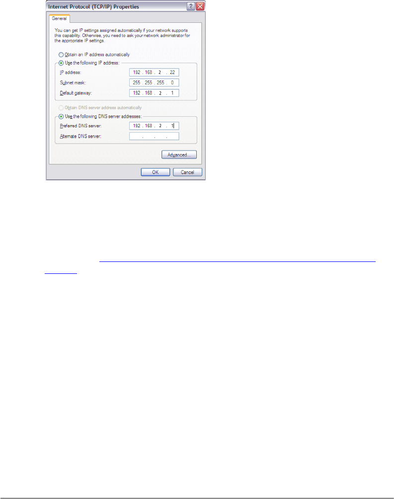
5. Click Use the following IP address, and then configure the IP address settings with
the values listed in Table 5. For a sample configuration, refer to Figure 9.
Table 5. Configure your computer’s IP address settings
IP address 192.168.2.22 (or any address in the 192.168.2.x
network—with the exception of 192.168.2.1 and
192.168.2.254 which will be used by the bridges)
Subnet mask 255.255.255.0
Default gateway 192.168.2.1
Preferred DNS server 192.168.2.1
You can leave the Alternate DNS server box blank.
6. Click OK to save your changes and close the TCP/IP Properties dialog box.
7. Click OK again to close the Local Area Connection Properties dialog box.
Windows saves the IP address settings that you have configured.
18
Pre-Installation Configuration
Access the Web Interface
Figure 9. Sample configuration in the Internet Protocol (TCP/IP) Properties dialog box
Step 3: Connect the Wireless Bridge to the Admin
Computer
If you have not already done so, connect the admin computer to the ZoneFlex 7731 using
an Ethernet cable, or two Ethernet cables and a PoE injector if you are using Power over
Ethernet (see “Connect the Ethernet cables and power adapter to the PoE injector” on
page 14).
Step 4: Log In to the Web Interface
1. Open a Web browser window from the admin computer.
2. In the address or location bar, type the following address:
Root Bridge: http://192.168.2.1
Non-Root Bridge: http:/192.168.2.254
3. Press <Enter> on the keyboard to connect to the Wireless Bridge’s Web interface. A
security alert message appears.
4. Click Yes or OK (depending on the browser) to continue. The Wireless Bridge’s login
page appears.

19
Pre-Installation Configuration
Access the Web Interface
Figure 10. The ZoneFlex Wireless Bridge login page
5. In User name, type super.
6. In Password, type sp-admin.
7. Click Login. The Web interface appears, displaying the Status > Wireless page.
20
Pre-Installation Configuration
Access the Web Interface
Figure 11. Ruckus ZoneFlex 7731 Wireless Bridge Status :: Wireless page
8. Continue to “Step 5: Change the Country Code”.
Step 5: Change the Country Code
Change the Country Code setting to your location and reboot the bridge for updates to
take effect.
CAUTION: If changing the Country Code after the pair has been mounted, you will need
to configure the remote unit first followed by the local unit, to avoid loss of connectivity.
NOTE: If you purchased the Wireless Bridge in the United States, this value is fixed to
“United States” at the factory and is not user configurable.
If you purchased the Wireless Bridge outside of the United States, verify that the value is
set to your country or region. Selecting the correct country code ensures that the Wireless
Bridge uses only the radio channels allowed in your country or region.
1. On the Configuration > Wireless page, select your location from the Country Code
menu.
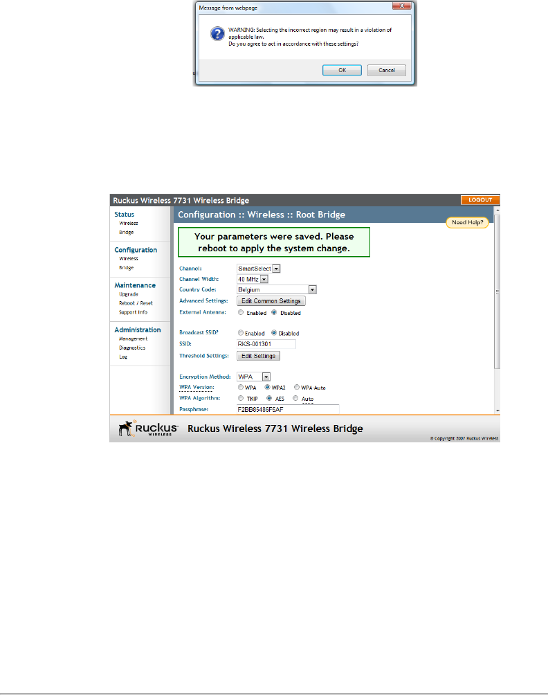
2. The following warning message appears:
21
Pre-Installation Configuration
Access the Web Interface
Figure 12. Country code warning message
3. Click OK to continue.
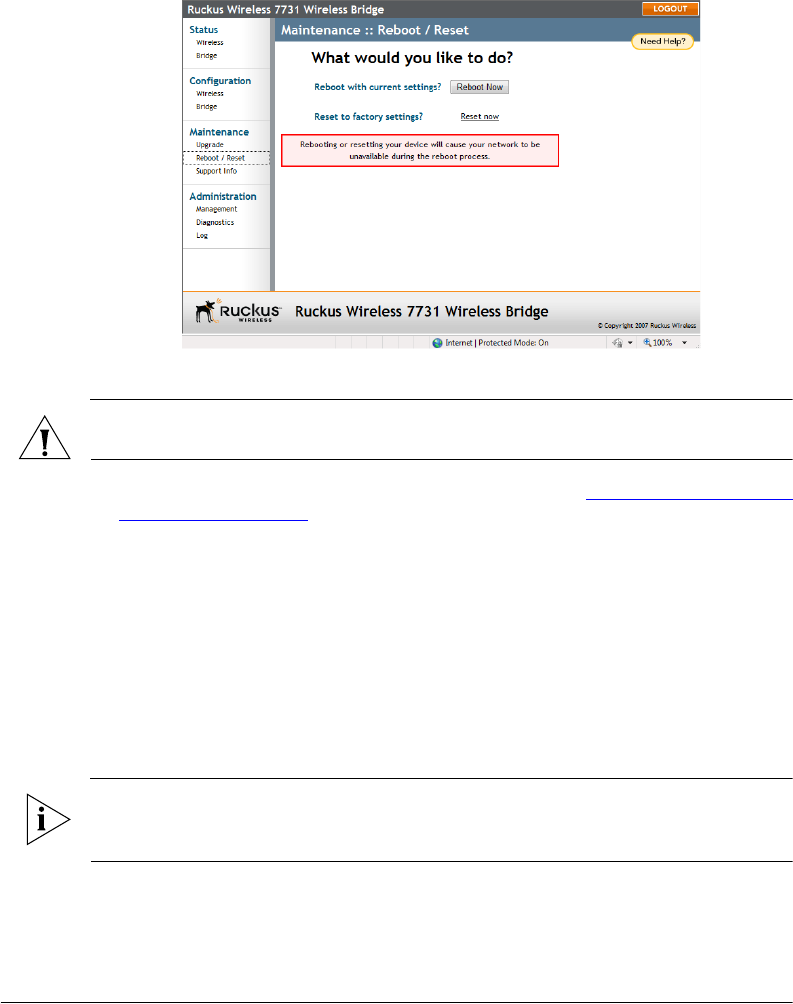
4. Click Update Settings to confirm changes.
5. A message indicating that your parameters were saved and a reboot is required
appears.
Figure 13. Your parameters were saved; reboot required
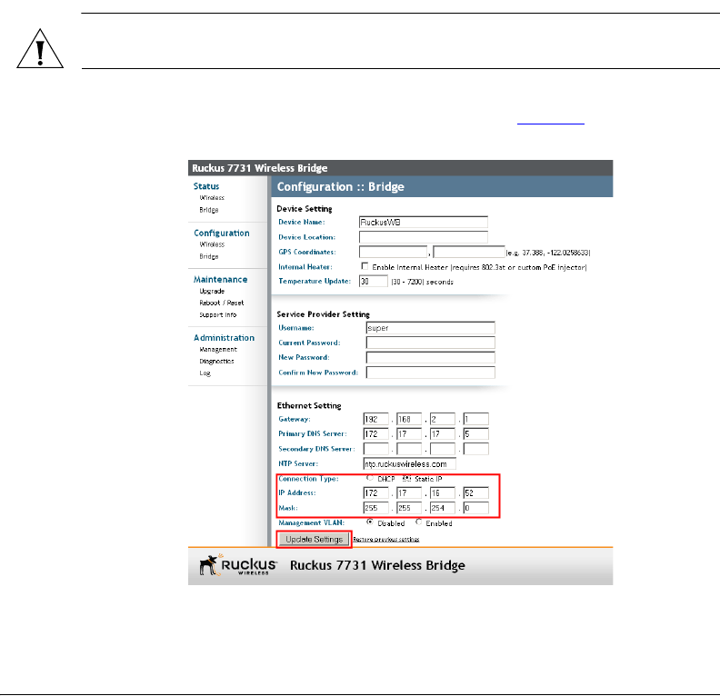
6. Go to Maintenance > Reboot / Reset, and click Reboot Now.
22
Pre-Installation Configuration
Access the Web Interface
Figure 14. Reboot the wireless bridge to apply country code change
7. When the reboot is completed, log in again to continue making configuration changes.
CAUTION: Do not change the Channel setting until after the Country Code has been set
for both units.
8. You have completed setting the Country Code. Continue to “Step 6: Change Optional
Configuration Settings”.
Step 6: Change Optional Configuration Settings
This section describes optional configuration settings that you can change prior to
beginning the physical installation. These settings include:
■IP address
■Device name and location
■SSID, encryption method and passphrase
■Management VLAN
■Network management method
NOTE: Ruckus Wireless recommends leaving these settings at their default values until
installation of both bridge units is complete. Note that any changes made to the root
bridge settings must also be performed on the non-root bridge.
23
Pre-Installation Configuration
Access the Web Interface
Change the IP Address
By default, the Ruckus Wireless ZoneFlex 7731 Wireless Bridge units come with DHCP
enabled and will automatically acquire an IP address from a DHCP server if one is
discovered on the network. If no DHCP server is found, the Root bridge and Non-Root
bridge have pre-configured IP addresses assigned to prevent conflict. The default IP
addresses for the two units are as follows:
Root Bridge: 192.168.2.1
Non-Root Bridge: 192.168.2.254
If you want to change the IP address of either or both of the pair, you can manually assign
a static IP address on the Configuration > Bridge page in the Web interface.
CAUTION: If you assign static IP addresses, you must ensure that the IP addresses
assigned are unique network-wide to prevent conflict.
To assign a static IP address, select the Static IP radio button after “Connection Type,”
and enter the desired address and subnet mask as shown in Figure 15.
Figure 15. Changing the IP address
Click Update Settings to confirm the changes.
24
Pre-Installation Configuration
Access the Web Interface
You will need to re-enter the new IP address in your browser and login again to continue
editing configuration options. The non-root bridge will automatically detect the new IP
address of the root bridge and attempt to associate with it.
NOTE: This process may take several minutes. Do not unplug the ZoneFlex 7731 while
it is updating its IP address.
Change Device Name, Location, User Name and Password
In addition to the IP address, you can also change the device name, location, login name
and password on this page.
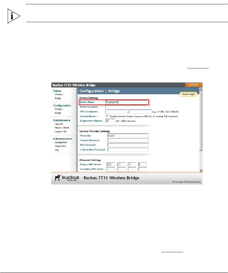
1. On the Configuration > Bridge page, replace the existing device name (default:
“RuckusWB”) with your preferred name for the device, as shown in Figure 16.
Figure 16. Changing the device name, location, user name and password
2. Enter a Device Location to easily identify the location of the unit.
3. Enter GPS coordinates for location management via FlexMaster.
4. Change the User Name and Password used to access the Web interface.
5. Click Update Settings to confirm changes.
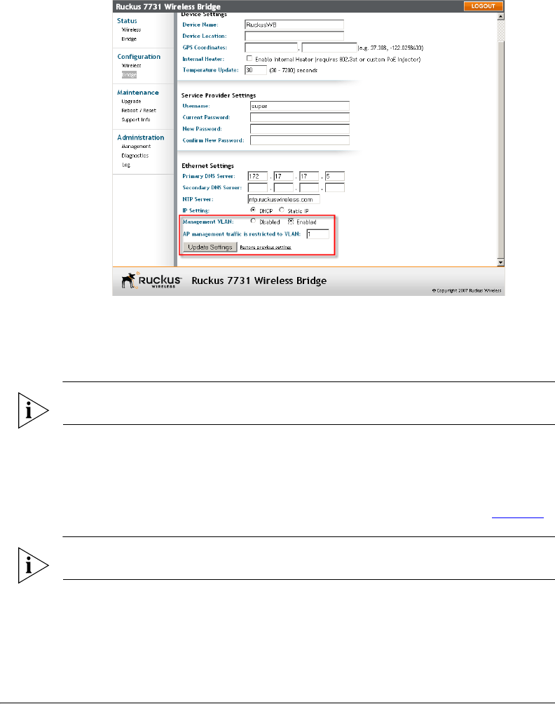
Enable Management VLAN
If you would like to enable wireless bridge traffic to be part of an existing network
management VLAN, you can set the Wireless Bridge’s management VLAN to match your
network via the Configuration > Bridge page, as shown in Figure 17.
25
Pre-Installation Configuration
Access the Web Interface
Figure 17. Enable Management VLAN
Click Enable next to Management VLAN and enter the VLAN ID in the field below. Click
Update Settings to confirm changes.
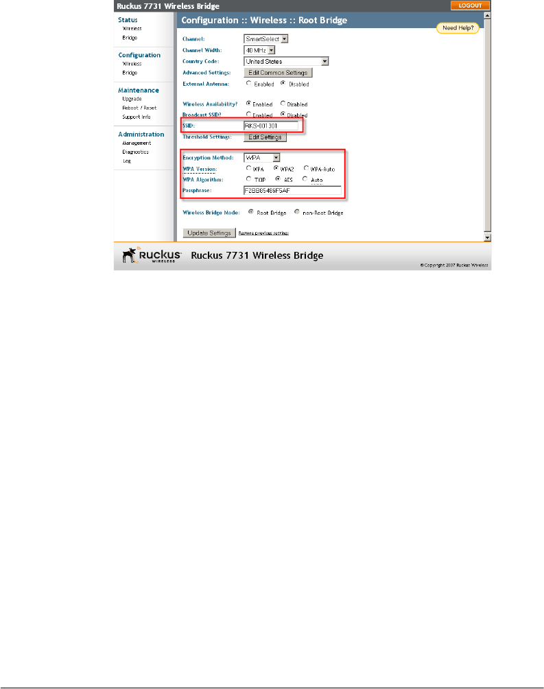
Change SSID and Encryption Method
NOTE: If these changes are made after the units are mounted, make the changes to the
remote unit, whether it be Root or Non-Root, first to avoid loss of connection.
At factory default, the Root bridge will have a unique SSID and WPA-PSK passphrase which
matches that of the Non-Root bridge. Changing these values will cause the two bridge
units to be unable to communicate with one another unless the values match. To change
the SSID, encryption method and passphrase, open the Configuration > Wireless page.
Enter a unique SSID in the SSID field and click Update Settings, as shown in Figure 18.
NOTE: Write down all the entries made in this step, as you will need to reenter them later
when you configure the non-root bridge.
26
Pre-Installation Configuration
Access the Web Interface
Figure 18. Change SSID, encryption method and passphrase
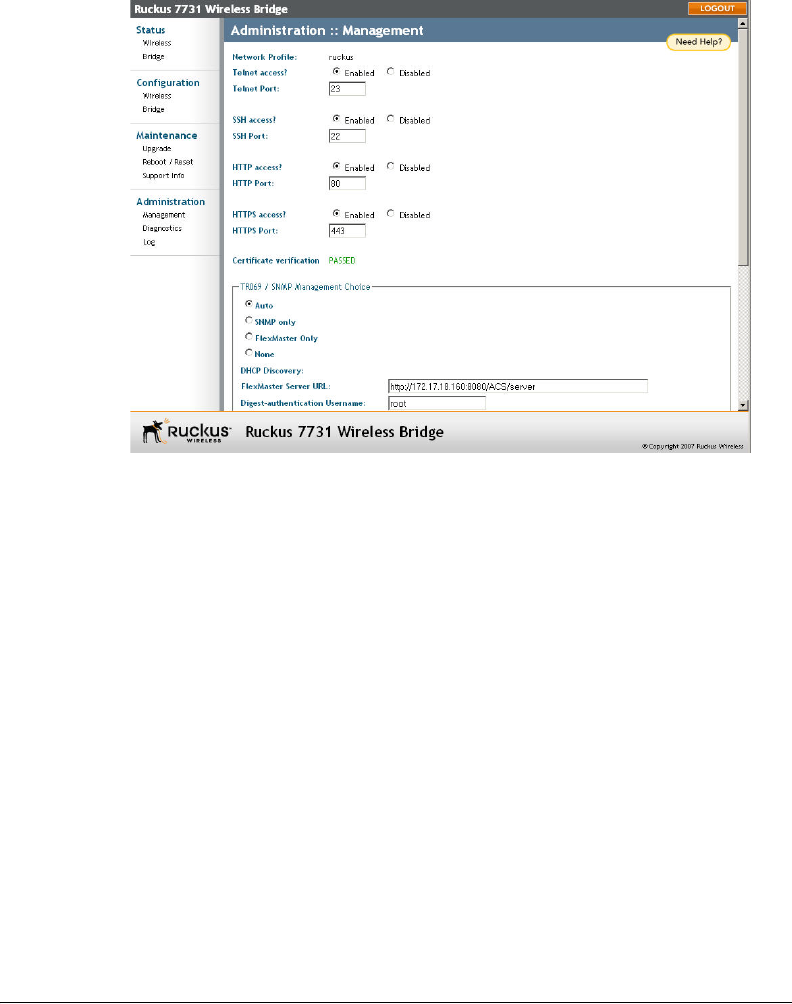
Configure Network Management Settings
The ZoneFlex 7731 Wireless Bridge can be managed remotely using either SNMP or
Ruckus Wireless FlexMaster (TR069 protocol) server. To access the network management
settings, click on Administration > Management.
By default, the network management method is set to Auto, meaning that the ZoneFlex
7731 will be managed by FlexMaster server if available, and by SNMP if no FlexMaster
server is found on the network.
27
Pre-Installation Configuration
Access the Web Interface
Figure 19. Administration :: Management page
If you want to manage the Wireless Bridge using SNMP even when a FlexMaster server is
available, select SNMP only under “TR069/SNMP Management Choice,” then enter the
Read-Only/Read-Write Community information, along with the SNMP Trap server IP
address in the appropriate spaces. Click Update Settings to confirm changes.
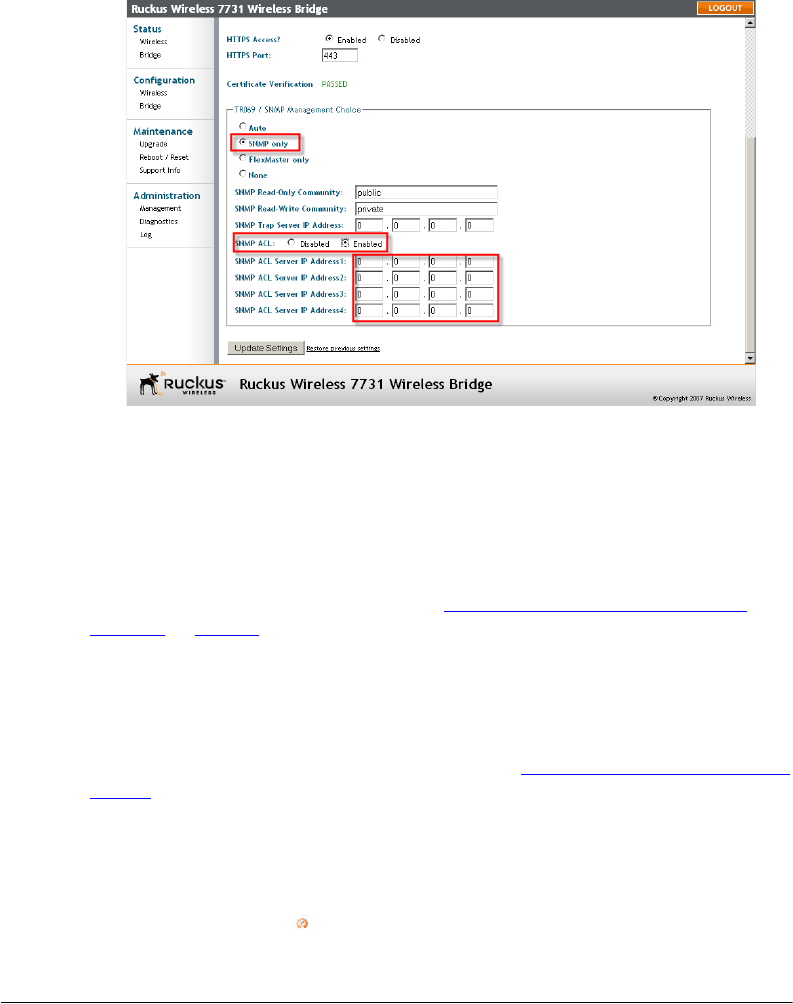
The SNMP ACL option allows you to restrict the number of devices that can access the
Wireless Bridge for management purposes. If the SNMP ACL (access control list) is
disabled, then any device on the network will be able to access the Wireless Bridge using
SNMP commands.
28
Pre-Installation Configuration
Access the Web Interface
Figure 20. Enable SNMP Access Control List
To restrict SNMP access to the Wireless Bridge:
1. On the Administration > Management page, click on SNMP Only under the heading
“TR069 / SNMP Management Choice.”
2. Select Enabled next to the “SNMP ACL” line.
3. Enter the IP addresses of up to 4 SNMP servers.
4. Click Update Settings to confirm changes.
For Flexmaster server management, refer to “(Optional) Set the FlexMaster Server
Address” on page 60.
Step 7: Change Non-Root Bridge Configuration Settings
Repeat steps 1-6 for the Non-Root bridge for any changes you made to the Root bridge
settings. If you did not make any changes, you only need to repeat step 1 to provide power
and Ethernet to the non-root bridge, then proceed to Step 8: Test the Link Between the
Bridges. Note that setting the Country Code for the Root Bridge requires that the same
setting be made for the Non-Root Bridge.
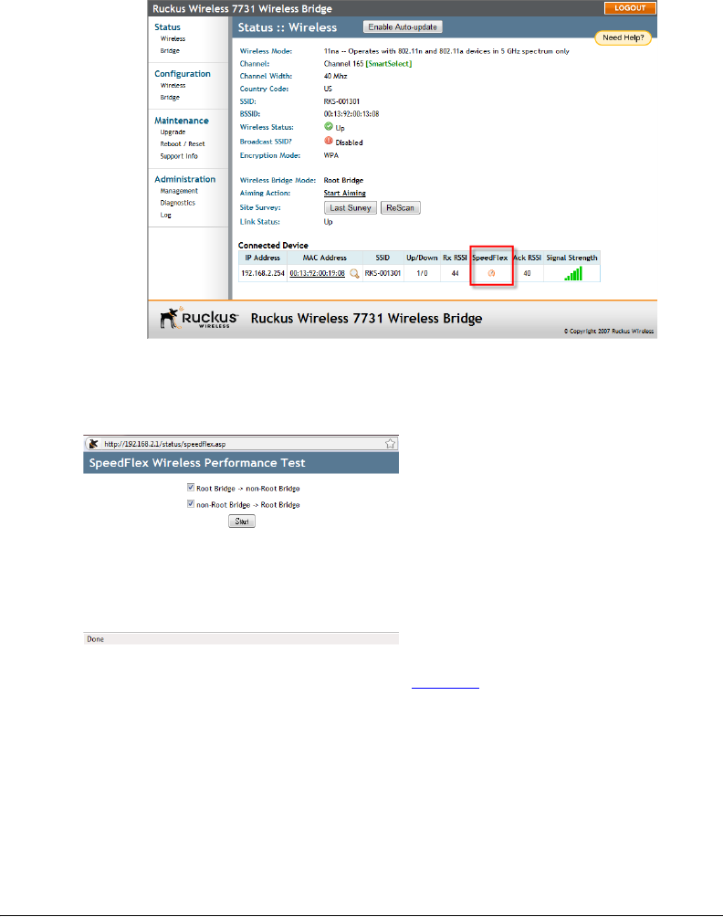
Step 8: Test the Link Between the Bridges
The SpeedFlex utility lets you test the data transfer speeds between the two bridge units.
Click the SpeedFlex icon on the home page (Status > Wireless) to begin testing.
29
Pre-Installation Configuration
Access the Web Interface
Figure 21. Launch the SpeedFlex utility to test the link between bridges
The SpeedFlex utility opens in another window. Press Start to begin testing both uplink
and downlink performance, or deselect one of the check boxes to test only one direction.
Figure 22. SpeedFlex Wireless Performance Test
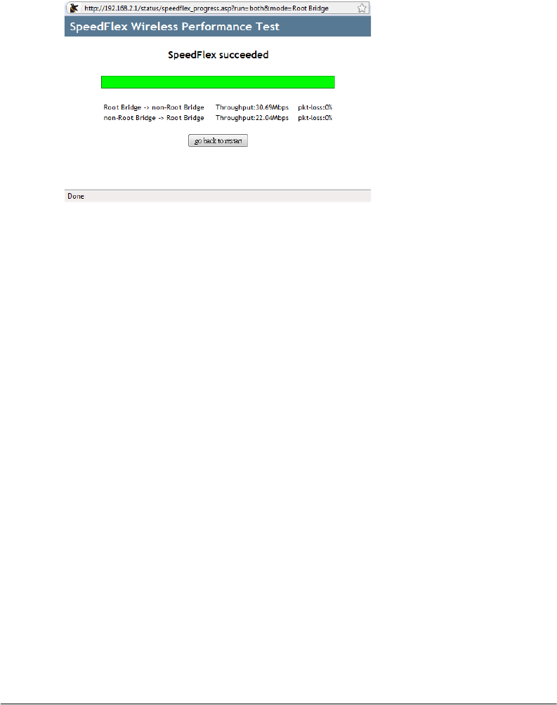
Performing both tests may take several minutes. When the test is finished, throughput and
packet loss results are displayed, as shown in Figure 23.
30
Pre-Installation Configuration
Access the Web Interface
Figure 23. SpeedFlex Results page
You have finished accessing and testing the link between the ZoneFlex 7731 Wireless Point
to Point Bridge pair.
Step 9: Disconnect the Wireless Bridge from the
Administrative Computer
1. Disconnect the Wireless Bridge from the power source (either from the PoE injector or
DC power source).
2. Verify that the PWR LED on the back of the Wireless Bridge is off.
3. Disconnect the Ethernet cable from the administrative computer’s Ethernet port.
Step 10: Restore the Administrative Computer’s Network
Settings
1. On your Windows XP or Windows 2000 computer, open the Network Connections (or
Network and Dial-up Connections) control panel according to how the Start menu is
set up:
• On Windows XP, click Start > Control Panel > Network Connections.
• On Windows 2000, click Start > Settings > Network Connections.
2. When the Network Connections window appears, right-click the icon for Local Area
Connection, and then click Properties.
3. When the Local Area Connection Properties dialog box appears, select Internet
Protocol (TCP/IP) from the scrolling list, and then click Properties. The TCP/IP
Properties dialog box appears.
4. Restore the computer’s network settings by typing the original IP address settings in
the TCP/IP Properties dialog box.
5. On the TCP/IP Properties dialog box, click OK to close it.
31
Provisioning and Associating the Wireless Bridge Pair (Optional)
Auto Provisioning
6. Click OK again to close the Local Area Connection Properties dialog box.
You are now ready to begin the physical installation.
5Provisioning and Associating the Wireless
Bridge Pair (Optional)
Ruckus Wireless ZoneFlex 7731 Wireless Bridge units come in pre-provisioned pairs, and
they will automatically associate with one another as soon as they are powered on.
Therefore in most situations, you will not need to provision or associate the Root and Non-
Root bridge.
However, if you need to reset either unit to its factory defaults, replace one of the units, or
decide to switch which unit acts as the Root and the Non-Root bridge, you can use the
following procedure to re-provision (re-assign one unit as the Root and one as the Non-
Root bridge), and re-associate the link between the pair.
Auto Provisioning
The auto provisioning process is used to automatically designate one of the ZoneFlex 7731
units as the Root bridge and the other as the Non-Root bridge.
NOTE: The ZoneFlex 7731 Wireless Bridge units are shipped already paired so auto
provisioning will not be needed in the field unless it becomes necessary to restore factory
default settings.
Conduct the following procedure to automatically provision the root and non-root
bridge:
1. Reset both units to their factory defaults, by either:
■Pressing and holding the Reset button in the bottom panel for at least 6 seconds
■Click Reset Now next to “Reset to factory settings?” on the Maintenance > Reboot/
Reset page in the Web interface
CAUTION: Do not reset the units to factory defaults once they are mounted in their
permanent locations.
2. Connect two units together directly via an Ethernet cable and provide power to both
units (you can power up and then connect OR connect and then power up both units).
3. The LAN LED on both units (LED 2) should be solid green, indicating that the units are
connected to each other. At this point, if both units have been reset to factory defaults,
neither has yet been specified as Root or Non-Root.
32
Provisioning and Associating the Wireless Bridge Pair (Optional)
Manual Provisioning Using the Web Interface
4. Once both units are powered on and physically connected, LED 5 and 6 (labeled P0
and P1) on both units begin alternately blinking, indicating that provisioning is in
process. This process takes about 10 to 20 seconds.
5. Simultaneous rapid blinking of these two LEDs indicates that provisioning is complete.
6. After provisioning is complete, LED 4 (ROLE) indicates which unit is the Root and Non-
Root unit. The ROLE LED is solid yellow for the Root bridge while the Non-Root bridge’s
ROLE LED is OFF.
7. Take note of which unit is the Root bridge and which is the Non-Root bridge.
8. When the auto provisioning process completes, a reboot is triggered by disconnecting
the Ethernet cable. During the reboot only the bottom LED, PWR is lit. Once the reboot
completes you will see activity on the WLAN LED, indicating wireless communication
between the pair.
9. Because the units were reset to factory defaults before provisioning, you will need to
re-set the Country Code to your location on both units (unless purchased in the United
States). See “Step 5: Change the Country Code” on page 2-20.
Manual Provisioning Using the Web Interface
The ZoneFlex 7731 Wireless Bridge units can also be manually provisioned using the Web
interface.
The procedure for Web based provisioning is as follows:
1. Log in to the Web interface of the unit that you will designate as the Root bridge.
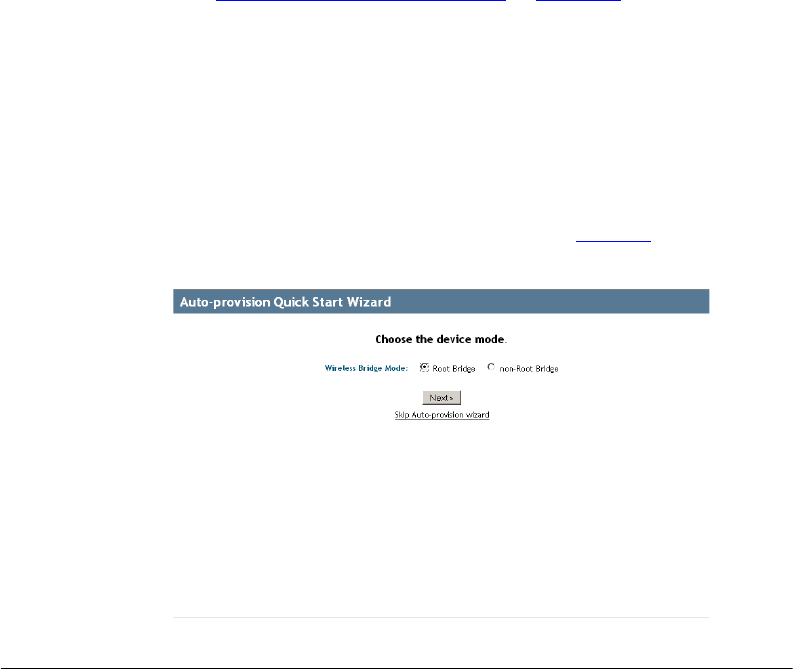
2. If the unit has been reset to factory defaults, the Provisioning Quick Start Wizard will
launch automatically immediately after login, as shown in Figure 24.
Figure 24. Provisioning Quick Start Wizard
33
Provisioning and Associating the Wireless Bridge Pair (Optional)
Manual Provisioning Using the Web Interface
3. Select Root Bridge and click Next to continue.
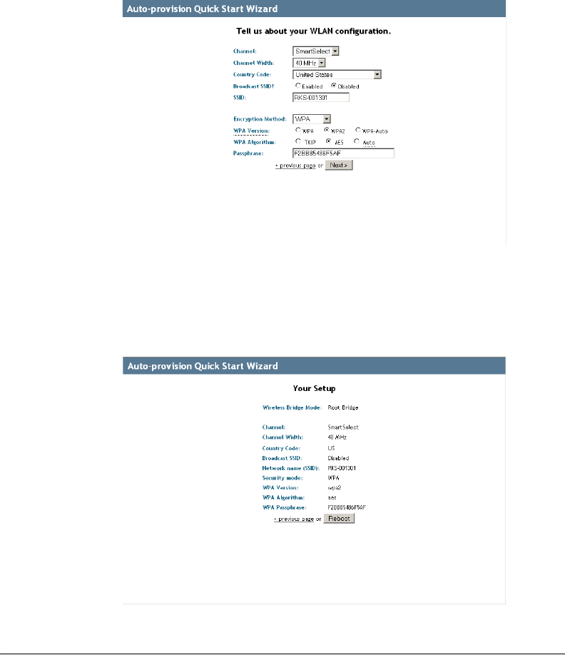
4. Adjust settings on the WLAN configuration page if necessary, and click Next to
continue.
Figure 25. WLAN Configuration options
5. Set the Country Code to your location. Do not change any of the settings under
Channel, Channel Width, or Broadcast SSID at this time.
6. Write down the SSID, encryption settings and Passphrase, as you will need to enter
these values when you provision the Non-Root bridge.
Figure 26. Reboot after completing the Provisioning Wizard
7. Click Reboot to confirm changes and reboot the bridge.
34
Provisioning and Associating the Wireless Bridge Pair (Optional)
Associating
8. Repeat steps 2-7 for the non-root bridge, selecting Non-Root Bridge on Step 3, and
making sure you enter the same values on the WLAN Configuration page as those of
the root bridge.
You have finished manually provisioning the wireless bridge pair.
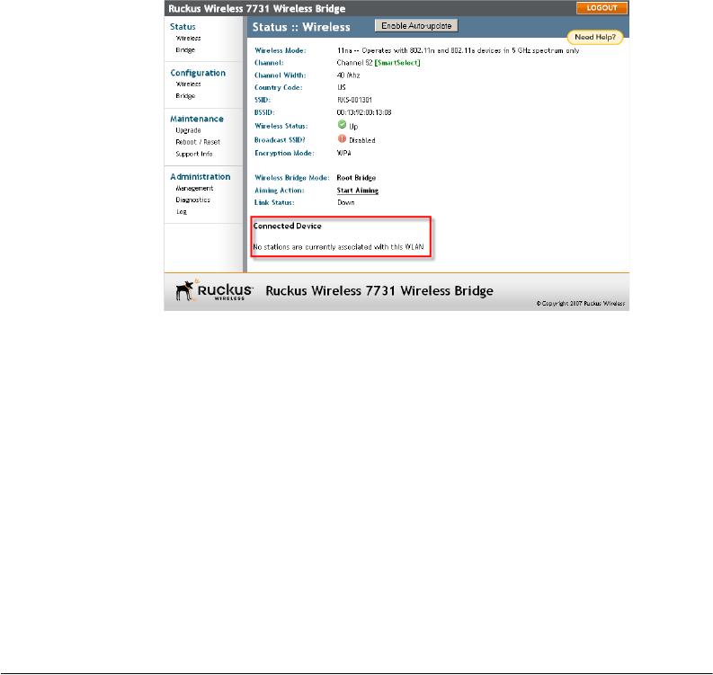
Associating
Once the bridge pair has been provisioned, verify that they have associated with one
another. If no association between the two bridge units has been established, the following
will be displayed:
Figure 27. No association established
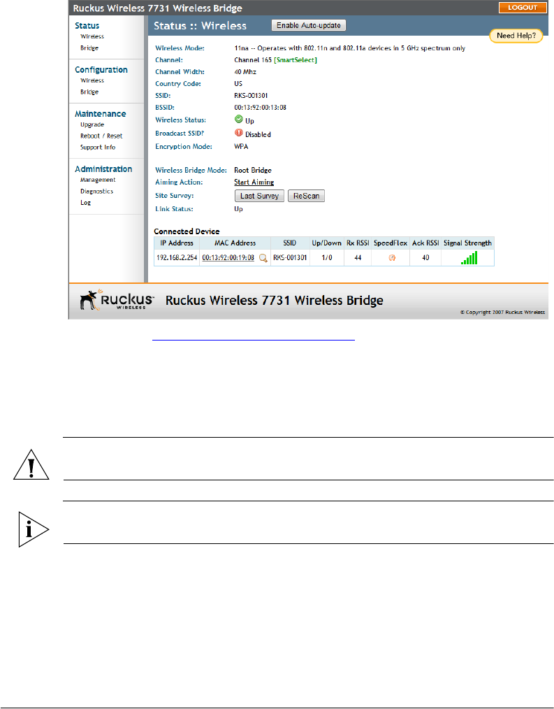
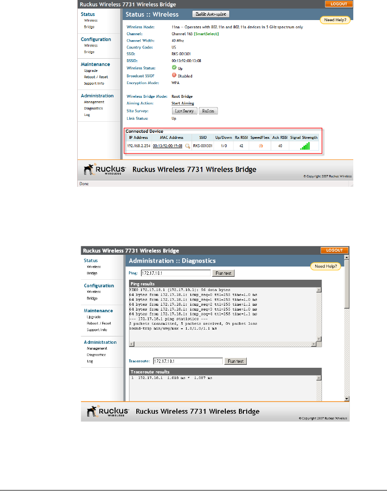
The units will automatically associate with one another after about 1 to 2 minutes. Once
the association is complete, the page will refresh and the Connected Device information
will be displayed, as shown:
35
Provisioning and Associating the Wireless Bridge Pair (Optional)
Associating
Figure 28. Association established
If no association is established after a few minutes, the Web interface provides several
tools for diagnosing the problem, which can be found on the Administration > Diagnos-
tics page. Tools include Ping, Traceroute, Show ARP Table and Show FDB Table.
Figure 29. Administration :: Diagnostics page

36
Physical Installation
Prepare the Required Hardware and Tools
6Physical Installation
Prepare the Required Hardware and Tools
You must supply the following tools and equipment:
■A notebook or desktop computer running Windows XP/2000/Vista and installed with
one Ethernet card
■6mm flathead screwdriver
■6mm Phillips screwdriver
■10mm ratchet wrench
■3mm Phillips screwdriver (if you will be using DC power)
■Electric drill with 8mm drill bit (if mounting on a flat surface)
Determine the Optimal Mounting Location and
Orientation
The location and orientation that you choose for the Wireless Bridge play a critical role in
the performance of your wireless network. In general, Ruckus Wireless recommends
installing Wireless Bridges away from obstructions and sources of interference and
ensuring that the Wireless Bridges are in direct line of sight of one another.
NOTE: Ruckus Wireless recommends installing the Root bridge on the network side of
the bridged link and the Non-Root bridge on the remote side.

37
Physical Installation
Become Familiar with the Installation Components
Figure 30. Recommended orientation for optimal performance
Direct
Line of
Sight
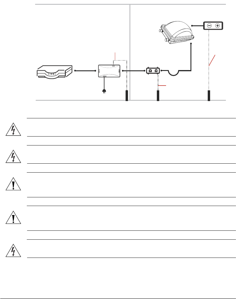
Become Familiar with the Installation Components
The ZoneFlex 7731 Wireless Bridge is designed for installation in an outdoor environment,
such as an exterior wall, or the roof overhang of a building, or a streetlight pole. Refer to
Figure 31 for the components involved in a typical installation.
Take note of the components that must be installed indoors and outdoors. The PoE injector
and power adapter that are shipped with the Wireless Bridge are for indoor use only.
Ruckus Wireless also strongly recommends that you form a drip loop on any cable that is
connected to devices that are installed outdoors (for example, the Wireless Bridge and
the Ethernet surge protector).
38
Physical Installation
Become Familiar with the Installation Components
Figure 31. Typical installation components using both PoE and DC power sources
Router or switch PoE injector
Cat5 Ethernet
cable
PoE power
adapter
Ground rod
Outdoor-rated
FTP cable
Drip loop
Outdoor-rated
FTP cable
Ground rod
ZoneFlex 7731
Outdoor
Wireless Bridge
DC power source
INDOORS OUTDOORS
DC cable
18 AWG min
green-and-
yellow
wire used
18 AWG min
green-and-yellow
wire used
Ground rod
Ethernet surge
protector
18 AWG min
green-and-
yellow
wire used
WARNING: Only trained and qualified personnel should be allowed to install, replace, or
service this equipment.
WARNING: Installation of this equipment must comply with local and national electrical
codes.
CAUTION: Make sure that you form a 3”-5” drip loop in any cable that will be placed
outdoors. This will prevent water from running along the cable and entering the Wireless
Bridge, the surge protector or the building where the cable terminates.
CAUTION: Be sure that grounding is available and that it meets local and national
electrical codes. For additional lightning protection, use lightning rods and lightning
arrestors.
.
WARNING: The Ruckus Wireless PoE injector (if supplied with your Wireless Bridge) is
for indoor use only. Never mount the PoE injector outdoors with the Wireless Bridge.
39
Physical Installation
Decide How You Will Supply Power to the Wireless Bridge
Decide How You Will Supply Power to the Wireless
Bridge
The Wireless Bridge supports Power over Ethernet (PoE) and 12 VC DC power and can be
connected to both power sources at the same time. If you connect the Wireless Bridge to
both PoE and DC power sources at the same time, it will use PoE as the primary power
source and DC power as the backup power source.
Deploying the Wireless Bridge
In this step, you will connect the Wireless Bridge to the network from its mounting location.
Step 1: Complete the Power Connections
Ruckus Wireless recommends using both PoE and DC power for backup in a typical
outdoor installation. For instructions on completing the power connection that you need
to make, refer to the procedures below:
■Use Power Over Ethernet
■Use DC Power
Use Power Over Ethernet
1. Take out the PoE injector and the power adapter from the Wireless Bridge package.
2. Obtain three Ethernet cables. Two of these Ethernet cables must be outdoor-rated.
3. Connect one end of the outdoor-rated Ethernet cable to the RJ45 port on the Wireless
Bridge, and then connect the other end to the Ethernet surge protector.
4. Connect one end of another Ethernet cable to another port on the Ethernet surge
protector, and then connect the other end to the AP/BRIDGE port on the PoE injector.
NOTE: Install the Ethernet surge protector between the Wireless Bridge and the PoE
injector and use two outdoor-rated Ethernet cables for the connections. See Figure 31 for
an example.
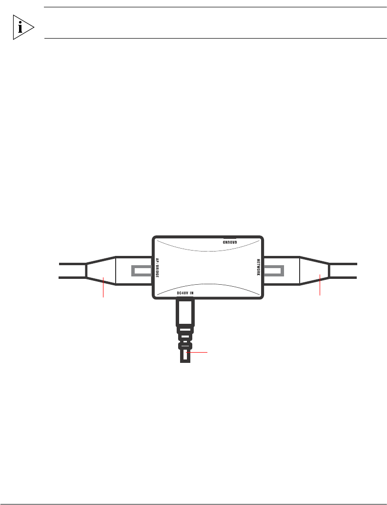
5. Connect one end of the other Ethernet cable to the NETWORK port on the PoE
injector, and then connect the other end to your network.
6. Connect the power jack to the DC 48V IN connector on the PoE injector.
WARNING: Do not apply power to the Wireless Bridge at this point. You should connect
the Wireless Bridge to a power source only after you finish connecting all other
components in “Step 3: Connect the Wireless Bridge to the Network” on page 44.
40
Physical Installation
Deploying the Wireless Bridge
Figure 32. Connect the Ethernet cables and power adapter to the PoE injector
To N etworkTo Outdoor Bridge
To AC Power Source
7. Take out one of the 20mm x 30mm sealing strips from the accessories bag.
8. Remove the adhesive backing from the sealing strip.
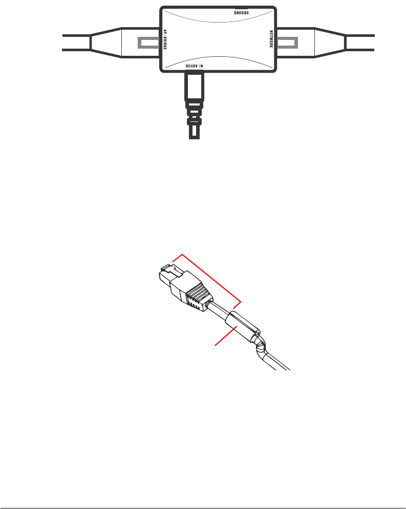
9. Wrap the sealing strip around the Ethernet cable, about 60mm from the Ethernet
connector.
Figure 33. Wrap the sealing strip around the Ethernet cable, 60mm from the Ethernet
connector
60mm
Sealing strip
10. Place the Ethernet cable in the cavity on the enclosure, and then press it into position.
Make sure the sealing strip protrudes beyond the entry and exit points.
11. Wrap the white P-clip cable clamp around the Ethernet cable, and then fasten it to the
Wireless Bridge chassis using one of the short machine screws supplied.
41
Physical Installation
Deploying the Wireless Bridge
Figure 34. Install the white P-clip clamp
Sealing
strip
P-clip cable
clamp
You have completed setting up the PoE power connection.
Use DC Power
To use DC to power the Wireless Bridge, you need to connect a DC cable (not supplied
with the Wireless Bridge) to the DC terminal block.
1. Take out the DC terminal block from the small plastic bag that contains the bottom
cover of the Wireless Bridge.
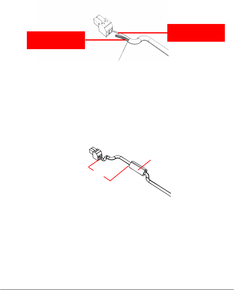
2. Connect the DC cable’s ground wire to V- terminal. If you are looking at the terminal
block with the wiring terminal screws on top, the V- terminal is on the left side.
3. Connect the DC cable’s +12V DC wire to the V+ terminal. If you are looking at the
terminal block with the wiring terminal screws on top, the V+ terminal is on the right
side.
42
Physical Installation
Deploying the Wireless Bridge
Figure 35. Connect the ground wire to the V- terminal and the +12V DC wire to the V+
terminal
Ground Wire to
V- Terminal
12V DC Wire to
V+ Terminal
4. Using a 3mm Phillips screw, tighten the wiring terminal screws. Screw torque value must
be 20.5 mN-m ± 2 mN-m.
5. Take out one of the 20mm x 30mm sealing strips from the accessories bag.
6. Remove the adhesive backing from the sealing strip.
7. Wrap the sealing strip around the DC cable, about 60mm from the DC terminal block.
Figure 36. Wrap the sealing strip around the DC cable, 60mm from the DC terminal
block
60mm
Sealing strip
8. Connect the DC terminal block to the 12V DC port on the Wireless Bridge.
9. Place the DC cable into the right cable groove on the enclosure, and then press it into
position. Make sure the sealing strip protrudes beyond the entry and exit points.
10. Wrap the white P-clip cable clamp around the DC cable, and then fasten it to the
Wireless Bridge chassis using one of the short machine screws supplied with the
Wireless Bridge.