Senao Networks ZF7731 Zone Flex 7731 802.11n Industrial Point to Point Bridge User Manual Bali GSG
Senao Networks, Inc. Zone Flex 7731 802.11n Industrial Point to Point Bridge Bali GSG
Contents
MANUAL 2
43
Physical Installation
Deploying the Wireless Bridge
WARNING: Do not apply power to the Wireless Bridge at this point. You should connect
the Wireless Bridge to a power source only after you finish connecting all other
components in “Step 3: Connect the Wireless Bridge to the Network” on page 44.
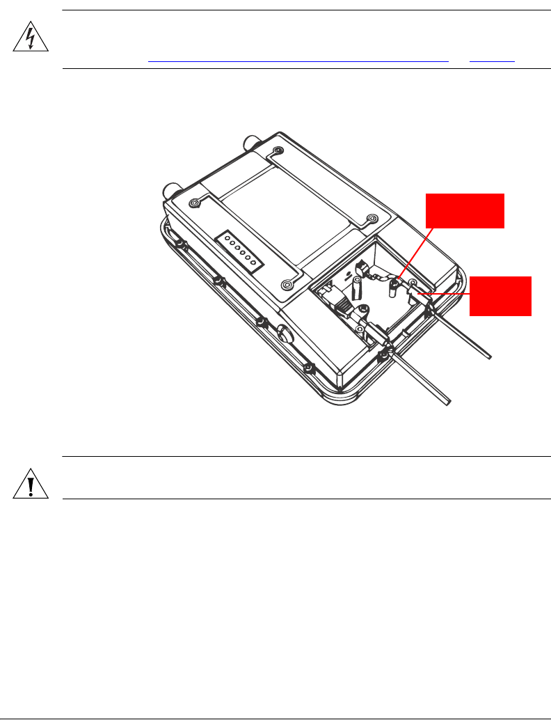
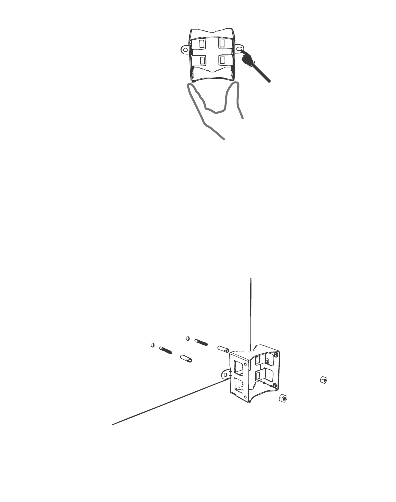
Figure 37. Install the white P-clip cable clamp
P-clip Cable
Clamp
Sealing
Strip
CAUTION: If you are not connecting the DC cable to the DC terminal block, make sure
you cover the right cable groove with the supplied sealing plug.
You have completed setting up the DC power connection.
44
Physical Installation
Deploying the Wireless Bridge
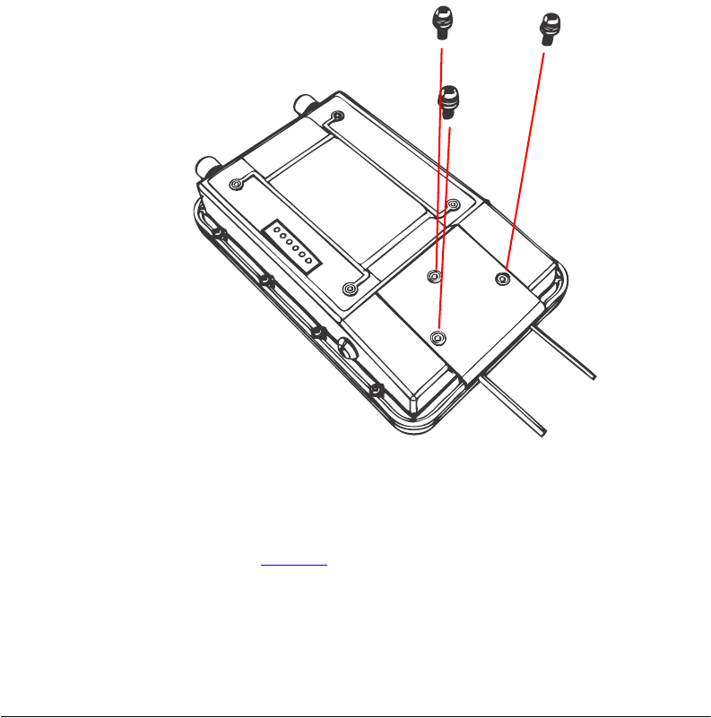
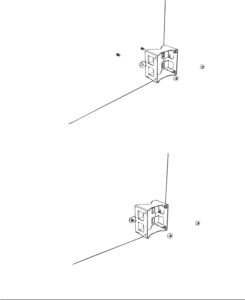
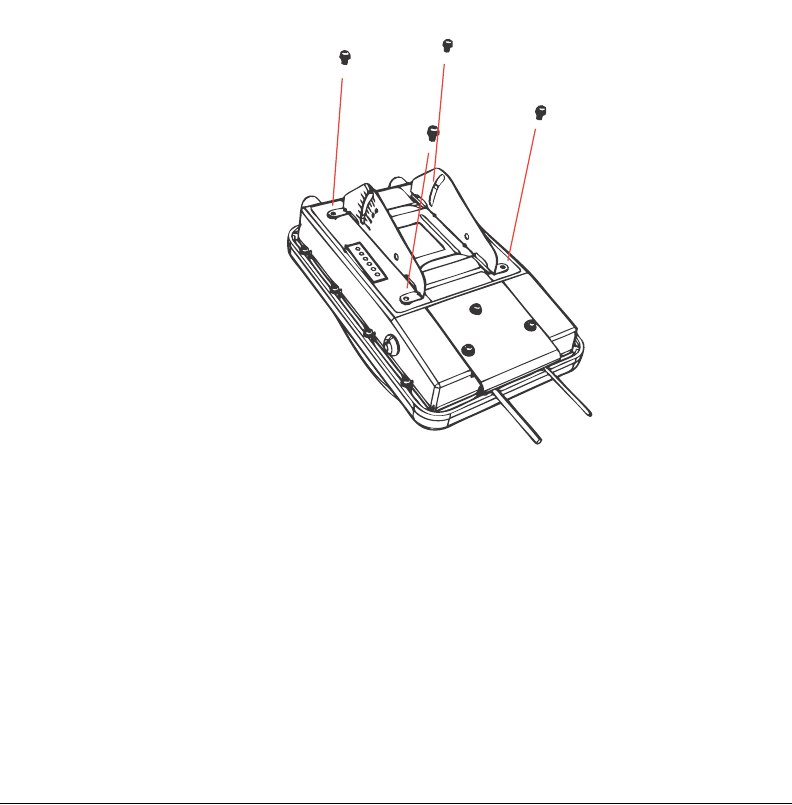
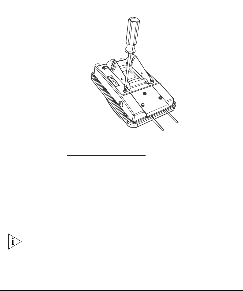
Step 2: Install the Back Panel Cover
1. Make sure that the perimeter rubber gasket on the underside of the bottom cover is
in place and is clear of debris.
2. Place the bottom cover of the Wireless Bridge onto the bottom section.
3. Using the three gasketed machine screws that are supplied with the Wireless Bridge,
fasten the bottom cover to the chassis. Screw torque value must be 6.9 ± 0.2 kgf-cm
(6.2 ± 0.2 lbfin) to obtain a proper seal.
Figure 38. Fasten the bottom cover using three machine screws
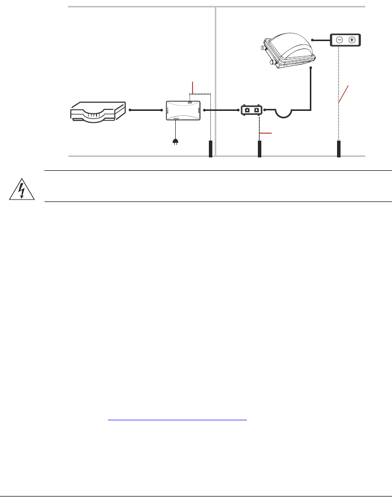
Step 3: Connect the Wireless Bridge to the Network
In this step, you will connect the Wireless Bridge from its mounting location to the
network. Follow the steps below for a typical installation that uses both PoE and DC
power as power sources. Figure 39 shows an example of the connections required for a
typical installation that uses both PoE and DC power.
45
Physical Installation
Deploying the Wireless Bridge
Figure 39. Typical installation components using both PoE and DC power sources
Router or switch PoE injector
Cat5 Ethernet
cable
PoE power
adapter
Ground rod
Outdoor-rated
FTP cable
Drip loop
Outdoor-rated
FTP cable
Ground rod
ZoneFlex 7731
Outdoor
Wireless Bridge
DC power source
INDOORS OUTDOORS
DC cable
18 AWG min
green-and-
yellow
wire used
18 AWG min
green-and-yellow
wire used
Ground rod
Ethernet surge
protector
18 AWG min
green-and-
yellow
wire used
WARNING: Do not apply power to the Wireless Bridge until you finish connecting all
other components.
1. Take the root bridge to its mounting location.
2. Verify that the Cat5e FTP cable (outdoor-rated) from the Wireless Bridge is long enough
to reach the PoE injector that is installed indoors.
3. Create a drip loop in any cable installed outdoors. This will prevent water from running
along the cable and entering the Wireless Bridge or the building where the cable
terminates.
4. Verify that the RJ45 port on the Wireless Bridge is connected to the AP/BRIDGE port
on the PoE injector.
5. Connect the Ethernet cable from the NETWORK port on the PoE injector to your
network router or switch.
6. Apply power to the Wireless Bridge.
• If you are using PoE, plug the power adapter in to an AC power source.
• If you are using DC power, connect the DC cable to a DC power source.
7. Verify that the PWR LED on the back of the Wireless Bridge is steady green.
8. Repeat steps 1-7 for the non-root bridge.
9. Continue to “Attaching the Mounting Brackets”.
46
Physical Installation
Attaching the Mounting Brackets
Attaching the Mounting Brackets
What You Will Need
To complete this procedure, you will need the following items:
■Static bracket
■Dynamic bracket
■Wall anchors
■Flat washers
■Hex nuts
■10mm ratchet wrench
If you are mounting the Wireless Bridge on a flat surface, you will also need an electric drill
with an 8mm drill bit.
If you are mounting the Wireless Bridge on a pipe or pole, you will also need the following:
■A 30mm to 60 mm (1.18 in. to 2.36 in.) pipe or pole
■Steel clamp
■10mm flathead screwdriver
Step 1: Attach the Static Bracket to the Mounting Surface
The procedure for attaching the bracket to the mounting surface depends on whether you
are mounting the Wireless Bridge to a flat surface or a pole.
■Attaching the Bracket to a Flat Surface
■Attaching the Bracket to a Pole
Attaching the Bracket to a Flat Surface
WARNING: Ruckus Wireless strongly recommends that you wear eye protection before
drilling holes on the mounting surface.
NOTE: The wall anchors that are supplied with the Wireless Bridge are for mounting on
solid masonry walls only. If you are mounting the Wireless Bridge on other materials (for
example, drywall, wood, or hollow cinder block), you will need the appropriate types of
wall anchors. Check your local hardware store for options.
1. Place the static bracket at the exact location on the mounting surface where you want
to mount it.
2. Use the static bracket as a template to mark the locations of the mounting holes on
the two mounting tabs.
47
Physical Installation
Attaching the Mounting Brackets
Figure 40. Mark the locations of the mounting holes
3. Remove the static bracket from the mounting surface.
4. Drill an 8mm-diameter hole with a depth of 36mm-38mm into each of the markings
that you made on the mounting surface.
5. Insert a wall anchor (with the unthreaded part first) into each of the holes that you
drilled.
6. Place a metal cone on each wall anchor, and then place a flat washer on top of the
metal cone.
Figure 41. Insert a wall anchor into each hole that you drilled, and then place a metal
cone and a flat washer on top
48
Physical Installation
Attaching the Mounting Brackets
7. Align the two screw holes on the bracket with the wall anchors that you inserted earlier.
Figure 42. Align the screw holes on the bracket with the wall anchors
8. Use two hex nuts to attach the bracket to the mounting surface.
Figure 43. Use two hex nuts to attach the bracket to the surface
49
Physical Installation
Attaching the Mounting Brackets
9. Using a 10mm open-end wrench, tighten the nuts to secure the bracket to the
mounting surface. Screw torque value must be 4kg-5kg. As you tighten the nuts, the
metal cones that are built into the wall anchors will expand and lock the wall anchors
into place.
10. Continue to “Step 2: Attach the Dynamic Bracket to the Wireless Bridge”.
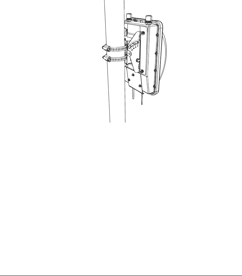
Attaching the Bracket to a Pole
The Wireless Bridge can be mounted vertically on a 30mm to 60mm (1.18 in. to 2.36 in.)
pole.
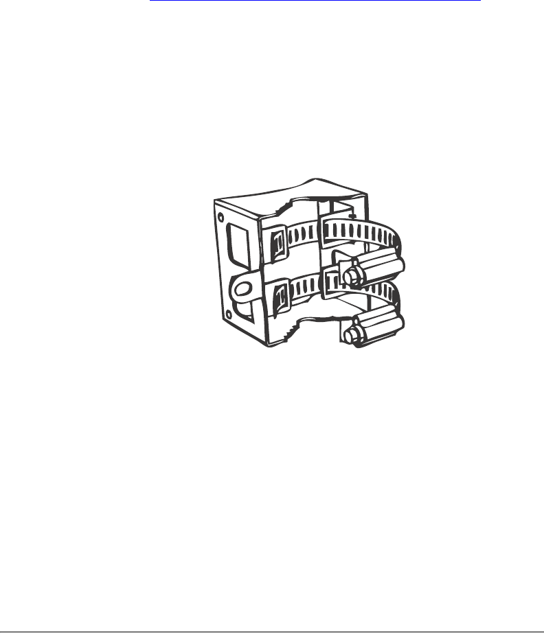
1. Insert the open end of the steel clamps into the two tabs on the bracket.
Figure 44. Insert the steel clamps into the two tabs on the bracket
50
Physical Installation
Attaching the Mounting Brackets
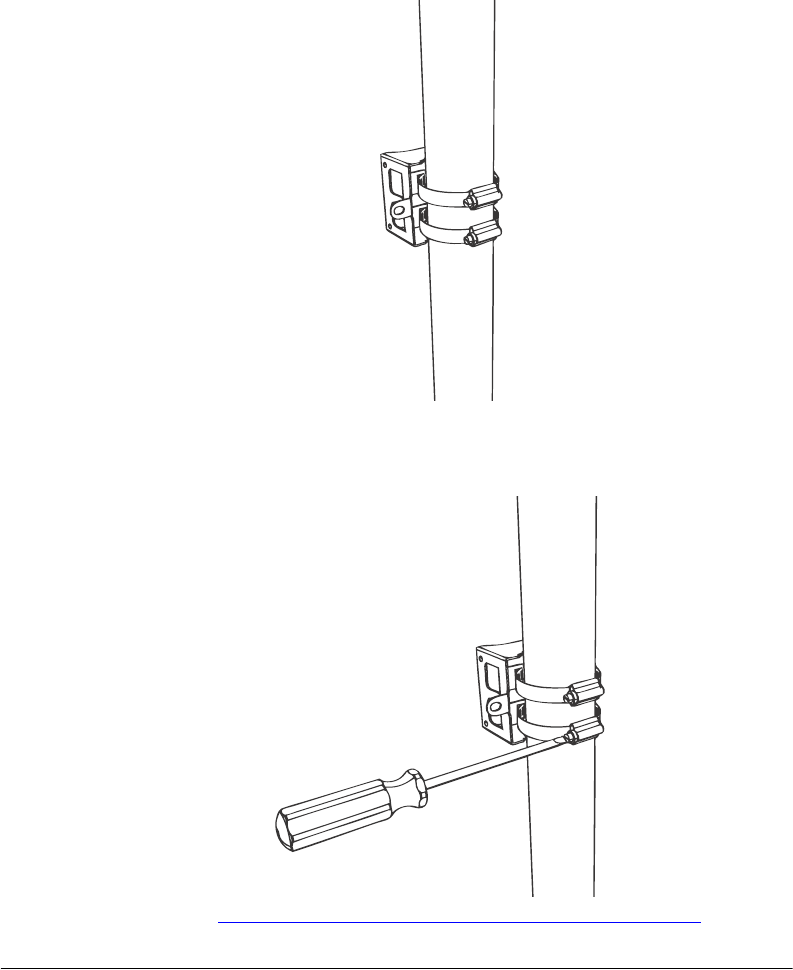
2. Use the clamps to attach the bracket to the pole.
Figure 45. Use the clamps to attach the bracket to the pole
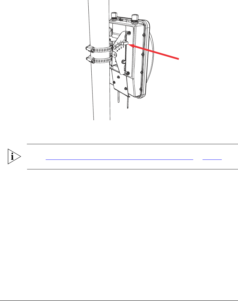
3. Using a 10mm flathead screwdriver, tighten the clamp locks to secure the bracket to
the pole. Screw torque value must be 1.1 N-m ± 0.1 N-m.
Figure 46. Tighten the clamp locks to secure the bracket
4. Continue to “Step 2: Attach the Dynamic Bracket to the Wireless Bridge”.
51
Physical Installation
Attaching the Mounting Brackets
Step 2: Attach the Dynamic Bracket to the Wireless Bridge
1. Place the dynamic bracket onto the flat side of the Wireless Bridge so that the four
screw holes on the bracket align with the four screw holes on the Wireless Bridge. Make
sure that the shorter end of the mounting bracket is on the same side as the antenna
connector.
2. Insert four machine screws (supplied with mounting kit) into the screw holes on the
bracket.
Figure 47. Insert four machines screws into the screw holes
52
Physical Installation
Mounting the Wireless Bridge
3. Using a 6mm Phillips screwdriver, tighten the four machine screws to fasten the bracket
to the Wireless Bridge. Screw torque value must be 0.4 N-m ± 0.1 N-m.
Figure 48. Fasten bracket to the Wireless Bridge
4. Continue to “Mounting the Wireless Bridge” in the next section.
Mounting the Wireless Bridge
To mount the Wireless Bridge, you will need to join the two mounting brackets that you
attached earlier to the device and the mounting surface. For this procedure, you will need
the following items:
■Hex bolts
■Thumb screws
■10mm ratchet wrench
NOTE: Figures in this section show mounting on a vertical pole. Procedures for mounting
on a flat surface are similar.
To join the two mounting brackets together:
1. Join the two brackets as shown in Figure 49. Make sure that:
53
Physical Installation
Mounting the Wireless Bridge
• The dynamic bracket (attached to the Wireless Bridge) encloses the static bracket
(attached to the mounting surface).
•(For mounting on a vertical pole) The side of the Wireless Bridge with the antenna
connectors is at the top, especially if you are planning to install external antennas.
Figure 49. Joining the two brackets in a vertical pole installation
2. Align the mounting holes on the dynamic bracket with the mounting holes on the static
bracket.
3. Place a split lock washer, and then a flat washer onto a hex bolt. Then insert the hex
bolt into one of the lower mounting holes.

54
Physical Installation
Mounting the Wireless Bridge
Figure 50. Insert hex bolts into lower mounting holes
NOTE: Make sure the screw-washer assembly is in correct order. The split-lock washer
should be in the middle and the flat washer should touch the bracket.
4. Repeat Step 3 for the lower mounting hole on the other side.
5. Finger tighten the hex bolts.
6. Insert the two thumb screws into the upper mounting holes as shown in Figure 51.
55
Physical Installation
Mounting the Wireless Bridge
Figure 51. Insert thumb screws into the upper mounting holes
7. Finger tighten the thumb screws.
8. Adjust the Wireless Bridge to your desired orientation.
NOTE: If you have not yet determined the optimal orientation for your Wireless Bridge,
refer to “Determine the Optimal Mounting Location and Orientation” on page 36 for
orientation guidelines.
9. Using a 10mm ratchet wrench, tighten the hex bolts to fix the Wireless Bridge’s
orientation. Screw torque value must be 0.7 N-m ± 0.1 N-m.
You have completed mounting the root bridge. Perform the same procedure for mounting
the non-root bridge.
56
Physical Installation
Mounting and Connecting the External Antenna (Optional)
Mounting and Connecting the External Antenna
(Optional)
If you want to extend the range of your wireless bridge connection, you can connect an
external patch antenna to the standard N-type female connectors on the Wireless Bridge.
WARNING: Only trained and qualified personnel should be allowed to install, replace,
or service this equipment.
WARNING: Before connecting the antenna to the Wireless Bridge, make sure that you
disconnect the Wireless Bridge from the power source.
1. Disconnect the Wireless Bridge from the power source.
2. Unscrew the metal caps that protect the antenna connectors. Place the metal caps in
a safe place, in case you need them later.
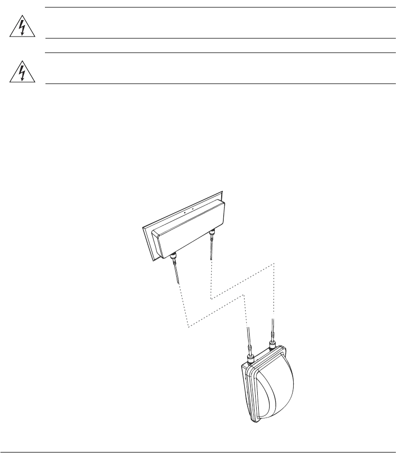
3. Connect the antenna to the standard N-type female antenna connectors.
Figure 52. Connect the external antenna to the standard N-type female connectors on
the Wireless Bridge.

57
Aiming the Bridge Pair
Mounting and Connecting the External Antenna (Optional)
4. Ensure that antenna connectors are firmly tightened, and apply weatherproofing tape
to the antenna connectors to help prevent water from entering the connectors.
5. Reconnect the Wireless Bridge to the power source.
CAUTION: If you are not connecting external antennas to the Wireless Bridge, make sure
that the metal caps remain installed and securely fastened to protect the interface from
elements, such as water or dirt.
You have completed connecting the external antenna to the Wireless Bridge.
7Aiming the Bridge Pair
Once both units are installed in their permanent locations, press the Aiming Button on
the outside of either unit to begin aiming. Alternatively, you can start the aiming process
via the Web browser, by clicking Start Aiming on the Status > Wireless page.
1. Press the blue button on the side of either bridge and hold it for 4 seconds.
• The bottom LED turns yellow, indicating that the unit is in Aiming Mode.
• If the unit is in Aiming mode but there is no association between the two bridge
units, all LEDs will cycle yellow until the two ZoneFlex 7731 units have associated.
2. Adjust the azimuth and elevation of the first unit to maximize the Aiming LED indica-
tors. RSSI (received signal strength indication) values are shown in Ta ble 6.
Table 6. RSSI values of LED indicators
LED Status RSSI (<=)
LED 6 Solid 35 (Max)
Flashing 30
LED 5 Solid 28
Flashing 25
LED 4 Solid 23
Flashing 20
LED 3 Solid 18
Flashing 15
LED 2 Solid 13
Flashing 10
LED 1 Solid 8
Flashing 5 (Min)
58
Aiming the Bridge Pair
Mounting and Connecting the External Antenna (Optional)
3. After one unit is at its maximum link level, adjust the second unit to increase the link
performance.
4. If the unit's elevation adjustment needs to be reversed, remove the 4 bolts mating the
two mounting bracket pieces together. Remove the 4 mounting screws attaching the
bracket to the ZoneFlex 7731 enclosure, rotate the bracket 180º and reattach the
bracket to the enclosure. Repeat steps 2 through 7. Adjust the ZoneFlex 7731 to your
desired orientation.
NOTE: The cable end of the ZoneFlex 7731 should always be pointing down.
5. Once the ZoneFlex 7731 is in the proper orientation, tighten the thumb screws flush
to the bracket.
6. Using a 10mm ratchet wrench, tighten the two hex bolts to fix the unit's orientation.
The bolt torque value must be 0.6-0.8 Newton meter (Nm).
7. Verify that the ZoneFlex 7731 link performance has not changed.
8. Press the blue Aiming button once again to stop aiming.
9. Repeat steps 1-8 for the other bridge unit.
NOTE: If the unit is mounted in a position that does not allow the user to view the LEDs,
the Web UI can be used for Aiming. On the Status > Wireless page, pressing the “Start
Aiming” link is the same as pressing the blue Aiming button. The Signal Strength is shown
on the Web page. More green bars indicate higher signal strength.
10. If using the Web interface for aiming, adjust the orientation of the units to maximize
the green bars under “Signal Strength.”
11. For more precise aiming, the value under “ACK RSSI” can also be used. A higher ACK
RSSI indicates better signal strength. Both the green bars in the Web interface and the
LEDs on the outside of the bridge units serve as indicators of ACK RSSI values.
NOTE: For best results, it is important to perform the aiming procedure for both units.
59
Verifying the Connection
Mounting and Connecting the External Antenna (Optional)
8Verifying the Connection
Once you have completed the hardware installation and aiming procedure for both
Wireless Bridges, verify the connection and signal integrity between the bridge pair using
the following procedure:
1. Access the root bridge Web interface by entering its IP address into a Web browser
on a computer connected to the same switch that the root bridge is connected to.
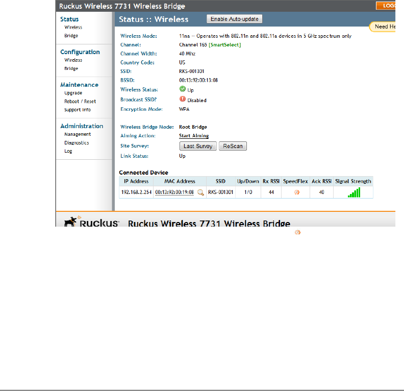
2. On the Status > Wireless page, check to make sure the non-root bridge is listed under
the Connected Device section.
Figure 53. Viewing connected device from the Web interface
3. On the Status > Wireless page, click the SpeedFlex icon to launch the SpeedFlex
Wireless Performance Test.
4. Click Start to begin testing
5. Once the test is completed, the following result page is displayed.

60
What to Do Next
Change the Administrative Password
Figure 54. SpeedFlex Performance Test succeeded
9What to Do Next
The following are some of the post-installation tasks that Ruckus Wireless recommends.
Refer to the ZoneFlex 7731 802.11n Point to Point Bridge User Guide for more information
on configuring and managing the Wireless Bridge.
Change the Administrative Password
Management access to the Web interface of the Wireless Bridge is controlled through
administrative user name and password. As soon as you complete the Wireless Bridge
setup, make sure you log on to the Wireless Bridge’s Web interface and change the default
administrative user name and password. This will help prevent unauthorized users from
logging in to the Wireless Bridge’s Web interface and changing the Wireless Bridge
settings to compromise your network.
Using FlexMaster to Manage the Wireless Bridge
If you are planning to use Ruckus Wireless FlexMaster to manage the ZoneFlex 7731, this
guide describes the required steps that will enable the Wireless Bridge to report to and
communicate with FlexMaster successfully.
(Optional) Set the FlexMaster Server Address
If you have a FlexMaster server installed on the network and you intend to use FlexMaster
to manage the Wireless Bridge, you can set the FlexMaster server address at this point.
Before starting this procedure, make sure you obtain the correct FlexMaster server URL.

61
What to Do Next
Using FlexMaster to Manage the Wireless Bridge
NOTE: In addition to setting the FlexMaster server URL manually on the Wireless Bridge,
you can also use DHCP Option 43 or DNS to point the Wireless Bridge to the FlexMaster
server. For more information, refer to the FlexMaster User Guide.
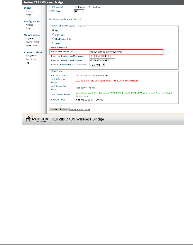
1. On the menu, click Administration > Management.
2. Scroll down the page to the TR069 / SNMP Management Choice section.
3. Verify that the Auto option is selected.
4. In FlexMaster Server URL, type the URL of the FlexMaster server on the network. You
can use either http or https to connect to the URL and include either the host name
or IP address of the FlexMaster server in the URL. The following are examples of valid
FlexMaster server URLs:
http://flexmaster/intune/server
https://flexmaster/intune/server
http://192.168.20.1/intune/server
https://192.168.20.1/intune/server
5. Click Update Settings to save your changes.
You have completed setting the FlexMaster server address on the Wireless Bridge.
62
What to Do Next
Read Related Documentation
Figure 55. Type the FlexMaster server URL
Read Related Documentation
If you are using FlexMaster to manage the Wireless Bridge, make sure you read the
accompanying documentation to learn how to configure and manage the Wireless Bridge
from the FlexMaster Web interface.
The latest versions of Ruckus Wireless product documentation are available for download
on the Ruckus Wireless Support Web site at:
http://support.ruckuswireless.com/documents

Professional Installation Instruction
1. Installation personal: This product is designed for specific application and needs to be installed by a qualified personal who has RF and related rule knowledge. The
general user shall not attempt to install or change the setting.
2. Installation location: The product shall be installed at a location where the radiating antenna can be kept 20 cm from nearby person in normal operation condition to meet
regulatory RF exposure requirement. Additionally, installation locations with 35km of Terminal Doppler Weather Radar locations shall follow instructions below.
3. External antenna: Use only the antennas which have been approved by Ruckus Wireless. The non-approved antenna(s) may produce unwanted spurious or excessive
RF transmitting power which may lead to the violation of FCC limit and is prohibited.
4. Installation procedure: Please refer to user’s manual for the detail.
5. Warning: Please carefully select the installation position and make sure that the final output power does not exceed the limit set force in US Rule CFR 47 part 15 section
6. 15.247 & 15.407. The violation of the rule could lead to serious federal penalty.
Terminal Doppler Weather Radar Interference
Any installation of this product within 35km of a Terminal Doppler Weather Radar (TDWR) location must be separated by at least 30MHz (center-to-center) from the TDWR
operating frequency. A database of TDWR locations and their center frequencies can be found at the following URL: http://www.spectrumbridge.com/udia/home.aspx.
The installer is encouraged to register installations in the 5470-5725 frequency band at the same URL, where registration instructions are provided.
Federal Communications Commission Notices
This product complies with Part 15 of the FCC Rules. Operation is subject to the following two conditions: (1) this device may not cause harmful interference, and (2) this
device must accept any interference received, including interference that may cause undesired operation.
Radiation Exposure Statement
This equipment complies with FCC radiation exposure limits set forth for an uncontrolled environment. This equipment should be installed and operated with minimum
distance 20cm between the radiator and your body. This equipment shall not be colocated with any other transmitter.
Harmful Interference Notice
This product has been tested and complies with the specifications for a Class B digital device, pursuant to Part 15 of the FCC Rules. These limits are designed to provide
reasonable protection against harmful interference in a residential installation. This equipment generates, uses, and can radiate radio frequency energy and, if not installed
and used according to the instructions, may cause harmful interference to radio communications. However, there is no guarantee that interference will not occur in a
particular installation. If this equipment does cause harmful interference to radio or television reception, which is found by turning the equipment off and on, the user is
encouraged to try to correct the interference by one or more of the following measures:
Reorient or relocate the receiving antenna
Increase the separation between the equipment or devices
Connect the equipment to an outlet other than the receiver's
Consult a dealer or an experienced radio/TV technician for assistance
Changes or modifications to this equipment that have not been approved by Ruckus Wireless may void the user's authority to operate this equipment.
For operation within 5.15 – 5.25GHz frequency range, it is restricted to indoor environment.
External Antenna
This device has been designed to operate with a patch antenna, and having a maximum gain of 23 dBi. Other antenna types or having a gain greater than 23 dBi are
strictly prohibited for use with this device. The required antenna impedance is 50 ohms.
Industry Canada Statement
This device complies with Industry Canada ICES-003 and RSS210 rules. Operation is subject to the following two conditions:
1. This device may not cause interference and
2. This device must accept any interference, including interference that may cause undesired operation of the device.
Cet appareil est conforme aux normes NMB003 et RSS210 d'Industrie Canada. Le fonctionnement est soumis aux conditions suivantes :
1. Ce périphérique ne doit pas causer d'interférences;
2. Ce périphérique doit accepter toutes les interférences reçues, y compris celles qui risquent d'entraîner un fonctionnement indésirable.
This equipment complies with IC radiation exposure limits set forth for an uncontrolled environment. This equipment should be installed and operated with minimum
distance 20cm between the radiator & your body.
Caution:
The device for the band 5150-5250 MHz is only for indoor usage to reduce potential for harmful interference to co-channel mobile satellite systems. High power radars are
allocated as primary users (meaning they have priority) of 5250-5350 MHz and 5650-5850 MHz and these radars could cause interference and/or damage to LE-LAN
devices.
This device has been designed to operate with an antenna having a maximum gain of 23 dBm. Antenna having a higher gain is strictly prohibited per regulations of Industry
Canada. The required antenna impedance is 50 ohms.
Australia Statement
This device complies with the ACMA requirements for a Wi-Fi device namely Radio Communications (Low Impact Potential Devices) Class Licence 2000 Amd. 1:2007 and
Radiocommunications (Compliance Labelling – Electromagnetic Radiation) Notice 2003. The equipment complies with the ACMA requirements for radiation exposure for a
"general user/non-aware user". This equipment should be installed and operated with a minimum distance of 50 cm between the radiator and your body. This equipment
complies with the Australian safety requirements if connected to an approved power supply. The frequency band 5150 – 5350 MHz is restricted to indoor use.
European Union Notices
This product only supplied by Limited Power sources (sub-clause 2.5 of standard EN 60950-1).
Compliance Information for 5-GHz Wireless Products
The following standards were applied during the assessment of the product against the requirements of the Directive 1999/5/EC:
EN 301 893
EMC: EN 301 489-1, EN 301 489-17
Safety: EN 60950, EN 50385
The frequency band 5150 – 5350 MHz is restricted to indoor use.
National Restrictions
This product may be used in all EU countries (and other countries following the EU directive 1999/5/EC) without any limitation except for the countries mentioned below:
Ce produit peut être utilisé dans tous les pays de l’UE (et dans tous les pays ayant transposés la directive 1999/5/CE) sans aucune limitation, excepté pour les pays
mentionnés ci-dessous:
Questo prodotto è utilizzabile in tutte i paesi EU (ed in tutti gli altri paesi che seguono le direttive EU 1999/5/EC) senza nessuna limitazione, eccetto per i paesii menzionati
di seguito:
Das Produkt kann in allen EU Staaten ohne Einschränkungen eingesetzt werden (sowie in anderen Staaten die der EU Direktive 1999/5/CE folgen) mit Außnahme der
folgenden aufgeführten Staaten:
Belgium
The Belgian Institute for Postal Services and Telecommunications (BIPT) must be notified of any outdoor wireless link having a range exceeding 300 meters. Please check
http://www.bipt.be for more details.

Draadloze verbindingen voor buitengebruik en met een reikwijdte van meer dan 300 meter dienen aangemeld te worden bij het Belgisch Instituut voor postdiensten en
telecommunicatie (BIPT). Zie http://www.bipt.be voor meer gegevens.
Les liaisons sans fil pour une utilisation en extérieur d’une distance supérieure à 300 mètres doivent être notifiées à l’Institut Belge des services Postaux et des
Télécommunications (IBPT). Visitez http://www.ibpt.be pour de plus amples détails.
Taiwan Statement
This device has been designed to operate with a patch antenna, and having a maximum gain of 23 dBi, such as the ARC-ID5823B88 Other antenna types or having a gain
greater than 23 dBi are strictly prohibited for use with this device. The required antenna impedance is 50 ohms.
Turkey Statement
Operation in the 5,475-5,725 Ghz band is not allowed.
Česky
[Czech]
Ruckus Wireless tímto prohlašuje, že tento Radio LAN je ve shodě se základními požadavky a dalšími příslušnými
ustanoveními směrnice 1999/5/ES.
Dansk
[Danish]
Undertegnede Ruckus Wireless erklærer herved, at følgende udstyr Radio LAN overholder de væsentlige krav og øvrige
relevante krav i direktiv 1999/5/EF.
Deutsch
[German]
Hiermit erklärt Ruckus Wireless, dass sich das Gerät Radio LAN in Übereinstimmung mit den grundlegenden
Anforderungen und den übrigen einschlägigen Bestimmungen der Richtlinie 1999/5/EG befindet.
Eesti
[Estonian]
Käesolevaga kinnitab Ruckus Wireless seadme Radio LAN vastavust direktiivi 1999/5/EÜ põhinõuetele ja nimetatud
direktiivist tulenevatele teistele asjakohastele sätetele.
English Hereby, Ruckus Wireless declares that this Radio LAN is in compliance with the essential requirements and other
relevant provisions of Directive 1999/5/EC.
Español
[Spanish]
Por medio de la presente Ruckus Wireless declara que el Radio LAN cumple con los requisitos esenciales y cualesquiera
otras disposiciones aplicables o exigibles de la Directiva 1999/5/CE.
Ελληνική
[Greek]
ΜΕ ΤΗΝ ΠΑΡΟΥΣΑ Ruckus Wireless ∆ΗΛΩΝΕΙ ΟΤΙ Radio LAN ΣΥΜΜΟΡΦΩΝΕΤΑΙ ΠΡΟΣ ΤΙΣ ΟΥΣΙΩ∆ΕΙΣ
ΑΠΑΙΤΗΣΕΙΣ ΚΑΙ ΤΙΣ ΛΟΙΠΕΣ ΣΧΕΤΙΚΕΣ ∆ΙΑΤΑΞΕΙΣ ΤΗΣ Ο∆ΗΓΙΑΣ 1999/5/ΕΚ.
Français
[French]
Par la présente Ruckus Wireless déclare que l'appareil Radio LAN est conforme aux exigences essentielles et aux autres
dispositions pertinentes de la directive 1999/5/CE.
Italiano
[Italian]
Con la presente Ruckus Wireless dichiara che questo Radio LAN è conforme ai requisiti essenziali ed alle altre
disposizioni pertinenti stabilite dalla direttiva 1999/5/CE.
Latviski
[Latvian]
Ar šo Ruckus Wireless deklarē, ka Radio LAN atbilst Direktīvas 1999/5/EK būtiskajām prasībām un citiem ar to
saistītajiem noteikumiem.
Lietuvių
[Lithuanian]
Šiuo Ruckus Wireless deklaruoja, kad šis Radio LAN atitinka esminius reikalavimus ir kitas 1999/5/EB Direktyvos
nuostatas.
Nederlands
[Dutch]
Hierbij verklaart Ruckus Wireless dat het toestel Radio LAN in overeenstemming is met de essentiële eisen en de andere
relevante bepalingen van richtlijn 1999/5/EG.
Malti
[Maltese]
Hawnhekk, Ruckus Wireless, jiddikjara li dan Radio LAN jikkonforma mal-ħtiġijiet essenzjali u ma provvedimenti oħrajn
relevanti li hemm fid-Dirrettiva 1999/5/EC.
Magyar
[Hungarian]
Alulírott, Ruckus Wireless nyilatkozom, hogy a Radio LAN megfelel a vonatkozó alapvetõ követelményeknek és az
1999/5/EC irányelv egyéb elõírásainak.
Polski
[Polish]
Niniejszym Ruckus Wireless oświadcza, że Radio LAN jest zgodny z zasadniczymi wymogami oraz pozostałymi
stosownymi postanowieniami Dyrektywy 1999/5/EC.
Português
[Portuguese]
Ruckus Wireless declara que este Radio LAN está conforme com os requisitos essenciais e outras disposições da
Directiva 1999/5/CE.
Slovensko
[Slovenian]
Ruckus Wireless izjavlja, da je ta Radio LAN v skladu z bistvenimi zahtevami in ostalimi relevantnimi določili direktive
1999/5/ES.
Slovensky
[Slovak]
Ruckus Wireless týmto vyhlasuje, že Radio LAN spĺňa základné požiadavky a všetky príslušné ustanovenia Smernice
1999/5/ES.
Suomi
[Finnish]
Ruckus Wireless vakuuttaa täten että Radio LAN tyyppinen laite on direktiivin 1999/5/EY oleellisten vaatimusten ja sitä
koskevien direktiivin muiden ehtojen mukainen.
Svenska
[Swedish]
Härmed intygar Ruckus Wireless att denna Radio LAN står I överensstämmelse med de väsentliga egenskapskrav och
övriga relevanta bestämmelser som framgår av direktiv 1999/5/EG.
Íslenska
[Icelandic]
Hér með lýsir Ruckus Wireless yfir því að Radio LAN er í samræmi við grunnkröfur og aðrar kröfur, sem gerðar eru í
tilskipun 1999/5/EC.
Norsk
[Norwegian]
Ruckus Wireless erklærer herved at utstyret Radio LAN er i samsvar med de grunnleggende krav og øvrige relevante
krav i direktiv 1999/5/EF.
800-70238-001-A