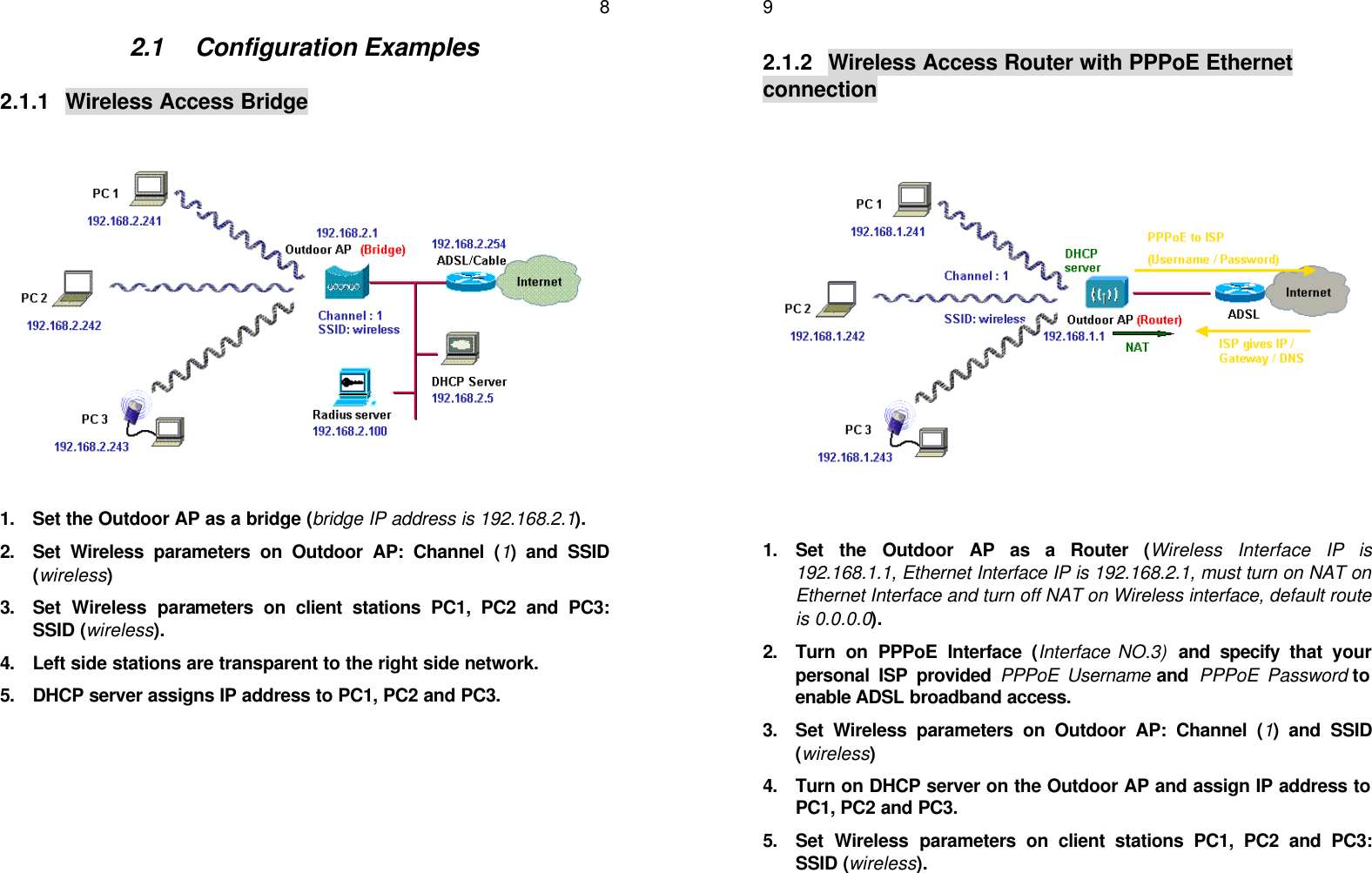
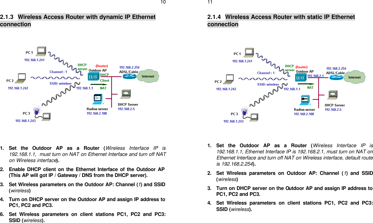
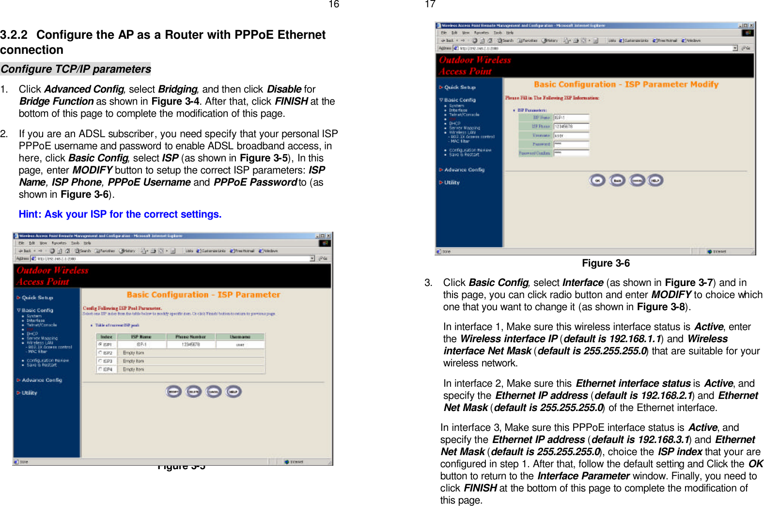
SendFar Technology OAP-04003 Wireless Access Point User Manual AP814 rev
SendFar Technology Co., Ltd. Wireless Access Point AP814 rev
UserManual.wiki
>
SendFar Technology
>
OAP-04003 User Manual
>
Users Manual Revised
Contents
1.
DoC
2.
Users Manual Revised
Users Manual Revised
Navigation menu
Upload a User Manual
Namespaces
Wiki Guide
HTML
PDF
Info
Views
User Manual
Discussion / Help
Navigation
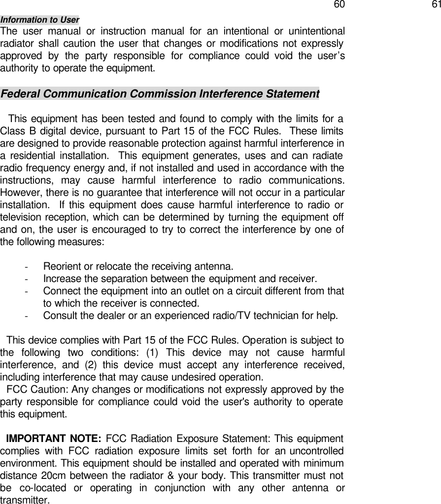
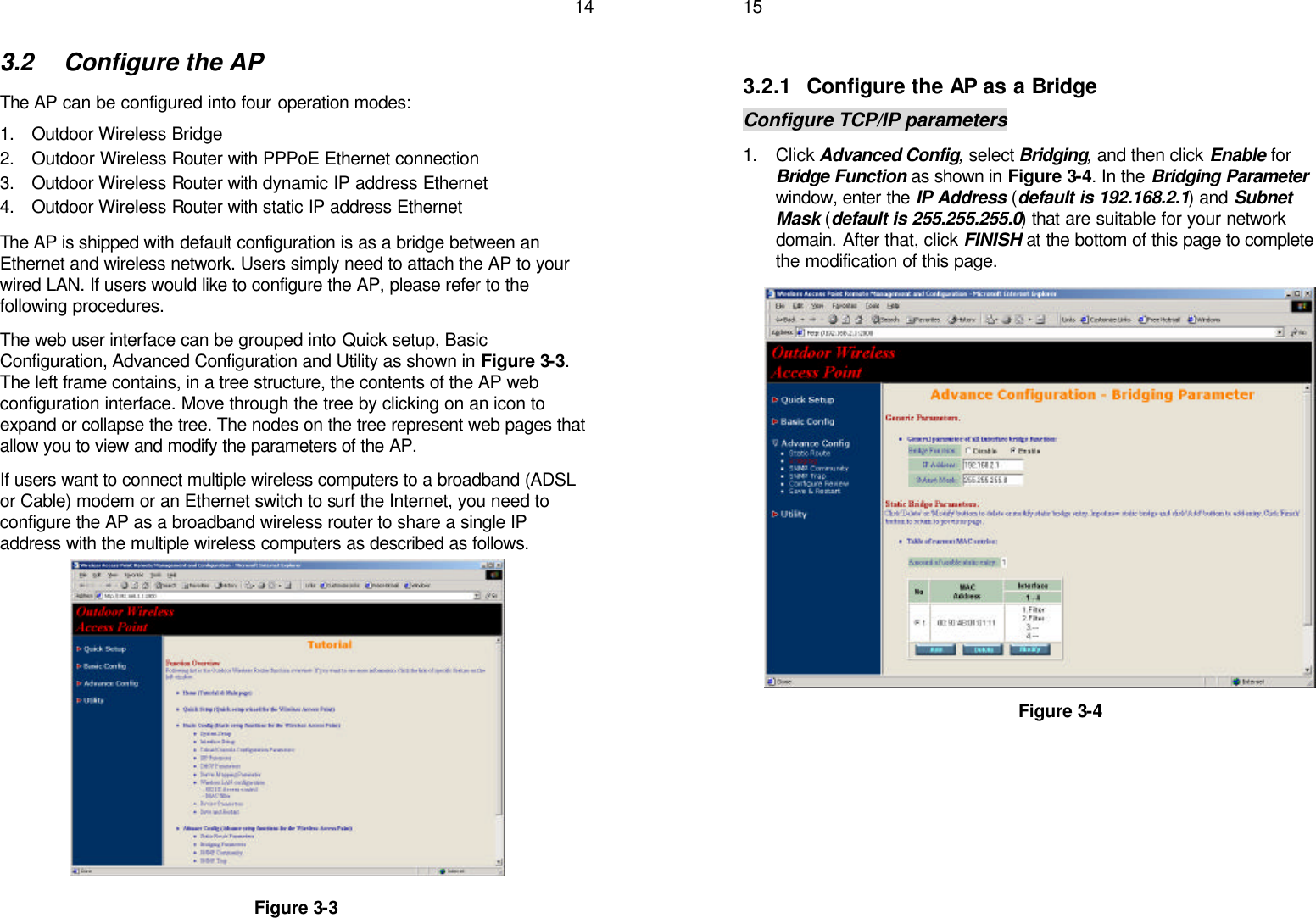
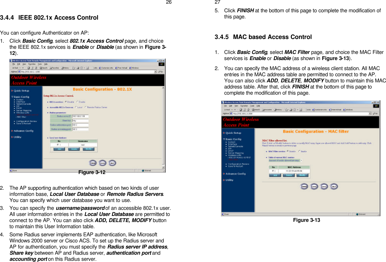
![12Chapter 3. Initial Configuration This chapter describes how to easy setup and configure the Wireless Broadband Access Point (AP) initially. The AP can be configured into a bridge and a broadband wireless router to meet different applications. Users can use a wired LAN-attached computer to configure the AP through a web browser or a telnet session on a LAN computer. In this chapter, we only describe how to quickly configure the AP with a web browser. For detailed descriptions of the many configuration parameters and network configuration, refer to Chapter 4. 3.1 Configure Requirements The AP is shipped with configuration that can be utilized right out of the box. Default configuration is as a bridge between an Ethernet and wireless network. Users simply need to attach the AP to your wired LAN. If users would like to configure the AP, please refer to the following procedures. Before setup, we must install AP first 1. Connect power adaptor and power on the AP 2. Connect the Ethernet cable for connecting the AP to the network 3. Connect a computer to the same network with this AP 4. Start your Microsoft Internet Explorer web browser program from a LAN-attached computer. To access the web interface of the AP, you have to disable Access the Internet using a proxy server function in Windows 2000 [Control Panel / Internet Options / Connections/LAN Settings] as shown in Figure 3-1. 5. Type the IP address and HTTP port of the AP (default port is 2000, IP is 192.168.2.1) in the address field (http://192.168.2.1:2000/) and press Enter. Make sure that the IP addresses of AP and your computer are in the same subnet. 6. After the connection is established, you will see the user identification window as shown in Figure3-2, and key-in the proper User Name and Password to see the web user interface of the AP. The default user name and password is root and root, respectively 13 Figure 3-1 Figure 3-2](https://usermanual.wiki/SendFar-Technology/OAP-04003.Users-Manual-Revised/User-Guide-448680-Page-8.png)
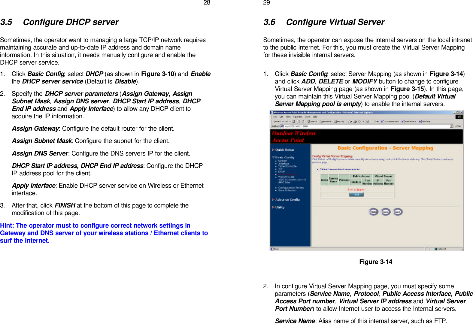
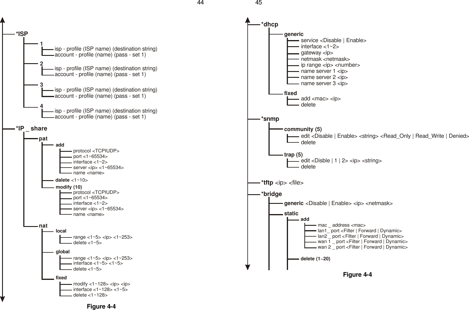
Passwd <pass_conf>*SystemOP _ mode <Router | Bridge | Host>hostname <name>default _ route <ip>PPPPeer_address <ip>User_profile <name> <pass_set0> 43 Figure 4-4 *Interface1address <ip> <netmask>link type <Disable | Ethernet>attrib <Disable | Enable> <Global | Virtual>bridge <Disable | Enable>2address <ip> <netmask>link type <Disable | Ethernet>attrib <Disable | Enable> <Global | Virtual>bridge <Disable | Enable>lanwan1address <ip> <netmask>link type <Disable | Ethernet | PPP | PPPoE>attrib <Disable | Enable> <Global | Virtual>bridge <Disable | Enable>ether_interface <interface>ISP <ISP Index> <dialup timeout> <Dial priority>2address <ip> <netmask>link type <Disable | Ethernet | PPP | PPPoE>attrib <Disable | Enable> <Global | Virtual>bridge <Disable | Enable>ISP <ISP Index> <Idle disconnect time> <Dial priority>ether_interface <interface>*PPPUser_editmodify (5)profile <name> <pass_set0>deleteaddress_poolip_pool <ip> <1~127>authenticate <Userpool | RADIUS> <Userpool | RADIUS>assign_address <Address_Pool | RADIUS> <Address_Pool | RADIUS>](https://usermanual.wiki/SendFar-Technology/OAP-04003.Users-Manual-Revised/User-Guide-448680-Page-23.png)
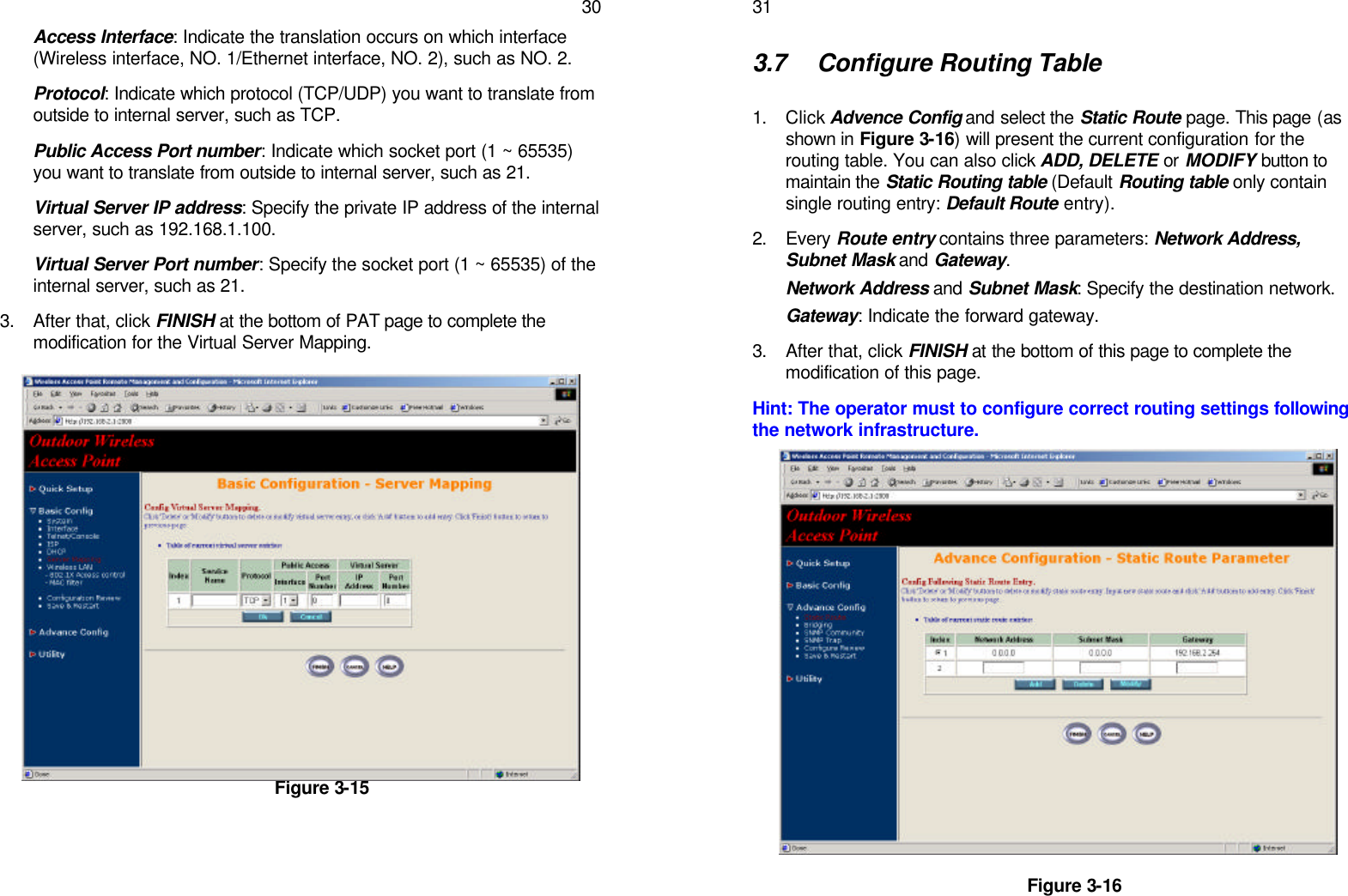
![46 Figure 4-4 modify (20)mac _ address <mac>lan1_ port <Filter | Forward | Dynamic>lan2 _ port <Filter | Forward | Dynamic>wan 1 _ port <Filter | Forward | Dynamic>wan 2 _ port <Filter | Forward | Dynamic>stpmodule <Disable | Enable>bridge <number>lan _ port <1~2> <Disable | Enable> <number>wan _ port <1~2> <Disable | Enable> <number>activate _ stp <CR>WLANchannel <1~14>weprequired <Disable | Enable>rts Threshold <0~3000>frag Threshold <256^2346>SSID <string>station Name <string>defaultkeyId <1~4>defaultkeys <1~4> <hex> 47 Figure 4-4 *Show: Show the current configuration valuesinterfacePPPip _ sharedhcpsnmpbridgeisprun*reset - defaultwriterebootsusys infoPing <ip> [1~65534| - t] [1~1999]exitconfigurationmax _ user <1~5>telnet_port <1~65534>console _ port <com 1 | com 2 >user _ profileaddattrib <13~30><command | Menu><VT100 | ANSI | LINUX | XTerm>source <-1~10>profile <name> <pass _ conf> <Level 1 | Level 2 | Level 3 | Unlimited>delete (1~5)attrib <13~30><command | Menu><VT100 | ANSI | LINUX | XTerm>source <-1~10>profile <name> <pass _ conf> <Level 1 | Level 2 | Level 3 | Unlimited>legal - addressmodify <1~10> <ip>delete <1~10>modifyattrib <13~30><command | Menu><VT100 | ANSI | LINUX | XTerm>source <-1~10>profile <name> <pass _ conf> <Level 1 | Level 2 | Level 3 | Unlimited>](https://usermanual.wiki/SendFar-Technology/OAP-04003.Users-Manual-Revised/User-Guide-448680-Page-25.png)