SendTek CEV75XCES76X EoC Coax MDU Wi-Fi Voice Endpoint User Manual CEV 750 UME 20130722 FCC
SendTek Corporation EoC Coax MDU Wi-Fi Voice Endpoint CEV 750 UME 20130722 FCC
SendTek >
Users Manual

EoC MDU
Wi-Fi Voice Endpoint
User’s Guide
V1.0

- 1 -
F
FC
CC
C
S
ST
TA
AT
TE
EM
ME
EN
NT
T
This device complies with Part
15 of the FCC Rules.
Operation is subject to the following two conditions:
(1) This device may not cause harmful interference,
and
(2) This device must accept any interference received,
including interference that may cause undesired
operation.
NOTE: This equipment has been tested and found to
comply with the limits for a Class A digital device,
pursuant to Part 15 of the FCC Rules. These limits are
designed to provide reasonable protection against harmful
interference in a residential installation. This equipment
generates, uses, and can radiate radio frequency energy
and, if not installed and used in accordance with the
instructions, may cause harmful interference to radio
communications. However, there is no guarantee that
interference will not occur in a particular installation. If
this equipment does cause harmful interference to radio or
television reception, which can be determined by turning
the equipment off and on, the user is encouraged to correct
the interference by one or more of the following measures:
--Reorient or relocate the receiving antenna.
--Increase the separation between the equipment and
receiver.
--Connect the equipment into an outlet on a circuit
different from that to which the receiver is connected.
--Consult the dealer or an experienced radio/TV
technician for help
- 2 -
CAUTION:Any changes or modifications
not expressly approved by the party
responsible for compliance could void the
user’s authority to operate the equipment.
- 3 -
Introduction
This EoC (Ethernet over Coax) MDU Wi-Fi Voice
endpoint connects the telephone, wireless and
Ethernet devices to a high speed access for Internet
access. This endpoint brings you the latest Ethernet
compatible technology that uses the coaxial cable as
the network's physical wiring thereby eliminating the
need to install new wiring. It is designed to operate on
the coaxial TV cable installed in building.
This endpoint is to connect PCs, telephone and
wireless devices to broadband access of cable
operators by simply plugging into the existing coaxial
F-Type connector in home.
Features
• Plug & Play
• Using existing coaxial TV cable to provide in-
building distribution network of broadband access
• Shares Internet access and cable TV video
• 1 port connection Support 700Mbps Ethernet over
Coax (EoC)
• 2 Standard 10/100BaseT Fast Ethernet ports for
connecting to PC or Set-Top-Box(STB)
• 1 Phone Port for VoIP Voice Service
• IEEE 802.11 b/g/n Wi-Fi MIMO Interface
• Configurable QoS, Tag VLAN, Bandwidth Control
• DHCP Option82 and Snooping Support
• Statistics and Status Information Support
- 4 -
HARDWARE INSTALLATION
Parts Names and Functions
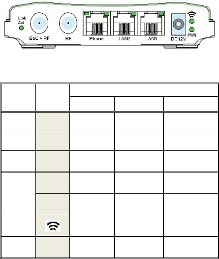
LED Indicators on the Rear Panel
Status
Port LED ON Flashing OFF
DC12V PWR Power ON N/A Not powered
LAN1 LAN1 Link Receive or
Transmit
Disconnect or
Link fail
LAN2 LAN2 Link Receive or
Transmit
Disconnect or
Link fail
Left Link N/A Disconnect or
Link fail
Phone
Right Connected Call Progress No Call
Wi-Fi Link Receive or
Transmit
Disconnect or
Link fail
EoC +
RF
Link
Act Link Receive or
Transmit
Disconnect or
Link fail
- 5 -
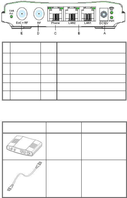
Ports on the Rear Panel
Port Name Type Functions
A DC12V DC Connect to the power adapter plug.
B LAN1/LAN2 RJ-45 Connect to Ethernet port on PC or
Set-Top-Box for Internet Access.
C Phone RJ-11 Connect to Telephone Set
D RF F Connect to TV
E EoC + RF F Connect to F-Connector on wall
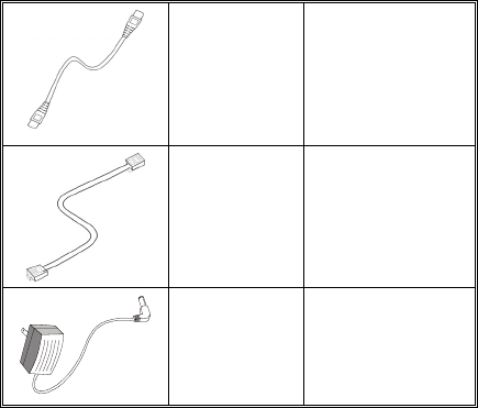
Essential Hardwares
Items Included Description Purpose
EoC MDU
Wi-Fi Voice
Endpoint
Main Unit
Coaxial
Cable
(F-Type/
RG-59U)
Connects from
EoC+RF port to
coax F-Type
connector on the
wall outlet.
- 6 -
CAT5
Ethernet
cable
Connects from
LAN port to
Ethernet enabled
devices as PC
or STB
Telephone
wire
Connects Phone
port to phone set
DC12V
Power
adapter
Connects from
Power port of
the main unit
into a wall outlet
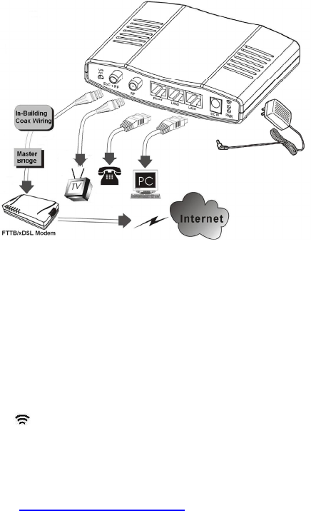
Hardware Connections
1. Select a convenient location for the EP near the
PC or Ethernet device to which it will be
connected. The EP should be kept away from
excessive heat.
2. Using one coaxial cable to connect the EoC+RF
port to F-Type connector on the wall. Using
another coaxial cable to connect the other F-type
RF port to TV set (optional).
3. Connect the LAN1/LAN2 port to your Ethernet-
equipped device.
4. Connect the telephone to Phone port.
5. Connect the power adapter to the DC12V port
into a wall outlet.
- 7 -
The figure above shows how to connect PON/
FTTx/xDSL modem, user’s TV and PC to the WiFi
endpoint via in-building coaxial cable network.
Now you should have connected the LAN port,
EoC port and the DC12V port to the appropriate
devices or lines. LED will be as:
PWR ON
LAN ON
(WiFi) ON
Phone (Left) ON
EoC+RF Link/Act ON
For more information on LEDs, see section entitled
"LED Indicators on the Rear Panel"

- 8 -
TROUBLESHOOTING
Please refer to the list below to aid in troubleshooting.
The PWR (green) LED is off.
Make sure the power adapter is properly plugged
into a live electrical outlet.
The LAN (Ethernet) LED is off.
Make sure the connection to LAN port is secure.
The Ethernet device to which you are connected
should be powered on and properly configured.
The EoC+RF Link/Act LED is off
Check the connection to EoC+RF port is secure.
The device to which you are connected should be
powered on and properly configured.
Make sure the quality of coaxial connector and
cable is good.
The (WiFi) LED is off.
Power off then power on the endpoint device.
Cannot connect to the Wi-Fi AP.
Make sure if the settings are correct by
re-configuring the endpoint device via Master.
Note the default SSID is “WIFI-EP” and the
default WPA/WPA2 pre-shared key is
“endpoint” before applying (Reconfig) new
settings.
The Phone (Left) LED is off.
- 9 -
Check the VoIP SIP registered account is correct.

- 10 -
SPECIFICATIONS
Standards
IEEE 802.3u 100BaseT Fast Ethernet
Ethernet over Coax (EoC) compliant
IEEE 802.11b/g/n compliant
Data Rates
EoC: 320Mbps throughput / 700 Mbps Phy Rate
Ethernet: 10/100 Mbps
Wi-Fi : 300Mbps maximal
Transmission Range
EoC: Up to 70dB attenuation
Ethernet: 100 meters maximum
Power Consumption
12V DC, Less than 8 watt
Certifications
CE, FCC Part 15
LEDs
Power
(WiFi) Link/Activity
Ethernet Link/Activity
EoC Link/Activity
Phone Link and Call Progress
Connectors
Two F-Type connectors, one for connecting
with Master device, and one for TV Bypass
Two RJ-45 for 10/100Mbps Ethernet
One RJ-11 for Telephone