Sennco Solutions 160001 Sennco Solutions Model 160001 User Manual Exhibit D Users Manual per 2 1033 b3
Sennco Solutions, Inc. Sennco Solutions Model 160001 Exhibit D Users Manual per 2 1033 b3
Exhibit D Users Manual per 2 1033 b3
Prepared 10/2016 1 Patent pending
14407 Coil Plus Dr, Unit A | Plaineld, IL 60544
www.sennco.com | techsupport@sennco.com
815.577.3400 | Toll free 866.736.6261
Mon - Fri 9AM - 5PM CST
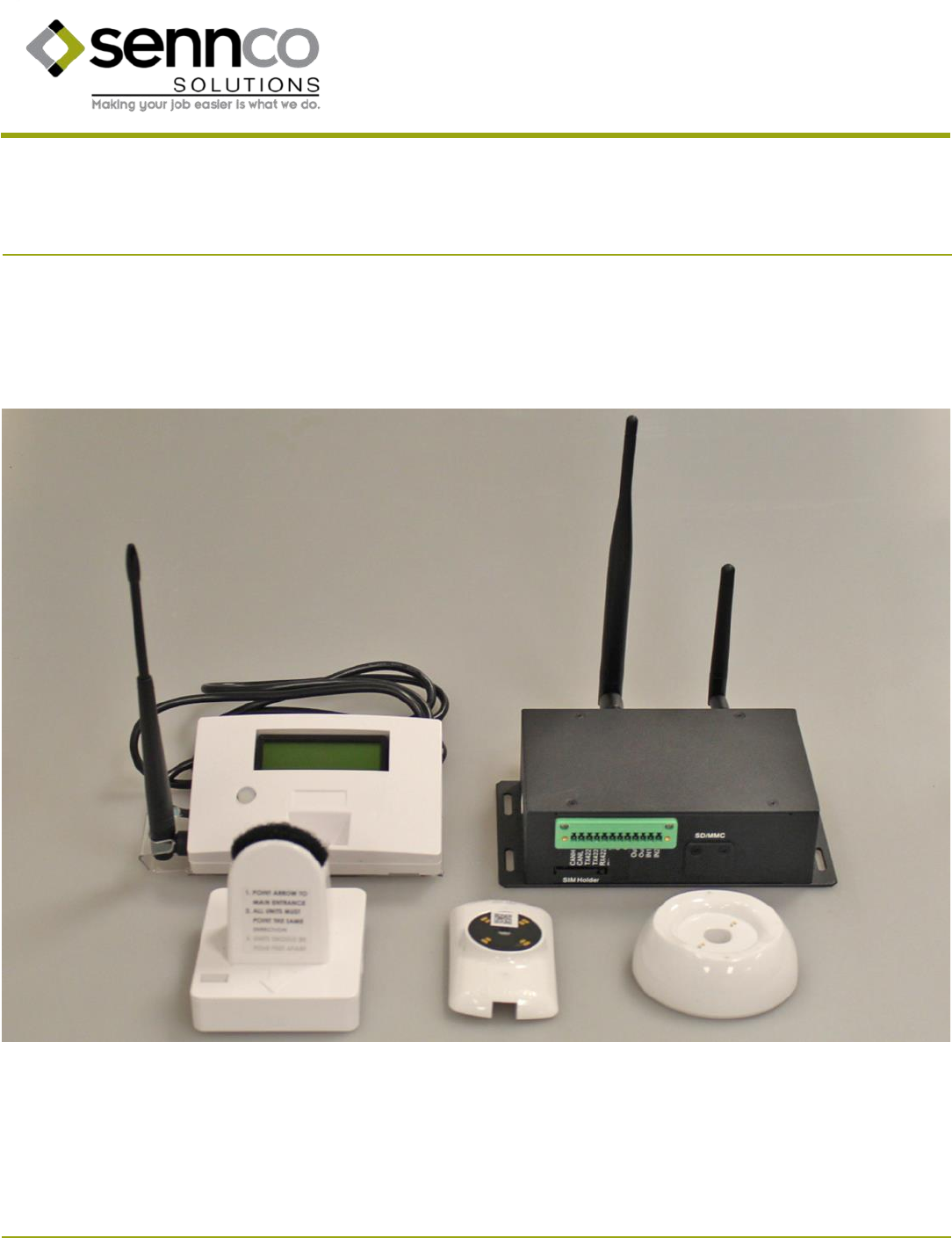
Instrucons for Genesis Wireless Security System™
Power & Alarm Soluon with Data Analycs Capability
Code 120-010 Rev 5 COPYRIGHT © 2016 Sennco Soluons, Inc. All rights reserved.
Prepared 10/2016 2 Patent pending
14407 Coil Plus Dr, Unit A | Plaineld, IL 60544
www.sennco.com | techsupport@sennco.com
815.577.3400 | Toll free 866.736.6261
Mon - Fri 9AM - 5PM CST
Nocaons
Any changes/modicaons to this equipment not approved by Sennco Soluons Inc. could void the user’s
authority to operate the equipment.
This device complies with Industry Canada license-exempt RSS standard(s). Operaon is subject to the
following two condions: (1) this device may not cause interference, and (2) this device must accept any
interference, including interference that may cause undesired operaon of the device.
Le présent appareil est conforme aux CNR d'Industrie Canada applicables aux appareils radio exempts de
licence. L'exploitaon est autorisée aux deux condions suivantes : (1) l'appareil ne doit pas produire de
brouillage, et (2) l'ulisateur de l'appareil doit accepter tout brouillage radioélectrique subi, même si le
brouillage est suscepble d'en compromere le fonconnement.
Patents:
Patent No.: US 8,279,077 B1 Patent No.: US 9,019,113 Patent No.: US 7,154,039
Patent No.: US 8,558,714 B1 Patent No.: US 9,303,809
Sennco Soluons, Inc. is not held liable for any rmware or soware changes implemented by the displayed
product’s manufacturer, distributor, or reseller.
Warning: System components should only be powered by the provided power supplies. Use of other power
supplies can result in a risk of electrical re and shock hazard.
Component Model FCC ID IC ID Rang
Main alarm+Data monitor Model: 160001 COI-160001 20574-160001 24V 2.71A
Cradle Model: 150002 N/A N/A 5V 3A
Sensor head Model: 150003 COI-150003 20574-150003 5V 2A max
Security Perimeter Dome Model: 150005 COI-150005 20574-150005 24V 2.71A
Cauon: DO NOT connect devices that draw more than 2A.

Prepared 10/2016 3 Patent pending
14407 Coil Plus Dr, Unit A | Plaineld, IL 60544
www.sennco.com | techsupport@sennco.com
815.577.3400 | Toll free 866.736.6261
Mon - Fri 9AM - 5PM CST
Warning! The Main Alarm and Sensor Heads contain Lithium Ion (Li-ion) baery packs.
Do not charge pack unaended.
Do not reverse-charge or reverse-connect.
Do not short circuit.
Do not expose baery to direct sunlight.
Do not dispose of in re.
Do not insert baeries with dierent connector.
Do not heat, deform, solder, disassemble, or modify.
Do not dispose of in trash or single stream recycling.
Stop using if the baery pack expands or temperature exceeds 160°F (70°C).
Disposal regulaons may vary by locaon. Contact your local waste facility or recycling center for details
on safe disposal opons.
The user is fully responsible for the safe storage, use, and disposal of the Li-ion baeries contained in this
product.

Prepared 10/2016 4 Patent pending
14407 Coil Plus Dr, Unit A | Plaineld, IL 60544
www.sennco.com | techsupport@sennco.com
815.577.3400 | Toll free 866.736.6261
Mon - Fri 9AM - 5PM CST
Table of Contents
I. Parts List (What does it come with?)
A. Main Alarm……………………………………………………………………...……..……. Page 5
B. Security Perimeter Dome………………………….………………………………….. Page 5
C. Sensor head…………………………………………………………………….……………. Page 5
D. Cloud Interface..……………………………………………………………..……………. Page 5
E. Cradle………………………………………………………………………..…………………. Page 6
II. Descripon of Alarm (What is this part?)
A. Main Alarm…………………………………………………………………...……..………. Page 7
B. Security Perimeter Dome…………………………………………….……………..… Page 8
C. Sensor head…………………………………………………………………………….……. Page 8
D. Cradle…………………………………………………………………………….…………….. Page 9
E. Cloud Interface……………………………………………………………….…….……. Page 10
III. Set Up (Where do I put these?)
A. Cradles………………………………………………………………..……………………… Page 11
B. Cloud Interface…………………………...………………………………………..……. Page 15
C. Main Alarm……………..……………………………………………………...……...…. Page 15
D. Security Perimeter Domes…………………………..………...…………………… Page 16
E. Sensor heads……………………………………..……………………………………….. Page 17
F. Connecng sensor heads to Cordwinder cables.…………………………. Page 18
G. Disconnecng sensor heads from Cordwinder cables……………….... Page 18
IV. Teaching DaKeys (How do I program the DaKey?)
A. Teaching the rst DaKey………………………………………………….………….. Page 19
B. Teaching addional DaKeys……………………………………………….….……. Page 19
V. Reseng the System (How do I program the alarm?)……………..……….……..…. Page 20
VI. Sensor Head Alarm…………………………………………………………………………………….. Page 21
VII. Silencing the Main Alarm (How do I make it stop?)……………..………………...….. Page 21
VIII. Disarming the Main Alarm………………………………………………………………….………. Page 22
IX. Hard Reset (How do I reset it?)…………………………………………………………………... Page 22
X. Points of Sensing
A. Micro USB power cable……………………………………………………..……….. Page 23
B. Sensor head plunger…………………………………..………………………………. Page 23
C. Sensor head proximity………………………………………………………………… Page 23
Prepared 10/2016 5 Patent pending
14407 Coil Plus Dr, Unit A | Plaineld, IL 60544
www.sennco.com | techsupport@sennco.com
815.577.3400 | Toll free 866.736.6261
Mon - Fri 9AM - 5PM CST
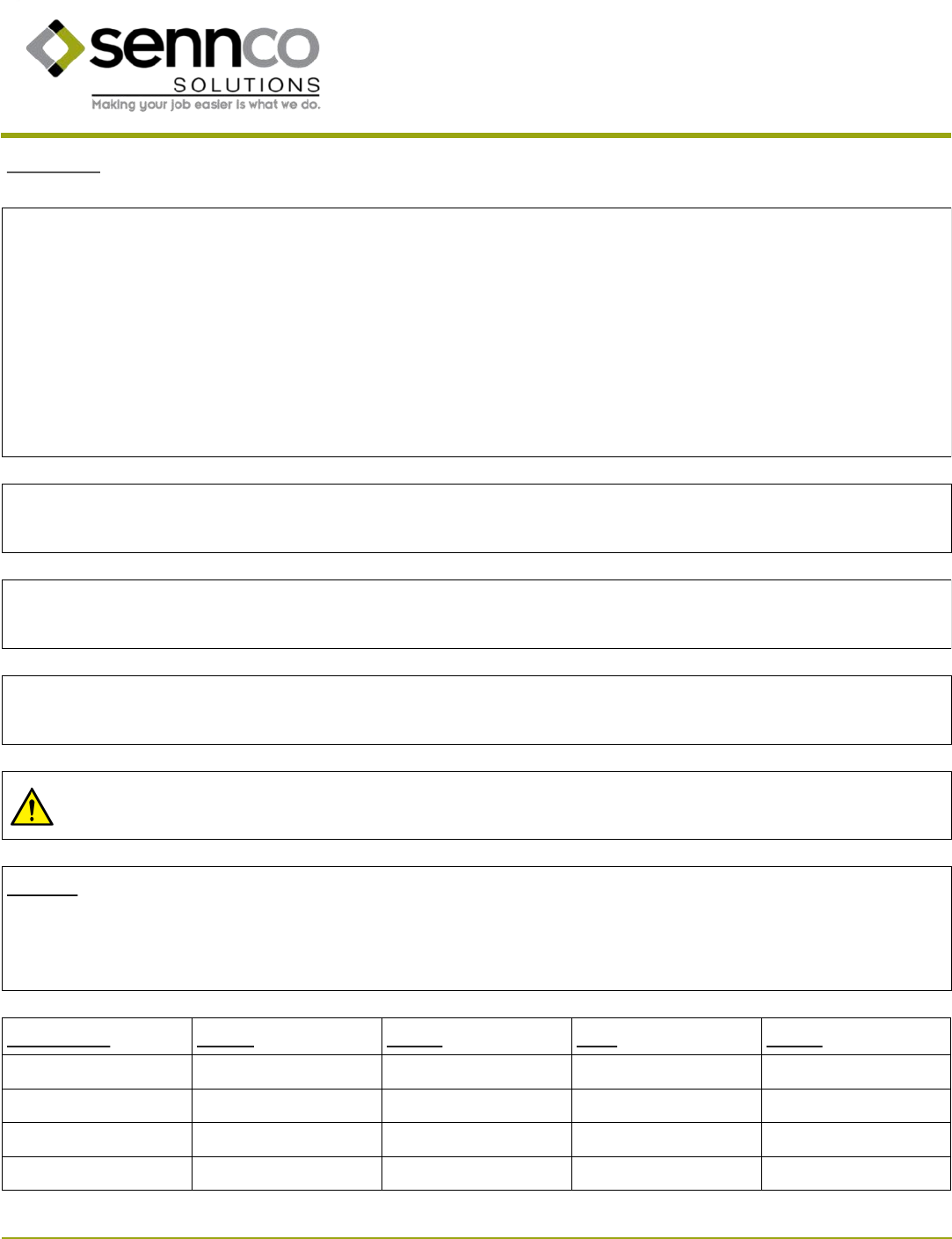
I. Parts List
Main alarm unit
A. Main alarm
Security Perimeter Dome AC power cable for Security Perimeter Dome
B. Security Perimeter Dome
D. Cloud Interface
C. Sensor head
DaKey
Sensor head shielding Sensor head Sensor head adhesive WPWR cable Tether Disconnect Key
AC power cable for Main Alarm
*Actual cable may dier from image.
*Actual cable may dier from image.
Cloud Interface AC power cable Cloud Interface antennas
WLAN
3G/GPRS
*Actual cable may dier from image.
Prepared 10/2016 6 Patent pending
14407 Coil Plus Dr, Unit A | Plaineld, IL 60544
www.sennco.com | techsupport@sennco.com
815.577.3400 | Toll free 866.736.6261
Mon - Fri 9AM - 5PM CST
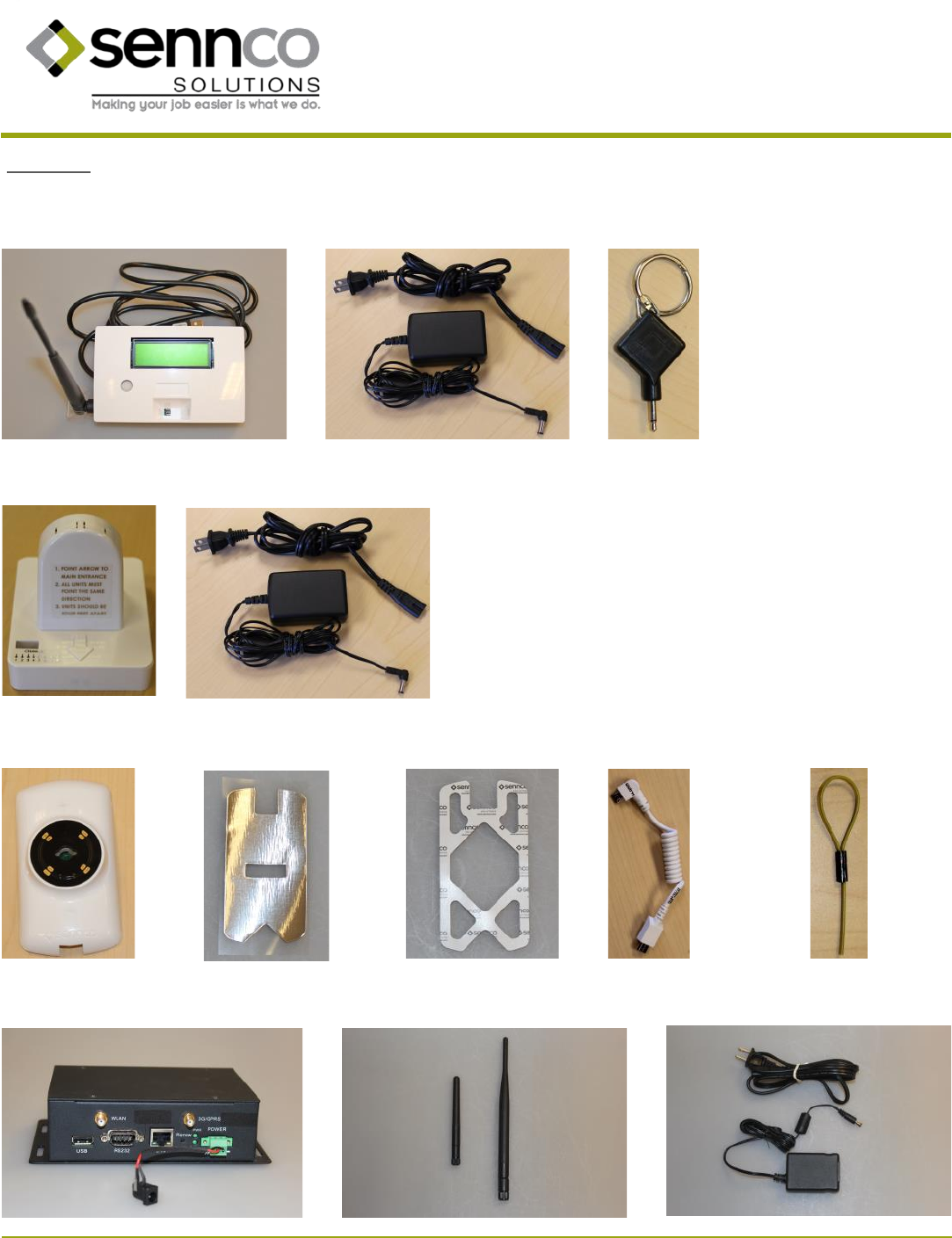
E. Cradle
Other cradle mounng opons are available.
Cordwinder Cordwinder adhesive
*Cordwinder model may
vary.
*Cordwinder adhesive may
vary.
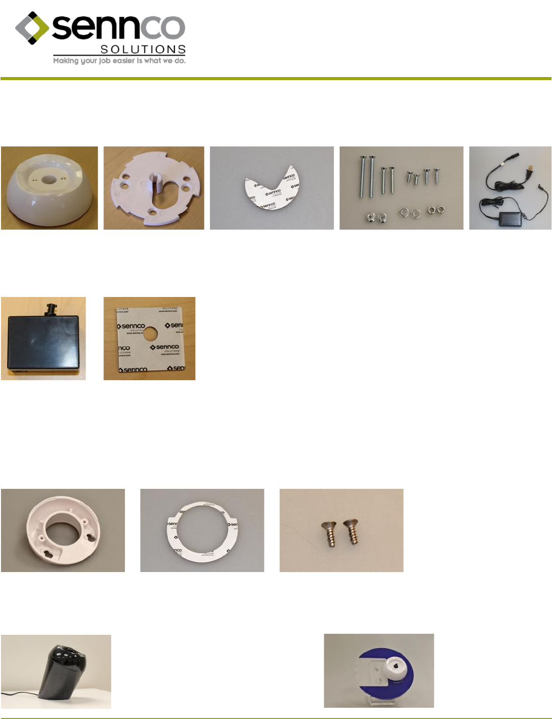
Above Counter Post
Refer to instrucon code 120-007
Display Circle
Refer to instrucon code 120-012
Cradle mounng plate
Cradle AC power cable Cradle mounng plate adhesive
*Actual cable may vary.
Cradle mounng plate hardware
Oponal parts:
0.5” screws for mounng cradle mounng plate on wedge Wedge adhesive Wedge
Prepared 10/2016 7 Patent pending
14407 Coil Plus Dr, Unit A | Plaineld, IL 60544
www.sennco.com | techsupport@sennco.com
815.577.3400 | Toll free 866.736.6261
Mon - Fri 9AM - 5PM CST
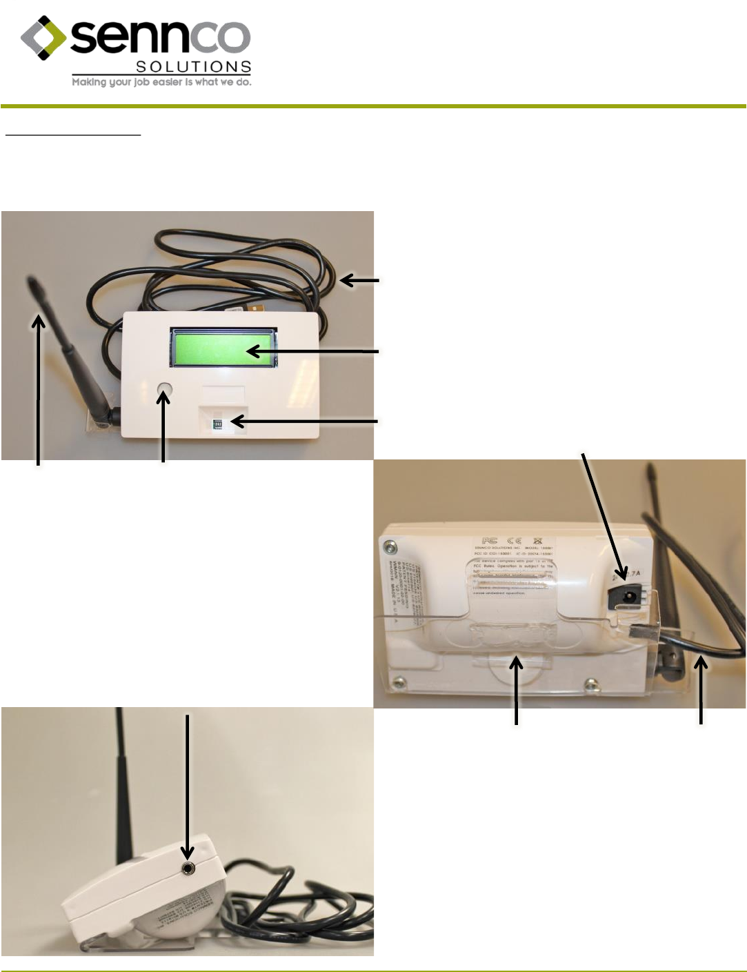
II. Descripon of Alarm
Buon
LCD
DIP switches
Antenna
DC power port
DaKey port
A. Main alarm + Data Monitor
Rated 24V 2.71A max
USB-A cable
USB-A cable Mounng plate (clear)
Prepared 10/2016 8 Patent pending
14407 Coil Plus Dr, Unit A | Plaineld, IL 60544
www.sennco.com | techsupport@sennco.com
815.577.3400 | Toll free 866.736.6261
Mon - Fri 9AM - 5PM CST
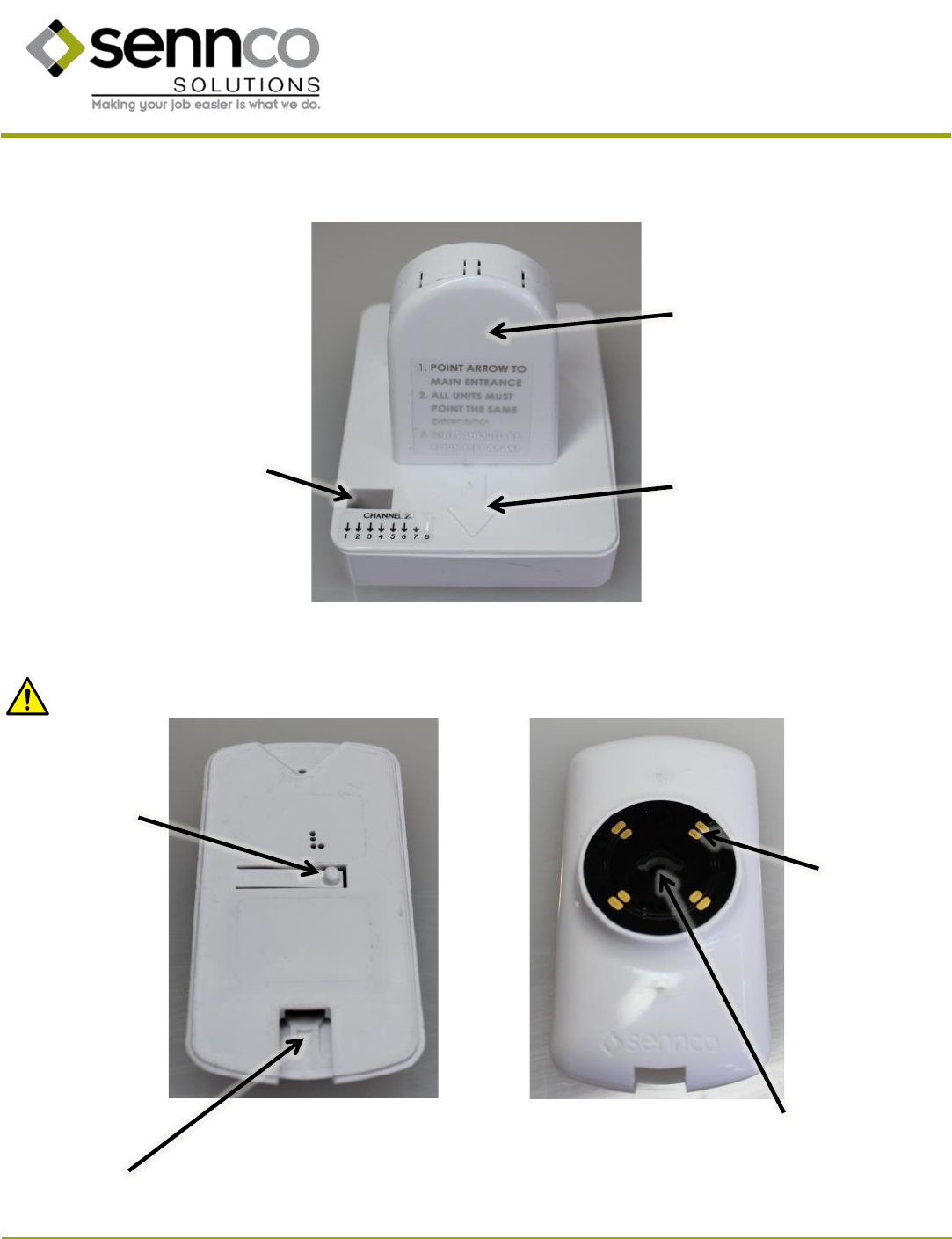
Antenna
B. Security Perimeter Dome
DIP switches
Antenna (internal)
Arrow (all Security Perimeter
Domes must face the same
direcon)
C. Sensor head
Plunger switch
Micro USB
charging port
Cordwinder cable end
port
Charging
contacts
Rated 24V 2.71A max
Cauon: DO NOT connect devices that draw more than 2A.
Rated 5V 2A max
Prepared 10/2016 9 Patent pending
14407 Coil Plus Dr, Unit A | Plaineld, IL 60544
www.sennco.com | techsupport@sennco.com
815.577.3400 | Toll free 866.736.6261
Mon - Fri 9AM - 5PM CST
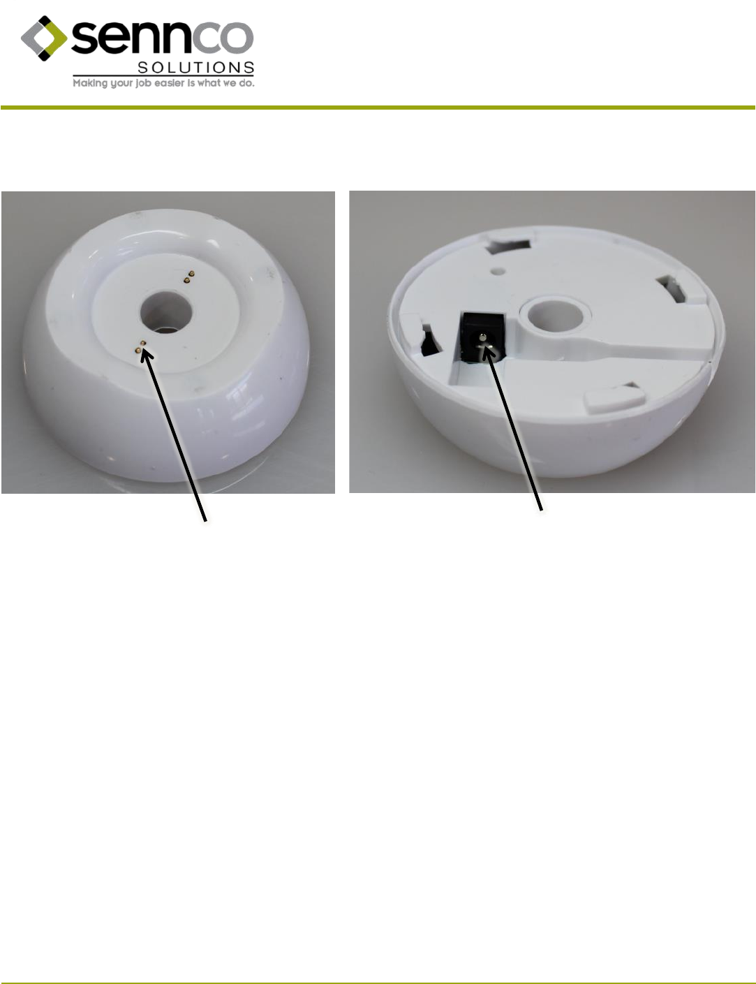
D. Cradle
Charging
contacts
DC power port
Rated 5V 3A max
Prepared 10/2016 10 Patent pending
14407 Coil Plus Dr, Unit A | Plaineld, IL 60544
www.sennco.com | techsupport@sennco.com
815.577.3400 | Toll free 866.736.6261
Mon - Fri 9AM - 5PM CST
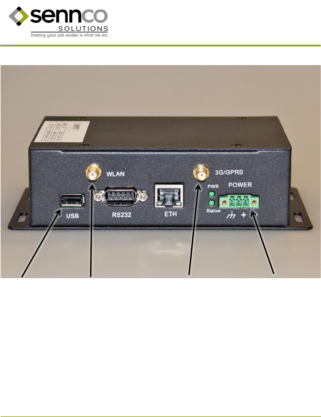
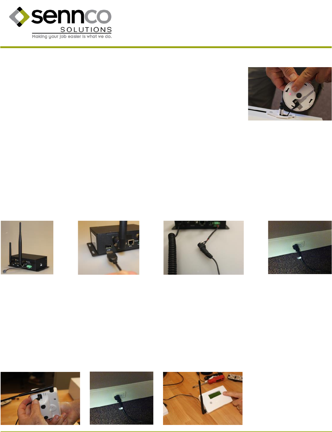
E. Cloud Interface
USB port
WLAN antenna
port (shorter)
DC power port
3G/GPRS antenna
port (taller)
Prepared 10/2016 11 Patent pending
14407 Coil Plus Dr, Unit A | Plaineld, IL 60544
www.sennco.com | techsupport@sennco.com
815.577.3400 | Toll free 866.736.6261
Mon - Fri 9AM - 5PM CST
III. Set Up
A. Cradles
Note: Main Alarm, Cloud Interface, and cradles should be located at the same height as much as possible.
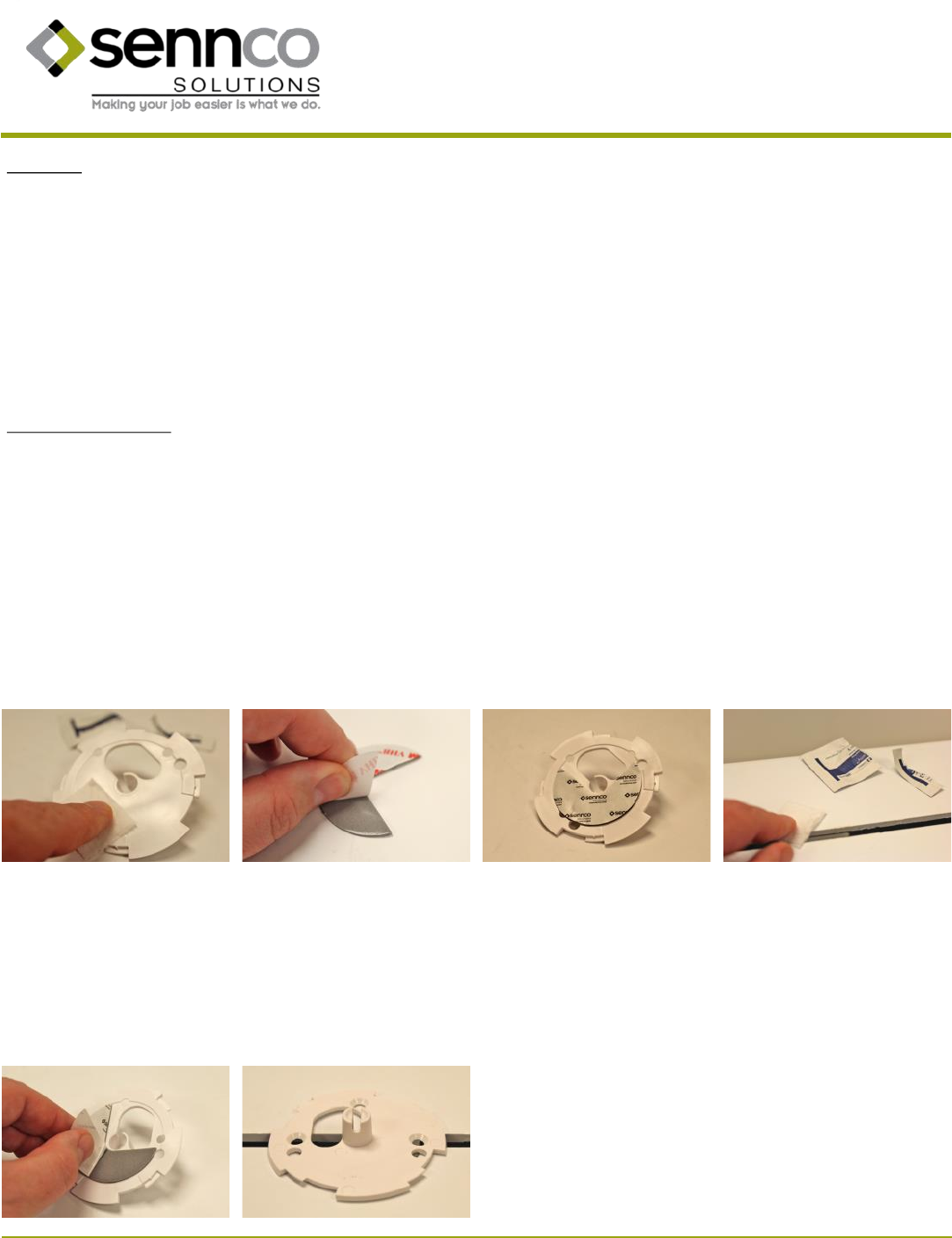
1. Clean the at side of the cradle mounng plate using an alcohol wipe. Dry with a clean cloth.
2. Remove the backing from one side of the cradle mounng plate adhesive.
3. Apply the adhesive to the at side of the cradle mounng plate. Make sure that the cutout on the adhesive is lined up with the cutout in the
paern on the mounng plate. Press rmly for 15 seconds for a stronger adhesive bond.
4. Using an alcohol wipe, clean the surface where the cradle will be placed.
Cradle mounng opon 1: Mounng plate using adhesive (no wedge)
5. Remove the remaining backing from the adhesive.
6. Center the cradle mounng plate over the posion. The slot in the center post of the cradle mounng plate should be open at the top and
the large opening in the cradle mounng plate should be at the top le. Press rmly for 15 seconds for a stronger adhesive bond.
Prepared 10/2016 12 Patent pending
14407 Coil Plus Dr, Unit A | Plaineld, IL 60544
www.sennco.com | techsupport@sennco.com
815.577.3400 | Toll free 866.736.6261
Mon - Fri 9AM - 5PM CST
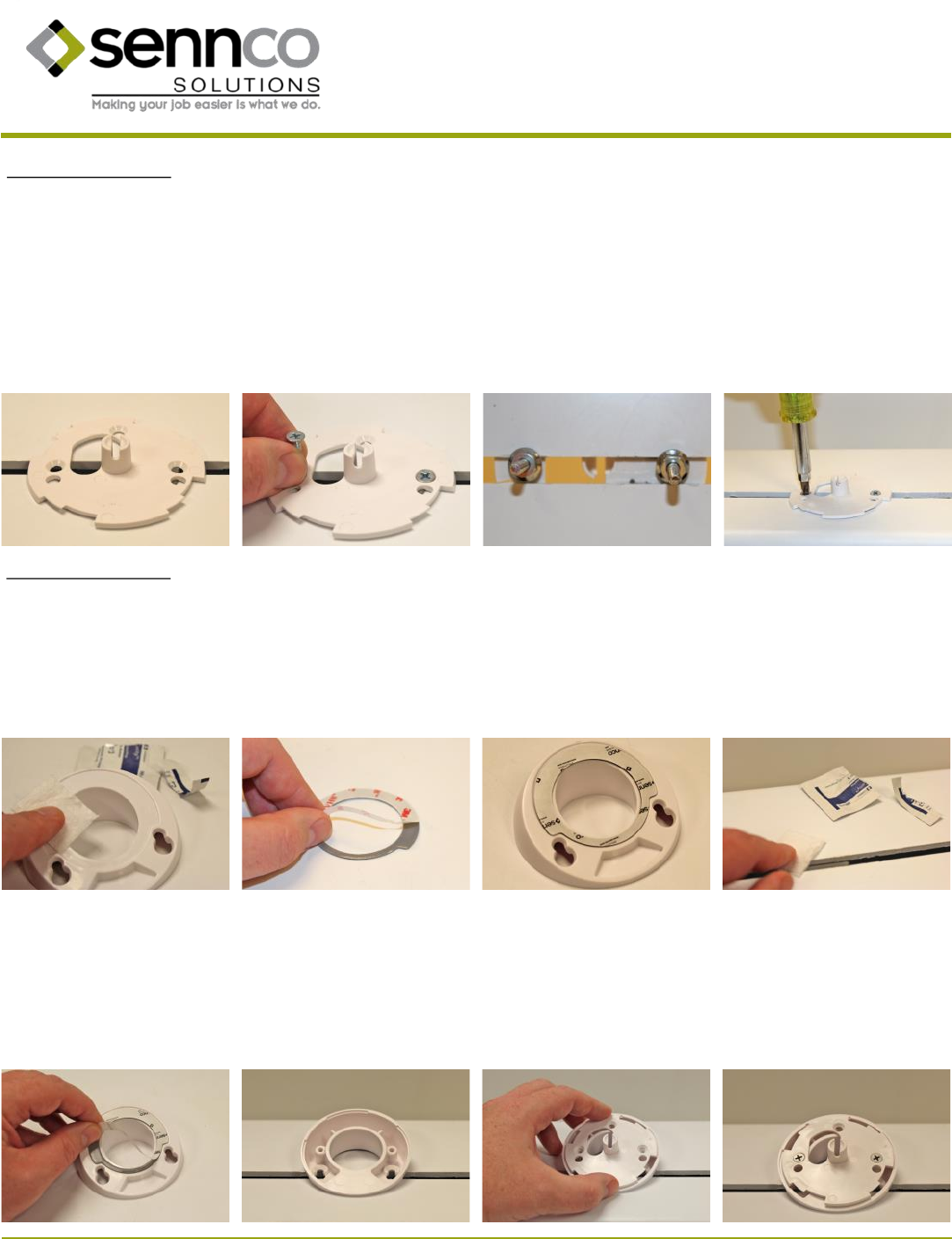
Cradle mounng opon 2: Mounng plate using screws (no wedge)
1. Center the cradle mounng plate over the posion, at side down. The slot in the center post of the cradle mounng plate should be open
at the top and the large opening in the cradle mounng plate should be at the top le. Depending on your xture type you may need to drill
holes for the mounng screws.
2. Insert two appropriate length screws from the mounng kit.
3. Place a washer and nut on each screw underneath the xture.
4. Hold the nut securely with a wrench and use a screwdriver to ghten the screw. Be careful not to overghten. Repeat for the other screw.
Cradle mounng opon 3: Wedge using adhesive
1. Clean the boom of the wedge using an alcohol wipe. Dry with a clean cloth.
2. Remove the backing from one side the wedge adhesive.
3. Apply the adhesive to the boom of the wedge. Press rmly for 15 seconds for a stronger adhesive bond.
4. Using an alcohol wipe, clean the surface with the cradle will be placed. Dry with a clean cloth.
5. Remove the remaining backing from the adhesive.
6. Center the wedge over the posion. The lower side should be to the front. Press rmly for 15 seconds for a stronger adhesive bond.
7. Place the cradle mounng plate (at side down) over the wedge. The slot in the center post of the cradle mounng plate should be open at
the top and the large opening in the cradle mounng plate should be at the top le.
8. Insert the two 0.5” screws. Tighten down with a screwdriver. Be careful not to overghten.
Prepared 10/2016 13 Patent pending
14407 Coil Plus Dr, Unit A | Plaineld, IL 60544
www.sennco.com | techsupport@sennco.com
815.577.3400 | Toll free 866.736.6261
Mon - Fri 9AM - 5PM CST
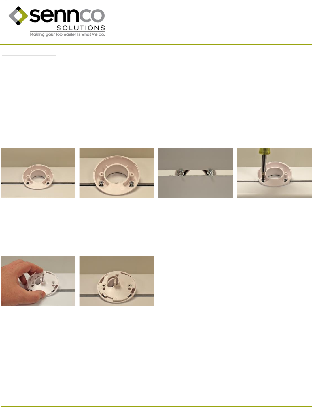
Cradle mounng opon 4: Wedge using screws
1. Center the wedge over the posion. The lower side should be to the front.
2. Insert two appropriate length screws from the mounng kit. (Depending on your xture type you may need to drill holes for the mounng
screws.)
3. Place a washer and nut on each screw underneath the xture.
4. Hold the nut securely with a wrench and use a screwdriver to ghten the screw. Be careful not to overghten. Repeat for the other screw.
5. Place the cradle mounng plate (at side down) over the wedge. The slot in the center post of the cradle mounng plate should be open at
the top and the large opening in the cradle mounng plate should be at the top le.
6. Insert the two 0.5” screws. Tighten down with a screwdriver. Be careful not to overghten.
Cradle mounng opon 5: Above Counter Post
Cradle mounng opon 6: Display Circle
Refer to instrucon code 120-007
Refer to instrucon code 120-012
Prepared 10/2016 14 Patent pending
14407 Coil Plus Dr, Unit A | Plaineld, IL 60544
www.sennco.com | techsupport@sennco.com
815.577.3400 | Toll free 866.736.6261
Mon - Fri 9AM - 5PM CST
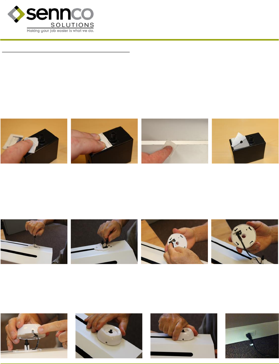
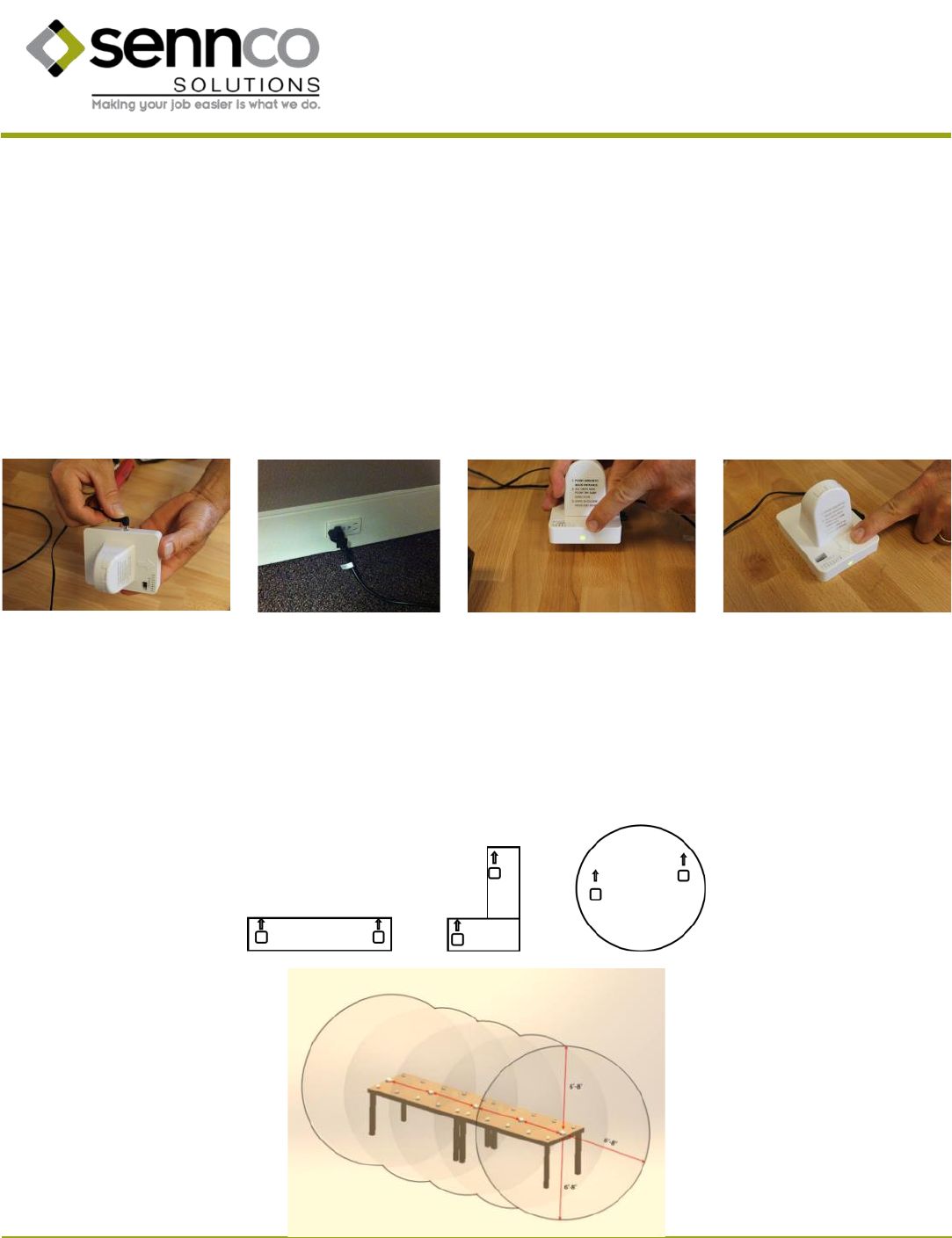
1. Find the Cordwinder. Clean the top of the Cordwinder box where the cable exits using an alcohol wipe. Dry it with a clean cloth.
2. Peel the backing o of the Cordwinder mounng adhesive and secure the adhesive to the Cordwinder. Press rmly for 15 seconds for a
stronger adhesive bond.
3. Using an alcohol wipe, clean the area underneath the xture where the Cordwinder will be placed. Dry with a clean cloth.
4. Peel the backing o of the top of the adhesive and secure the Cordwinder to the underside of the xture so that the cable is centered in the
cradle mounng plate. Press rmly for 15 seconds for a stronger adhesive bond.
5. Pull the cable end up through the large hole in the cradle mounng plate and guide the cable into the slot on the center post of the cable
mounng plate. Slowly allow the cable to retract unl the cable rests on the center post.
6. Find the power cable for the cradle and pull the barrel plug end up through the large hole in the cradle mounng plate.
7. Plug the power cable into the power port on the boom of the cradle.
8. Guide the power cable into the cable keeper.
9. Make sure that the mouse hole is towards the back of the xture.
10. Place the cradle on top of the cradle mounng plate, oset slightly counterclockwise from center.
11. Turn the cradle clockwise unl it locks in place.
12. Plug the power cable into an outlet that has AC power available.
Cradle mounng connued (following mounng opon 1, 2, 3, or 4)
Prepared 10/2016 15 Patent pending
14407 Coil Plus Dr, Unit A | Plaineld, IL 60544
www.sennco.com | techsupport@sennco.com
815.577.3400 | Toll free 866.736.6261
Mon - Fri 9AM - 5PM CST
1. Place the Main Alarm unit in clear line of sight within 50 feet of the display xtures and Security Perimeter Domes. Avoid mounng near the
oor or with large metal objects, metal cabinets, other equipment, etc. in close proximity to the Main Alarm or between the Main Alarm
and the display xtures. The Main Alarm should be at least 2 feet away from the nearest sensor head, and its antenna should be posioned
vercally 90°.
2. The Main Alarm’s USB-A cable should already be plugged into the Cloud Interface and the Cloud Interface should have beeped twice aer
being connected to AC power. (See secon B above.)
3. Plug the barrel plug end of the power cable into the power port on the Main Alarm.
4. Plug the power cable into an outlet that has AC power available.
1. Screw the shorter antenna into the le posion labeled WLAN and the taller antenna into the right posion labeled 3G/GPRS. Posion both
antennas vercally.
2. Plug the USB-A cable from the Main Alarm into the USB port on the Cloud Interface.
3. Plug the barrel plug end of the power cable into the power port on the Cloud Interface.
4. Plug the power cable into an outlet that has AC power available. Listen and conrm Cloud Interface beeps twice.
5. Place the Cloud Interface within reach of the Main Alarm USB-A cable, but make sure the Main Alarm and Cloud Interface antennas are
spaced at least one foot apart. Avoid placing the Cloud Interface inside of cabinets, near the oor or near metal.
C. Main Alarm
13. There is a red LED on the boom of the cradle which will be lit when the cradle is receiving power. This LED is not visible when the cradle is
on the cradle mounng plate.
14. Repeat as necessary for addional cradles.
B. Cloud Interface
Prepared 10/2016 16 Patent pending
14407 Coil Plus Dr, Unit A | Plaineld, IL 60544
www.sennco.com | techsupport@sennco.com
815.577.3400 | Toll free 866.736.6261
Mon - Fri 9AM - 5PM CST
D. Security Perimeter Domes
1. Plug the barrel plug end of the power cable into the power port on the Security Perimeter Dome.
2. Plug the power cable into an outlet that has AC power available.
3. The green LED on the front of the Security Perimeter Dome indicates power is being received.
4. Place the Security Perimeter Dome in posion. (Note: They cannot be placed upside down. )
a) Each Security Perimeter Dome generates a 6 - 8 radius sphere within which the protected devices are safe.
b) Addional Security Perimeter Domes within the same xture should be spaced no more than 3 1/2 feet apart.
c) Each Security Perimeter Dome has an arrow on the front. All Security Perimeter Dome arrows in the system need to point in the
same direcon.
d) Mulple Security Perimeter Dome signals overlap to form a security area as illustrated below.
Place Security Perimeter Domes in clear line of sight within 3 1/2 feet of each other and within 3 feet of the farthest cradle. Avoid mounng
Security Perimeter Domes near the oor or with large metal objects, metal cabinets, other equipment, etc. in close proximity or between the
Security Perimeter Domes and the cradles. If Security Perimeter Domes are mounted below the xture, do not mount them more than 2 feet
below the cradles.
The blue LED on the front of the Security Perimeter Dome indicates wireless signals are being received. Aer the system is set up and the Main
Alarm is powered, the blue LED should ash once about every second to indicate proper operaon.
Prepared 10/2016 17 Patent pending
14407 Coil Plus Dr, Unit A | Plaineld, IL 60544
www.sennco.com | techsupport@sennco.com
815.577.3400 | Toll free 866.736.6261
Mon - Fri 9AM - 5PM CST
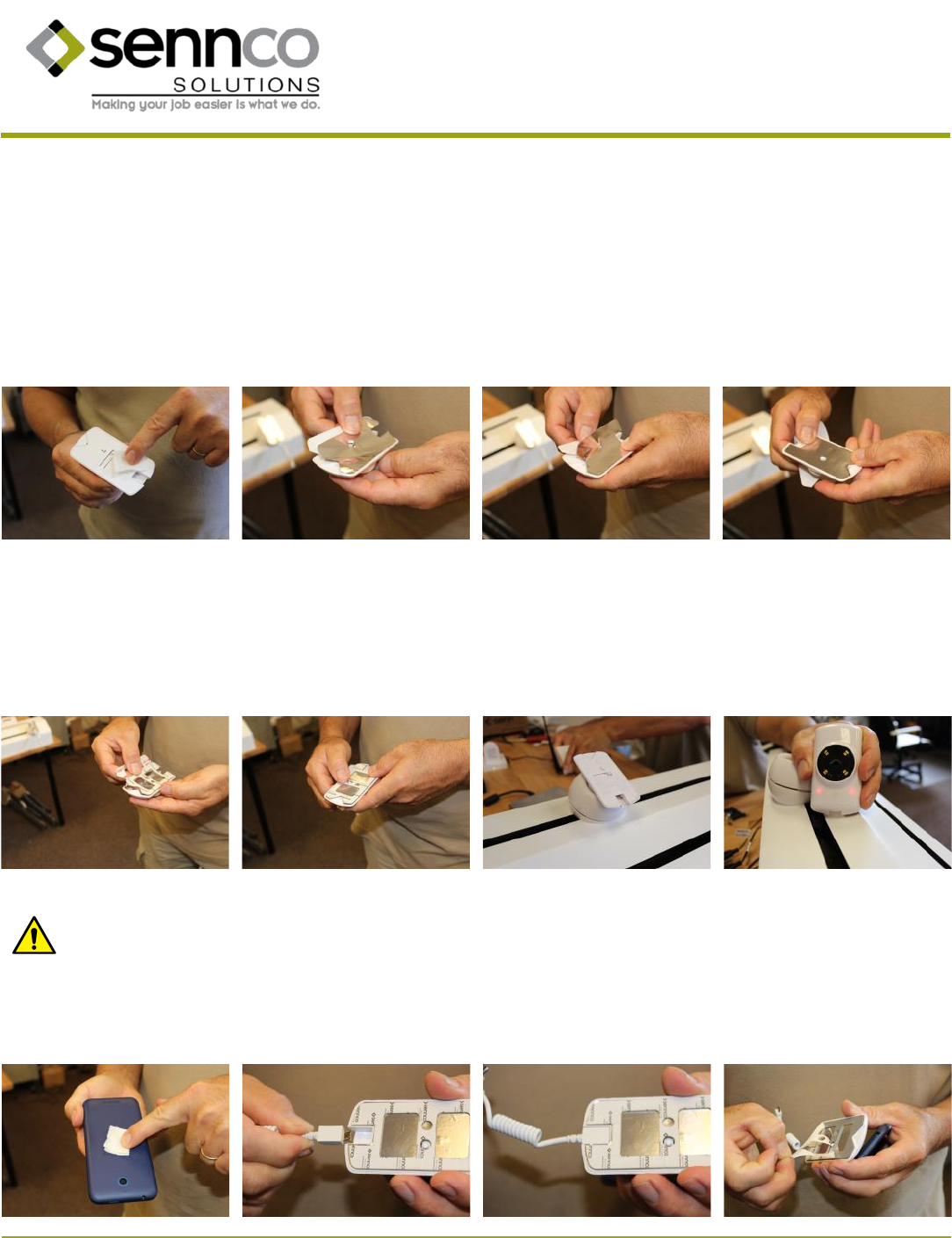
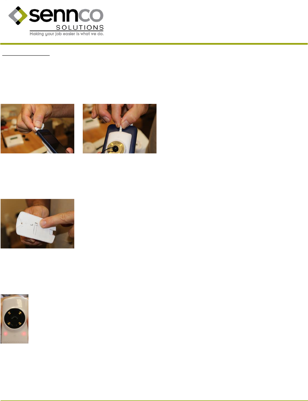
1. Clean the surface of the sensor head’s inside face using an alcohol wipe. Dry with a clean cloth.
2. Peel the backing o of the shielding and carefully line it up with the edge of the sensor head’s inside face. The v notch will be at the top of
the sensor head and the charging port will be at the boom.
3. Smooth down the shielding as you connue to adhere it to the sensor head.
4. Make sure that the shielding is smoothed down and securely adhered across the inside face of the sensor head.
E. Sensor heads
5. Peel the backing o of one side of the sensor head adhesive.
6. Secure the adhesive to the sensor head on top of the shielding. Press rmly for about 15 seconds for a strong adhesive bond.
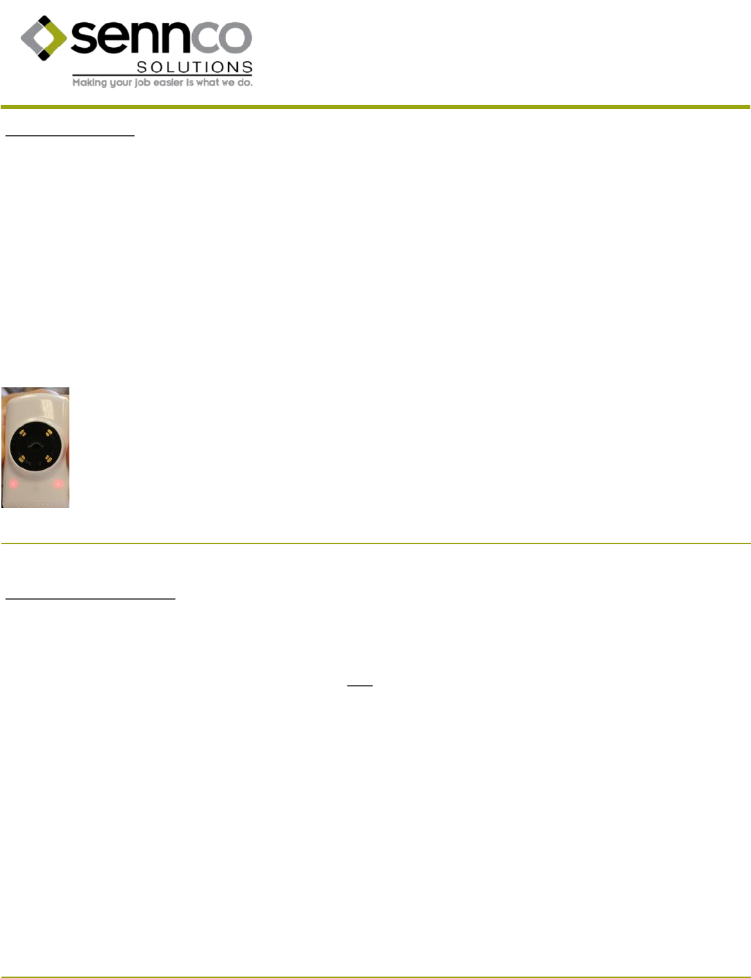
7. Place the sensor head on a powered cradle to “wake up” the sensor head.
8. Two red LEDs on the back of the sensor head will ash indicang that the sensor head is acve but not yet monitored by the system.
9. Clean the back of the device to be protected using an alcohol wipe. Dry with a clean cloth.
Cauon: DO NOT connect devices that draw more than 2A.
10. Plug the micro USB power cable (charging cable) into the charging port on the sensor head.
11. The end of the micro USB power cable is molded to t snugly in the sensor head’s charging port.
12. Peel the backing o of the sensor head adhesive.
Prepared 10/2016 18 Patent pending
14407 Coil Plus Dr, Unit A | Plaineld, IL 60544
www.sennco.com | techsupport@sennco.com
815.577.3400 | Toll free 866.736.6261
Mon - Fri 9AM - 5PM CST
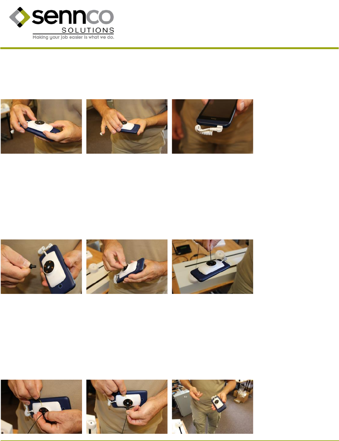
13. Center the sensor head on the back of the device to be protected.
14. Press rmly for about 15 seconds for a strong adhesive bond.
15. Plug the charging cable into the device’s charging port.
F. Connecng sensor heads to Cordwinder cables
1. Pull a length of the Cordwinder cable from the cradle and bring the sensor head to it.
2. Insert the cable end into the hole in the back of the sensor head. Then turn the cable end a quarter turn clockwise. You will hear and feel a
click when the cable is locked.
3. The cable end will sll rotate about a quarter turn but will not come out without using the tether disconnect key.
G. Disconnecng sensor heads from Cordwinder cables
1. Insert the tether disconnect key into the hole in the side of the sensor head. The key is exible to prevent damage to internal components.
2. You will feel a click when the cable end is unlocked. Turn the cable end about a quarter turn counter-clockwise and pull it out of the sensor
head.
3. The protected device is now released from the mechanical security while sll being monitored by the wireless system.
Prepared 10/2016 19 Patent pending
14407 Coil Plus Dr, Unit A | Plaineld, IL 60544
www.sennco.com | techsupport@sennco.com
815.577.3400 | Toll free 866.736.6261
Mon - Fri 9AM - 5PM CST
B. Teaching addional DaKeys
1. Insert any previously taught DaKey into the Main Alarm.
2. Remove the DaKey.
3. Within ve seconds, insert the next DaKey to be taught.
4. The system will automacally program this DaKey.
5. The LCD will state “KEY LEARNED” and the count of keys learned will be updated..
6. Remove the DaKey.
7. Note: Up to ten DaKeys can be taught to the system.
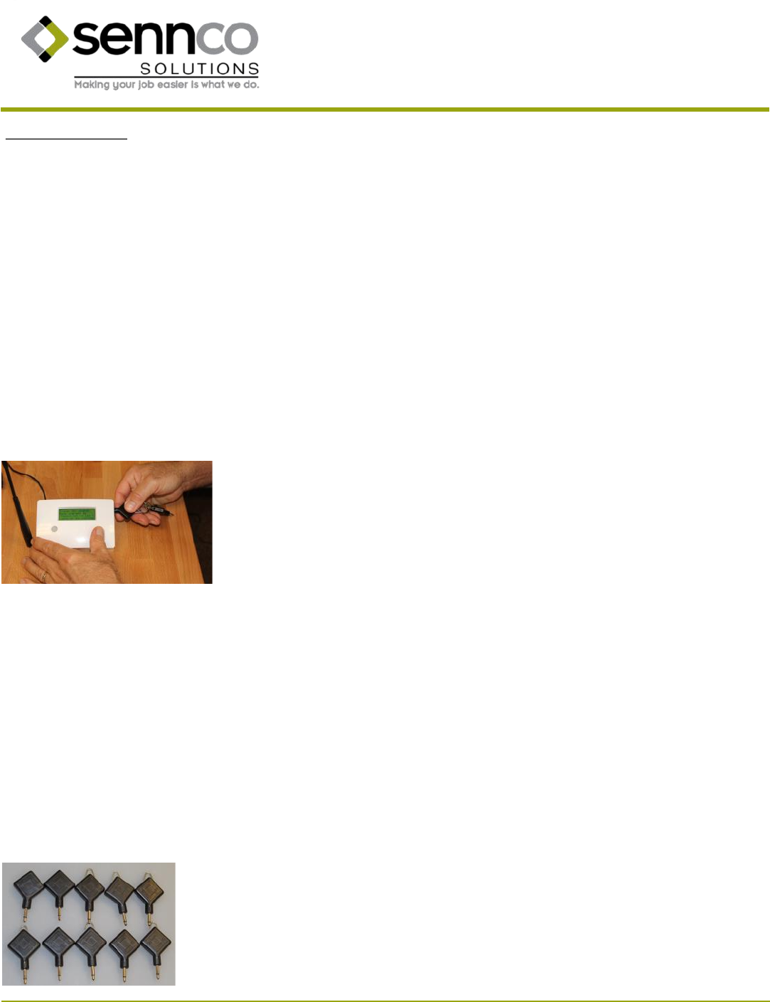
IV. Teaching DaKeys
DaKeys will be programmed or “taught” to the system simply by inserng them into the DaKey port on the Main Alarm. The rst DaKey inserted
will be taught automacally. Addional DaKeys can be taught by inserng them within ve seconds aer removing a previously taught DaKey.
Anyme a recognized DaKey is inserted and removed the system provides a ve second window of opportunity for teaching another DaKey.
A. Teaching the rst DaKey
1. Ensure the system has power supplied.
2. Insert a DaKey into the DaKey port on the Main Alarm.
3. The system will automacally program this DaKey.
4. The LCD will state “KEY LEARNED” and show the count of keys learned as 01.
5. Remove the DaKey.
Prepared 10/2016 20 Patent pending
14407 Coil Plus Dr, Unit A | Plaineld, IL 60544
www.sennco.com | techsupport@sennco.com
815.577.3400 | Toll free 866.736.6261
Mon - Fri 9AM - 5PM CST
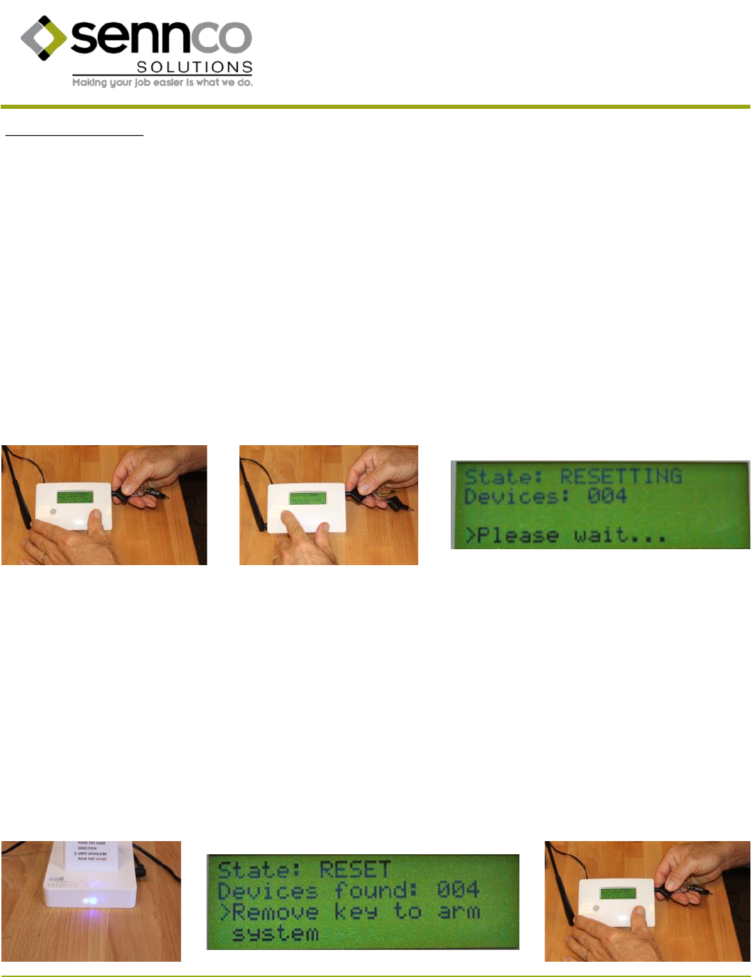
V. Reseng the system
A. Make sure that the Main Alarm has power, all Security Perimeter Domes have power (indicated by a green LED), all of the cradles have pow-
er (indicated by a red LED on the underside of the cradle), and that all of the sensor heads have been acvated by placing them on a pow-
ered cradle (indicated by two red ashing LEDs on the sensor head).
B. Make sure that the Security Perimeter Domes are spaced no more than 3 1/2 feet apart with all of their arrows pointed in the same
direcon. Make sure each cradle is within 3 feet of a Security Perimeter Dome and within 50 feet of the Main Alarm. Make sure that near-
est sensor head is at least 2 feet away from the Main Alarm.
C. Insert a recognized DaKey into the Main Alarm and leave it inserted.
D. The Security Perimeter Domes will all begin to ping a signal back to the Main Alarm (indicated by a blue ashing LED on each Security
Perimeter Dome).
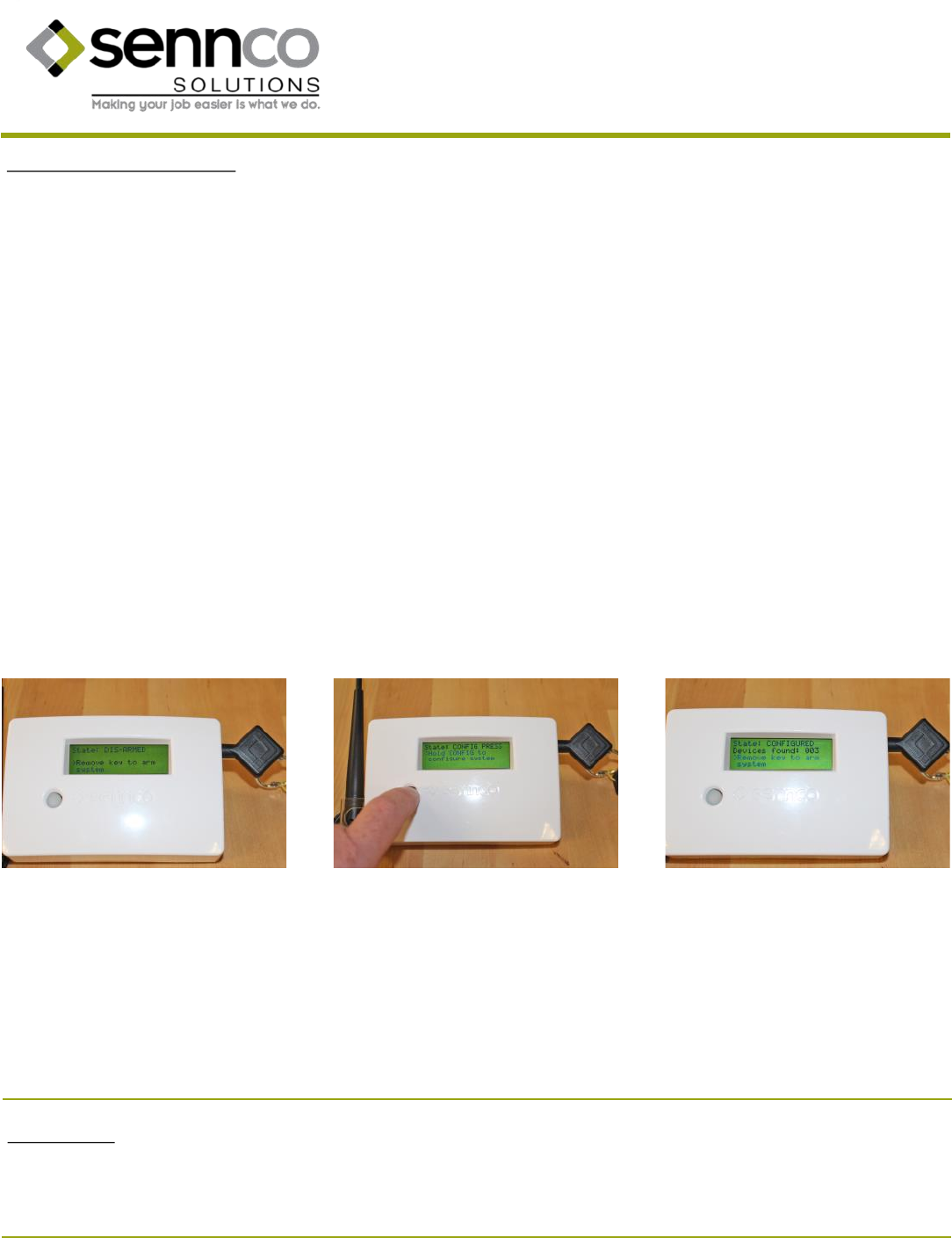
E. The LCD will state “DIS-ARMED”
F. Hold down the buon on the front of the Main Alarm unl the LCD states, “RELEASE TO RESET.” (Approximately 4 seconds)
G. The LCD will state “RESETTING” and show a device count of 000.
H. The Main Alarm will listen for all of the sensor heads and the device count on the LCD will be updated.
I. When completed, the LCD will state “RESET” and show a count of the total number of sensor heads found. If this number is less than the
physically present heads check all of them and then repeat the reset.
J. The LCD will also state “Remove key to arm the system” indicang it is now safe to remove the DaKey from the Main Alarm.. The system is
not armed unl the DaKey has been removed.
K. Aer removing the DaKey there will be a less than 5 second delay before the system is armed. The Security Perimeter Domes will ash a
blue LED and the sensor heads will ash a green LED as they ping back to the Main Alarm each second.
Prepared 10/2016 21 Patent pending
14407 Coil Plus Dr, Unit A | Plaineld, IL 60544
www.sennco.com | techsupport@sennco.com
815.577.3400 | Toll free 866.736.6261
Mon - Fri 9AM - 5PM CST
VI. Sensor head alarm
A. If the sensor head is out of the “safe zone” sphere created by the Security Perimeter Domes then the red LEDs on the sensor head will begin
to ash.
B. Aer 1-2 seconds the sensor head will emit an alarm tone that is audible to the person holding the device.
C. The ashing red LEDs and audible tone serve as a polite warning that the device needs to be brought back within the safe zone.
D. If returned to the safe zone within 5 seconds the audible tone and ashing red LEDs will cease. The sensor head will return to ashing green
LEDs indicang it is armed.
E. If, however, the device is not returned to the safe zone within 5 seconds then the Main Alarm will be triggered causing it to emit a loud
alarm that is audible throughout the area.
VII. Silencing the Main Alarm
A. If the system alarms, check the LCD on the Main Alarm. It will show which sensor head has triggered the alarm.
B. Insert a recognized DaKey into the Main Alarm to silence it. (Note: This silences the Main Alarm but does not disarm it. Any addional
alarms triggered will sll appear in the analycs data. See secon VIII for instrucons on disarming the system.)
C. Check for the issue which caused the alarm to sound.
D. Make any necessary changes (i.e. reaaching a sensor head).
E. Repeat steps in part V for reseng the system.
F. Remove the DaKey.
G. Aer a less than 5 second delay the system will resume normal operaon.
H. Technical support can be reached at 866-736-6261 (toll free), 815-557-4786 (cellular), or techsupport@sennco.com (email).
Prepared 10/2016 22 Patent pending
14407 Coil Plus Dr, Unit A | Plaineld, IL 60544
www.sennco.com | techsupport@sennco.com
815.577.3400 | Toll free 866.736.6261
Mon - Fri 9AM - 5PM CST
VIII. Disarming the Main Alarm
A. Insert DaKey in Main Alarm.
B. Press and hold buon 3 seconds to reset the system. LCD will state “Release to reset.”
C. Wait for all sensors to be found. Repeat step B if not all sensors are found.
D. LCD will state, “Remove key to arm system.” The system will remain disarmed unl the key has been removed.
E. Note: Use this procedure
1. When moving displayed device for overnight storage
(see instrucon 120-004 Genesis - Securing Product O Display While Store Closed)
2. When changing aached device
(see instrucon 120-005 Genesis - Changing Aached Product)
3. When removing sensor head(s) permanently.
(see instrucon 120-006 Genesis - Removing Sensor Head from System)
IX. Hard Reset
The enre system can be reset by inserng a recognized DaKey, unplugging power from the Main Alarm unit, and then holding down the buon
on the front of the Main Alarm for longer than 10 seconds.
Prepared 10/2016 23 Patent pending
14407 Coil Plus Dr, Unit A | Plaineld, IL 60544
www.sennco.com | techsupport@sennco.com
815.577.3400 | Toll free 866.736.6261
Mon - Fri 9AM - 5PM CST
X. Points of Sensing
B. Sensor head plunger
C. Sensor head proximity
A. Micro USB power cable
If the Micro USB power cable (charging cable) is unplugged from the protected device or from the sensor head or if it is cut, then both the Main
Alarm and the specic sensor head will immediately siren.
If the sensor head is removed from the back of the protected device then both the Main Alarm and the specic sensor head will immediately
siren.
If the sensor head is outside of the “safe zone” created by the Security Perimeter Domes for more than 5 seconds then both the Main Alarm and
the specic sensor head will immediately siren.

Prepared 10/2016 24 Patent pending
14407 Coil Plus Dr, Unit A | Plaineld, IL 60544
www.sennco.com | techsupport@sennco.com
815.577.3400 | Toll free 866.736.6261
Mon - Fri 9AM - 5PM CST
Quesons? Please contact Sennco Soluons technical support at:
Toll free phone: 866-736-6261
Cellular phone: 815-557-4786
Email: techsupport@sennco.com
COPYRIGHT © 2016 Sennco Soluons, Inc. All rights reserved.

Prepared 10/2016 25 Patent pending
14407 Coil Plus Dr, Unit A | Plaineld, IL 60544
www.sennco.com | techsupport@sennco.com
815.577.3400 | Toll free 866.736.6261
Mon - Fri 9AM - 5PM CST
This page intenonally le blank.