Sensitech T11008340 TEMPTALE RF GATEWAY/REPEATER/SIGNPOST User Manual TTRF Setup WIP new
Sensitech, INC. TEMPTALE RF GATEWAY/REPEATER/SIGNPOST TTRF Setup WIP new
UserManual.wiki
>
Sensitech
>
T11008340 User Manual
USERS MANUAL
Navigation menu
Upload a User Manual
Namespaces
Wiki Guide
HTML
PDF
Info
Views
User Manual
Discussion / Help
Navigation
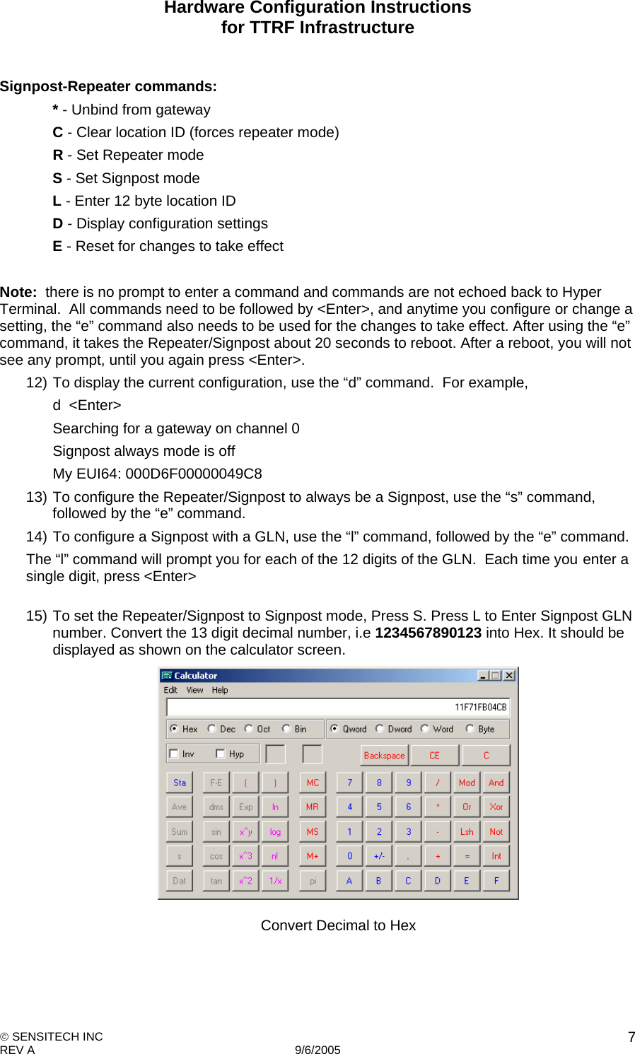
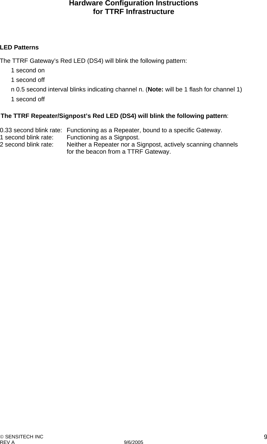
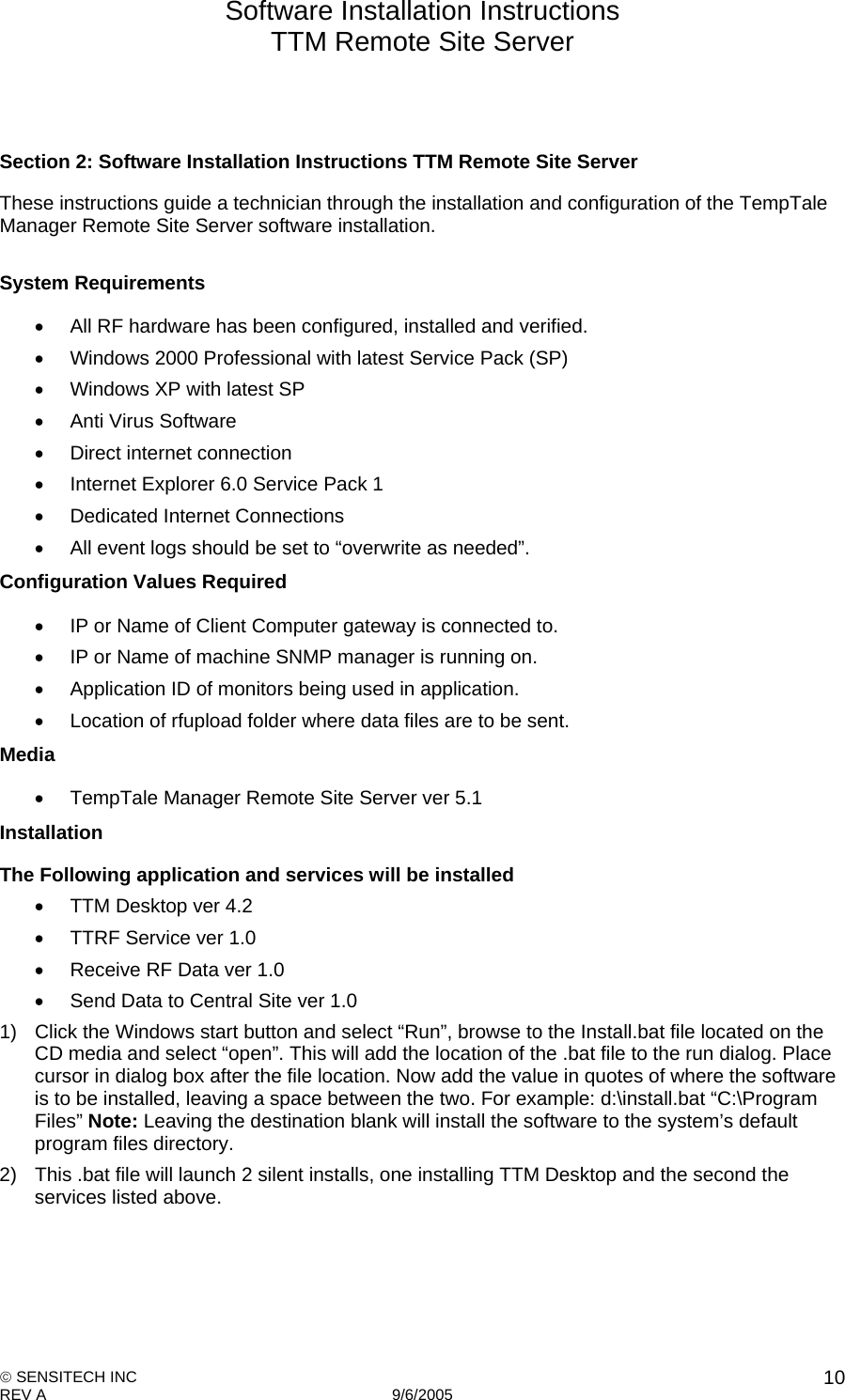
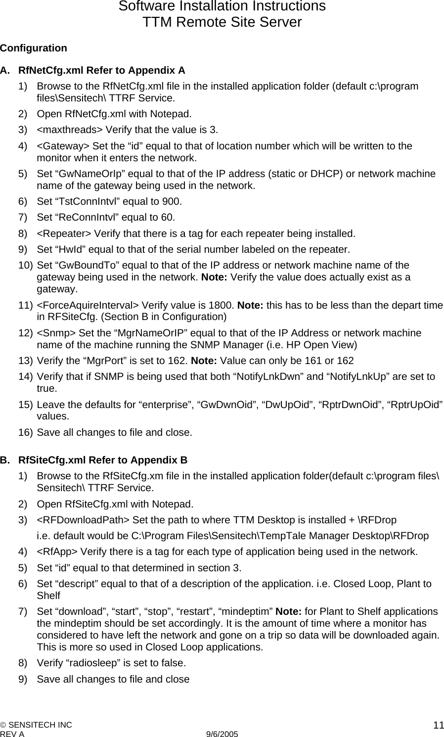
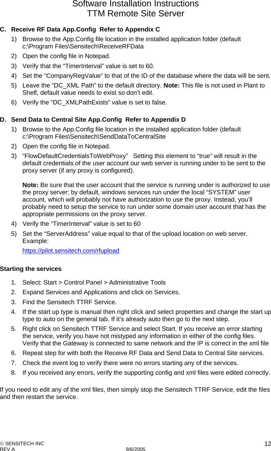
![Hardware Configuration Instructions for TTRF Infrastructure SENSITECH INC REV A 9/6/2005 8 16) Enter the Hex GLN number starting at byte [7 of 12]. The following screen should be displayed. Hex GLN Number in Hyper Terminal 17) To clear the GLN and turn the Signpost back in to a Repeater/Signpost, use the “c” command, followed by the “e” command. 18) You can also configure the Signpost to be a Repeater/Signpost, use the “r” command, followed by the “e” command. 19) Use the “*” command to unbind a Repeater that has previously been “Bound” to a specific TTRF Gateway. Note: You can also use the “Unbind” button (SW1) on the Repeater/Signpost Motherboard to unbind from a TTRF Gateway.](https://usermanual.wiki/Sensitech/T11008340/User-Guide-696552-Page-8.png)