Sensitech T11008340 TEMPTALE RF GATEWAY/REPEATER/SIGNPOST User Manual TTRF Setup WIP new
Sensitech, INC. TEMPTALE RF GATEWAY/REPEATER/SIGNPOST TTRF Setup WIP new
USERS MANUAL

SENSITECH INC
REV A 9/6/2005
1
TempTale RF
Infrastructure and Remote Site Server
Setup Instructions
Date: 8/15/2006
Revision: A
FCC Part 15, Class A Manual Statement
RF GATEWAY PN: T11008340
FCC ID: SRMT11008340
IC: 6654A-11008340
This device complies with Part 15 of the FCC Rules. Operation is subject to
the following two conditions: (1) this device may not cause harmful
interference, and (2) this device must accept any interference received,
including interference that may cause undesired operation. Changes or
modifications not expressly approved by Sensitech could void the users’
authorit
y
to o
p
erate the e
q
ui
p
ment
RADIO AND TELEVISION INTERFERENCE
NOTE: This equipment has been tested and found to comply with the
limits for a Class A digital device, pursuant to Part 15 of the FCC rules.
These limits are designed to provide reasonable protection against
harmful interference when the equipment is operated in a commercial
environment. This equipment generates, uses and can radiate radio
frequency energy and, if not installed and used in accordance with the
instruction manual, may cause harmful interference to radio
communications. Operation of this equipment in a residential area is
likely to cause harmful interference in which case the user will be
required to correct the interference at his own expense.
SENSITECH INC
REV A 9/6/2005
2
Table of Contents
TempTale® RF System................................................................................................................... 3
Section 1: Hardware Configuration Instructions for TTRF Infrastructure ........................................ 4
Equipment........................................................................................................................................ 4
Configuring the TTRF Gateway for a static IP address or DHCP agent ......................................... 4
Configure the Repeater/Signpost with a GLN and set Modes ........................................................ 6
Signpost-Repeater commands........................................................................................................ 7
LED Patterns ................................................................................................................................... 9
Section 2: Software Installation Instructions TTM Remote Site Server......................................... 10
System Requirements ................................................................................................................... 10
Configuration Values Required...................................................................................................... 10
Media............................................................................................................................................. 10
Installation...................................................................................................................................... 10
Configuration ................................................................................................................................. 11
Starting the services ...................................................................................................................... 12
Appendix A RfNetCfg.xml............................................................................................................. 13
Appendix B RfSiteCfg.xml ............................................................................................................. 14
Appendix B RfSiteCfg.xml ............................................................................................................. 14
Appendix C ReceiveRFData.exe.config. xml ................................................................................ 15
Appendix D SendDataToCentralSite.xml ...................................................................................... 15

Hardware Configuration Instructions
for TTRF Infrastructure
SENSITECH INC
REV A 9/6/2005
3
TempTale® RF System
The TempTale® RF system uses software and hardware to capture temperature data and
download the data wirelessly to a local computer. The data is then sent via Internet to a secure
database where the data can be viewed and analyzed. The software is Remote Site Server
(RSS) and the hardware is; TempTale RF monitors (TTRF) and three other types of RF (Radio
Frequency) devices:
Gateways - are RF monitor readers attached via Ethernet to the PC running RSS
Repeaters - extend the area covered by the network.
Signposts - transmit a location ID which is stored in the monitors.
Depending on geographic region, the TTRF system operates within two ISM (Industrial, Scientific
and Medicine) frequency bands:
870.0 MHz in Europe and
928 MHz in North America
Within these bands, the TTRF System uses specific channels to transmit and receive data. For
the 902 - 928 MHz band the following channels are used:
914.904 MHz
922.277 MHz
For the 869 MHz band the following channel is used:
869.850 MHz
The RF signal used is a narrow band transmission that transmits power at +2 dBm for the
monitors and 0dBm for the Infrastructure (Gateway, Repeaters and Signposts). Both the monitor
and Infrastructure devices have an ERP (Effective Radiated Power) of about 2dB below the FCC
limit of 94 dB µV/m. The channel width is 185 kHz, with 99% of energy within this channel. For
US TTRF systems, the RF infrastructure (Gateways, Repeaters and Signposts) will be set to one
of the two channels based on the current S/N (Signal to Noise) ratio of all the available channels
at the time the system is installed at a customer site. The operating channel can be manually
changed at any time if there is too much noise (i.e. interference) on the current channel1.
US operating TTRF systems (using the 902 – 928 MHz ISM band) conform to FCC rule Part 15,
Section 249, which states:
The field strength of emissions from intentional radiators operated within these frequency bands
shall comply with the following:·
Fundamental Frequency field strength: 50 millivolts/meter·
Harmonics Frequency field strength: 500 microvolts/meter
1 For European operations, there is currently only one channel to use for the TTRF system.
Hardware Configuration Instructions
for TTRF Infrastructure
SENSITECH INC
REV A 9/6/2005
4
Section 1: Hardware Configuration Instructions for TTRF Infrastructure
These instructions guide a technician through the installation and configuration of the TempTale
RF infrastructure.
Equipment
RS232 Serial cable (1)
TTL Converter (1)
RJ45 Ethernet crossover-cable (1)
TTRF Gateway (1)
Repeater (1)
Gateway Power Adaptor (1)
Repeater Power Adaptor (1)
PC with Start Hyper Terminal installed
PC with scientific calculator
Ethernet connection
Configuring the TTRF Gateway for a static IP address or DHCP agent
Gateway2
1) Make sure power is off on the TTRF Gateway.
2 Repeater/Signposts use the same Motherboard.
Hardware Configuration Instructions
for TTRF Infrastructure
SENSITECH INC
REV A 9/6/2005
5
2) Open up the front panel of the TTRF Gateway and connect the TTL Converter to the
female DB9 Admin Port on the Motherboard.
3) Make sure the connector on Jumper J4 is present (attached) on the Motherboard.
4) Connect the Sensitech RS232 Serial cable from the TTL Converter to the COM1 port on
the Control PC.
5) Make sure the RJ45 Ethernet cable coming from the Daughter Board is NOT connected
to the Customer’s Ethernet Network.
6) Power on the TTRF Gateway.
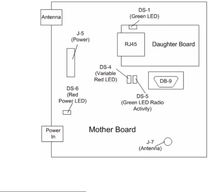
7) Verify TTRF Gateway LED light patterns:
Constant Red PWR Indicator LED on the Motherboard (DS6)
Variable blinking Red LED on mother board (DS4)
Possibly a variable blinking Green “Radio Activity” LED on mother board (DS5)
Possibly a constant Green LED (DS1) on the Daughter Board, if the RJ45 cable
is connected to an active Ethernet network drop.
8) Start Hyper Terminal on the PC from Start/All Programs/Accessories/Communications.
9) Create a new Hyper Terminal Name (i.e. gateway), then press OK.
10) In the “Connect using” dropdown select COM1, then press OK.
11) Set values to: Bits per second =19200, Data bits= 8, Parity= none, Stop bits =1, Flow
control =none, then press OK.
12) Position the cursor in the popup Hyper Terminal window, and press Enter a few times
until you get an Ember> prompt. It might take a few seconds to come up.
13) At the Ember prompt use the “config” command to see the current gateway values:
Ember> config
14) If using a static IP address for the TTRF Gateway, you must first set the DHCP value to
off:
Ember> ip_dhcp off
15) To set a static IP address, use the “static_ip” command:
Ember> ip_static <ipaddress> <netmask> <gateway>
Where: <ipaddress> is the IP address
<netmask> is the subnet mask
<gateway> is the default gateway on the subnet
Example:
Ember> ip_static 172.16.7.234 255.255.255.0 172.16.7.1
16) Type config again at the Ember prompt to verify the IP static information is correct.
17) If you are using a DHCP server, first set the DHCP value to on:
Ember> ip_dhcp on
18) To set the DHCP hostname of the TTRF Gateway, use the “hostname set” command:
Ember> hostname set <name>
Where <name> is the DHCP hostname of the TTRF Gateway (20 characters or
less).
Hardware Configuration Instructions
for TTRF Infrastructure
SENSITECH INC
REV A 9/6/2005
6
Note: For the DHCP settings to take effect, the TTRF Gateway has to have its
power recycled.
19) To read the current DHCP hostname set in the TTRF Gateway, use the “hostname read”
command:
Ember> hostname read
20) For a list of commands, enter:
Ember> ?
21) For help on a specific command, enter, “?” followed by the command name. Example:
Ember> ? ip_static
22) Make note of the Gateway’s IP configuration values since they will need to be entered
into configuration files on the RF Control PC and, if using DHCP, the hostname will need
to be listed on the DHCP server.
23) Turn off power to the TTRF Gateway and connect the RJ45 Ethernet cable from the
TTRF Gateway “Daughter Board” to the Customer’s Network drop.
24) Power on the TTRF Gateway.
25) Verify the TTRF Gateway LED light patterns, as described in step 6 above.
26) Verify you can ping the Gateway IP from the PC or any other computer on the same
subnet.
Configure the Repeater/Signpost with a GLN and set Modes
1) Make sure power is off on the TTRF Repeater/Signpost.
2) Open up the front panel of the TTRF Repeater/Signpost and attach the Serial-10 pin
cable to the 10 pin connector on the Motherboard (SP1). Make sure the red colored
side of the cable is aligned with the “o” on the Motherboard.
3) Attach the TTL Converter to the Serial-10pin cable.
4) Connect the Serial RS232 cable from the TTL Converter to the COM1 port on the Control
PC.
5) Power on the TTRF Repeater/Signpost.
6) Verify LED light patterns:
Constant Red PWR Indicator LED on the Motherboard (DS6)
Variable blinking Red LED on Motherboard (DS4)
Possibly a variable blinking Green “Radio Activity” LED on mother board (DS5)
7) Start Hyper Terminal on the PC from Start/All Programs/Accessories/Communications.
8) Create a new Hyper Terminal Name (i.e. repeater), then press OK.
9) In the “Connect using” dropdown select COM1, then press OK.
10) Set values to: Bits per second =19200, Data bits= 8, Parity= none, Stop bits =1, Flow
control =none, then press OK.
11) Position the cursor in the popup Hyper Terminal window, and press Enter a few times
until you see the following list of commands appear: (Note: It might take a few seconds
to come up).
Hardware Configuration Instructions
for TTRF Infrastructure
SENSITECH INC
REV A 9/6/2005
7
Signpost-Repeater commands:
* - Unbind from gateway
C - Clear location ID (forces repeater mode)
R - Set Repeater mode
S - Set Signpost mode
L - Enter 12 byte location ID
D - Display configuration settings
E - Reset for changes to take effect
Note: there is no prompt to enter a command and commands are not echoed back to Hyper
Terminal. All commands need to be followed by <Enter>, and anytime you configure or change a
setting, the “e” command also needs to be used for the changes to take effect. After using the “e”
command, it takes the Repeater/Signpost about 20 seconds to reboot. After a reboot, you will not
see any prompt, until you again press <Enter>.
12) To display the current configuration, use the “d” command. For example,
d <Enter>
Searching for a gateway on channel 0
Signpost always mode is off
My EUI64: 000D6F00000049C8
13) To configure the Repeater/Signpost to always be a Signpost, use the “s” command,
followed by the “e” command.
14) To configure a Signpost with a GLN, use the “l” command, followed by the “e” command.
The “l” command will prompt you for each of the 12 digits of the GLN. Each time you enter a
single digit, press <Enter>
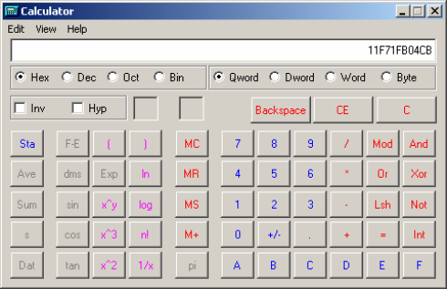
15) To set the Repeater/Signpost to Signpost mode, Press S. Press L to Enter Signpost GLN
number. Convert the 13 digit decimal number, i.e 1234567890123 into Hex. It should be
displayed as shown on the calculator screen.
Convert Decimal to Hex

Hardware Configuration Instructions
for TTRF Infrastructure
SENSITECH INC
REV A 9/6/2005
8
16) Enter the Hex GLN number starting at byte [7 of 12]. The following screen should be
displayed.
Hex GLN Number in Hyper Terminal
17) To clear the GLN and turn the Signpost back in to a Repeater/Signpost, use the “c”
command, followed by the “e” command.
18) You can also configure the Signpost to be a Repeater/Signpost, use the “r” command,
followed by the “e” command.
19) Use the “*” command to unbind a Repeater that has previously been “Bound” to a specific
TTRF Gateway. Note: You can also use the “Unbind” button (SW1) on the
Repeater/Signpost Motherboard to unbind from a TTRF Gateway.
Hardware Configuration Instructions
for TTRF Infrastructure
SENSITECH INC
REV A 9/6/2005
9
LED Patterns
The TTRF Gateway’s Red LED (DS4) will blink the following pattern:
1 second on
1 second off
n 0.5 second interval blinks indicating channel n. (Note: will be 1 flash for channel 1)
1 second off
The TTRF Repeater/Signpost’s Red LED (DS4) will blink the following pattern:
0.33 second blink rate: Functioning as a Repeater, bound to a specific Gateway.
1 second blink rate: Functioning as a Signpost.
2 second blink rate: Neither a Repeater nor a Signpost, actively scanning channels
for the beacon from a TTRF Gateway.
Software Installation Instructions
TTM Remote Site Server
SENSITECH INC
REV A 9/6/2005
10
Section 2: Software Installation Instructions TTM Remote Site Server
These instructions guide a technician through the installation and configuration of the TempTale
Manager Remote Site Server software installation.
System Requirements
All RF hardware has been configured, installed and verified.
Windows 2000 Professional with latest Service Pack (SP)
Windows XP with latest SP
Anti Virus Software
Direct internet connection
Internet Explorer 6.0 Service Pack 1
Dedicated Internet Connections
All event logs should be set to “overwrite as needed”.
Configuration Values Required
IP or Name of Client Computer gateway is connected to.
IP or Name of machine SNMP manager is running on.
Application ID of monitors being used in application.
Location of rfupload folder where data files are to be sent.
Media
TempTale Manager Remote Site Server ver 5.1
Installation
The Following application and services will be installed
TTM Desktop ver 4.2
TTRF Service ver 1.0
Receive RF Data ver 1.0
Send Data to Central Site ver 1.0
1) Click the Windows start button and select “Run”, browse to the Install.bat file located on the
CD media and select “open”. This will add the location of the .bat file to the run dialog. Place
cursor in dialog box after the file location. Now add the value in quotes of where the software
is to be installed, leaving a space between the two. For example: d:\install.bat “C:\Program
Files” Note: Leaving the destination blank will install the software to the system’s default
program files directory.
2) This .bat file will launch 2 silent installs, one installing TTM Desktop and the second the
services listed above.
Software Installation Instructions
TTM Remote Site Server
SENSITECH INC
REV A 9/6/2005
11
Configuration
A. RfNetCfg.xml Refer to Appendix A
1) Browse to the RfNetCfg.xml file in the installed application folder (default c:\program
files\Sensitech\ TTRF Service.
2) Open RfNetCfg.xml with Notepad.
3) <maxthreads> Verify that the value is 3.
4) <Gateway> Set the “id” equal to that of location number which will be written to the
monitor when it enters the network.
5) Set “GwNameOrIp” equal to that of the IP address (static or DHCP) or network machine
name of the gateway being used in the network.
6) Set “TstConnIntvl” equal to 900.
7) Set “ReConnIntvl” equal to 60.
8) <Repeater> Verify that there is a tag for each repeater being installed.
9) Set “HwId” equal to that of the serial number labeled on the repeater.
10) Set “GwBoundTo” equal to that of the IP address or network machine name of the
gateway being used in the network. Note: Verify the value does actually exist as a
gateway.
11) <ForceAquireInterval> Verify value is 1800. Note: this has to be less than the depart time
in RFSiteCfg. (Section B in Configuration)
12) <Snmp> Set the “MgrNameOrIP” equal to that of the IP Address or network machine
name of the machine running the SNMP Manager (i.e. HP Open View)
13) Verify the “MgrPort” is set to 162. Note: Value can only be 161 or 162
14) Verify that if SNMP is being used that both “NotifyLnkDwn” and “NotifyLnkUp” are set to
true.
15) Leave the defaults for “enterprise”, “GwDwnOid”, “DwUpOid”, “RptrDwnOid”, “RptrUpOid”
values.
16) Save all changes to file and close.
B. RfSiteCfg.xml Refer to Appendix B
1) Browse to the RfSiteCfg.xm file in the installed application folder(default c:\program files\
Sensitech\ TTRF Service.
2) Open RfSiteCfg.xml with Notepad.
3) <RFDownloadPath> Set the path to where TTM Desktop is installed + \RFDrop
i.e. default would be C:\Program Files\Sensitech\TempTale Manager Desktop\RFDrop
4) <RfApp> Verify there is a tag for each type of application being used in the network.
5) Set “id” equal to that determined in section 3.
6) Set “descript” equal to that of a description of the application. i.e. Closed Loop, Plant to
Shelf
7) Set “download”, “start”, “stop”, “restart”, “mindeptim” Note: for Plant to Shelf applications
the mindeptim should be set accordingly. It is the amount of time where a monitor has
considered to have left the network and gone on a trip so data will be downloaded again.
This is more so used in Closed Loop applications.
8) Verify “radiosleep” is set to false.
9) Save all changes to file and close

Software Installation Instructions
TTM Remote Site Server
SENSITECH INC
REV A 9/6/2005
12
C. Receive RF Data App.Config Refer to Appendix C
1) Browse to the App.Config file location in the installed application folder (default
c:\Program Files\Sensitech\ReceiveRFData
2) Open the config file in Notepad.
3) Verify that the “TimerInterval” value is set to 60.
4) Set the “CompanyRegValue” to that of the ID of the database where the data will be sent.
5) Leave the “DC_XML Path” to the default directory. Note: This file is not used in Plant to
Shelf, default value needs to exist so don’t edit.
6) Verify the “DC_XMLPathExists” value is set to false.
D. Send Data to Central Site App.Config Refer to Appendix D
1) Browse to the App.Config file location in the installed application folder (default
c:\Program Files\Sensitech\SendDataToCentralSite
2) Open the config file in Notepad.
3) “FlowDefaultCredentialsToWebProxy” Setting this element to “true” will result in the
default credentials of the user account our web server is running under to be sent to the
proxy server (if any proxy is configured).
Note: Be sure that the user account that the service is running under is authorized to use
the proxy server: by default, windows services run under the local “SYSTEM” user
account, which will probably not have authorization to use the proxy. Instead, you’ll
probably need to setup the service to run under some domain user account that has the
appropriate permissions on the proxy server.
4) Verify the “TimerInterval” value is set to 60
5) Set the “ServerAddress” value equal to that of the upload location on web server.
Example:
https://pilot.sensitech.com/rfupload
Starting the services
1. Select: Start > Control Panel > Administrative Tools
2. Expand Services and Applications and click on Services.
3. Find the Sensitech TTRF Service.
4. If the start up type is manual then right click and select properties and change the start up
type to auto on the general tab. If it’s already auto then go to the next step.
5. Right click on Sensitech TTRF Service and select Start. If you receive an error starting
the service, verify you have not mistyped any information in either of the config files.
Verify that the Gateway is connected to same network and the IP is correct in the xml file
6. Repeat step for with both the Receive RF Data and Send Data to Central Site services.
7. Check the event log to verify there were no errors starting any of the services.
8. If you received any errors, verify the supporting config and xml files were edited correctly.
If you need to edit any of the xml files, then simply stop the Sensitech TTRF Service, edit the files
and then restart the service.
Software Installation Instructions
TTM Remote Site Server
SENSITECH INC
REV A 9/6/2005
13
Appendix A RfNetCfg.xml
<RfNetCfg>
<maxthreads>3</maxthreads>
- <!-- max number of monitors to be dowloaded at a time-->
- <!-- Gateway id upto 12 digits must be numeric this is the location id
transmitted to the omegarfs -->
- <!-- Gateway GwNameOrIP IP address or machine name of gateway -->
- <!-- Gateway TstConnIntvl interval in seconds to check gateway
connection -->
- <!-- Gateway ReConnIntvl interval in seconds to retry connection to
gateway -->
- <!-- Gateway id="1965" GwNameOrIP="172.16.24.92" TstConnIntvl="900"
ReConnIntvl="60" -->
<Gateway id="1965" GwNameOrIP="192.168.1.92" TstConnIntvl="900"
ReConnIntvl="60" />
<Repeater HwId="3781220487940567" GwBoundTo="192.168.1.92" />
<Repeater HwId="3781220487940339" GwBoundTo="192.168.1.92" />
<ForceAcquireInterval>1800</ForceAcquireInterval>
- <!-- Interval in seconds to reacquire all omegarfs -->
<Snmp MgrNameOrIP="192.168.1.47" MgrPort="162" NotifyLnkDwn="true"
NotifyLnkUp="true" enterprise="1.3.6.1.4.1.23684.6.1.0"
GwDwnOid="1.3.6.1.4.1.23684.6.1.0.5.0" GwUpOid="1.3.6.1.4.1.23684.6.1.0.6.0"
RptrDwnOid="1.3.6.1.4.1.23684.6.1.0.7.0"
RptrUpOid="1.3.6.1.4.1.23684.6.1.0.8.0" />
</RfNetCfg>
Software Installation Instructions
TTM Remote Site Server
SENSITECH INC
REV A 9/6/2005
14
Appendix B RfSiteCfg.xml
<RfSiteCfg>
<RfDownloadPath> C:\Program Files\Sensitech\TempTale Manager Desktop\RFDrop
</RfDownloadPath>
- <!-- path to which temptalerf files are automatically downloaded to -->
- <!-- the following are the definition for the RFApp attributes-->
- <!-- id is the application id programmed into the monitor to tell the
control software what is to be done with the monitor -->
- <!-- descript is not currently put in to describe the application being
executed -->
- <!-- download,true to download monitor, false won't -->
- <!-- start, true to start monitor, false won't -->
- <!-- stop, true to stop monitor, false won't -->
- <!-- restart, reactivates monitor current config and start it, false
won't -->
- <!-- mindeptim, in seconds the time inwhich we decide a monitor has left
for a valid trip -->
- <!-- radiosleep, true to put radio to sleep, will not wake til it see a
different network,false won't -->
<RfApp id="0" descript="InBound Transit" download="true" start="false" stop="false"
restart="false" mindeptim="200" radiosleep="false" />
<RfApp id="1" descript="Closed Loop" download="true" start="false" stop="false"
restart="false" mindeptim="200" radiosleep="false" />
<RfApp id="2" descript="Plant to Shelf" download="true" start="false" stop="false"
restart="false" mindeptim="200" radiosleep="false" />
</RfSiteCfg>

Software Installation Instructions
TTM Remote Site Server
SENSITECH INC
REV A 9/6/2005
15
Appendix C ReceiveRFData.exe.config. xml
<?xml version="1.0" encoding="utf-8" ?>
- <?xml version="1.0" encoding="utf-8" ?>
<configuration>
<appSettings>
<add key="TimerInterval" value="60" /> <!-- seconds -->
<add key="CompanyRegValue" value=" 16839586920" /> <!--
registration value to map to customer database -->
<add key="DC_XMLPath" value="c:\DC_Configuration.xml" /> <!--
location of customer config file -->
<add key="DC_XMLPathExists" value="false" /> <!-- will there be
a customer config file-->
</appSettings>
</configuration>
Appendix D SendDataToCentralSite.xml
<?xml version="1.0" encoding="utf-8" ?>
<configuration>
<appSettings>
<add key="FlowDefaultCredentialsToWebProxy" value="false" />
<add key="TimerInterval" value="60" /><!-- seconds -->
<add key="ServerAddress"
value="https://reg.sensitechdms.com/rfpload/default.aspx" /> <!--
location of where to send files -->
</appSettings>
</configuration>
2006 Sensitech Inc. The Cold Chain Company. All rights reserved.
TempTale, Ryan, TripStrip and TagAlert are registered trademarks and Cold Chain Manager, TempTale Manager and
QuickCheck are trademarks of Sensitech Inc. All other product names and trademarks used in this document are the
property of their respective companies.