Sensium Healthcare TZ202020R1 Wireless Patient Monitoring Device - SensiumBridge User Manual TZ202000 IFU
Toumaz US Wireless Patient Monitoring Device - SensiumBridge TZ202000 IFU
Manual

SensiumVitals Wireless Monitoring
System
User Manual
Part Number: TZ202000-IFU
Toumaz and the
Toumaz logo are
trademarks or
registered trademarks
of Toumaz or one of its
subsidiaries.
All other trademarks are
the property of their
respective owners.
Toumaz US LLC
Los Angeles, CA
USA
www.toumaz.com
© 2012
Toumaz US LLC or one
of its subsidiaries.
All rights reserved.
SensiumVitals Wireless Monitoring System
Directions for Use
Changes in equipment, software, or procedures occur periodically;
information describing these changes will be included in future editions of the
guide.
The information in this document is subject to change and does not represent
a commitment on the part of Toumaz to provide additional services or
enhancements.

TZ202000-IFU Wireless Monitoring System Directions for Use
iii
Contents
About This Guide.................................................................v
Chapter 1—General Information
Intended
Use...........................................................................................................
1
Heart rate monitoring
.....................................................................................
1
Respiratory rate
monitoring............................................................................
1
Axillary temperature
monitoring
....................................................................
2
Monitoring symbols
...............................................................................................
2
General warnings and
cautions...............................................................................
3
Safety and compliance
information
................................................................
4
System information
................................................................................................
4
System
components
........................................................................................
4
Patch
components
...........................................................................................
5
Wireless Monitoring Application
screens ......................................................
6
Main
screen
..........................................................................................
6
Patient History screen
..........................................................................
8
Chapter 2—Using the SensiumVitals Wireless Monitoring
System
Logging in and out
.................................................................................................
9
Starting patient
monitoring...................................................................................
10
Required
equipment......................................................................................
10
Applying the patch
.......................................................................................
10
Adding patient to wireless
monitoring .........................................................
14
Monitoring patients
..............................................................................................
17
Editing patient settings and vital sign
limits.................................................
17
Notifications .................................................................................................
18
Receiving notifications
......................................................................
18
Acknowledging
Notifications ............................................................
18
Reminder
notifications
.......................................................................
19
Escalation
notifications
......................................................................
20
Replacing a
Patch
.................................................................................................
20
Updating patch information in the Wireless Monitoring
Application..........
20

iv
TZ202000-IFU Wireless Monitoring System Directions for Use
Contents
Removing a patient from wireless
monitor
i
ng
.....................................................
21
Running a Clinical Data Report
...........................................................................
22
Assigning beds to groups
.....................................................................................
23
Chapter 3—Troubleshooting
Logging in and out
...............................................................................................
25
Adding a patient
...................................................................................................
25
Monitoring a patient
.............................................................................................
26
Patient
History
......................................................................................................
29
Removing patients from Wireless
Monitoring
.....................................................
29
General application questions
..............................................................................
29
Notification
questions...........................................................................................
30
Error message
questions
.......................................................................................
30
Appendix A—Technical Specifications
Performance
specifications...................................................................................
31
Patch
specifications
..............................................................................................
31
Appendix B—Compliance and Safety Info
FCC compliance statement (United
States)..........................................................
33
Safety
....................................................................................................................
34
FCC Radiation Exposure
Statement
.............................................................
34
Electromagnetic compatibility
.............................................................................
35
TZ202000-IFU Wireless Monitoring System Directions for Use
v
About This Guide
This guide describes the Toumaz SensiumVitals Wireless Monitoring System
and provides instructions for wireless monitoring of patients.
The SensiumVitals Wireless Monitoring System is used to monitor a patient’s
vital signs, including heart rate, respiratory rate, and axillary temperature.
Symbols
This document uses the following symbols:
Warnings indicate potentially hazardous situations which, if not avoided,
could result in injury or death.
Caution indicates conditions that could damage equipment or other
property.
Notes contain supplementary information or emphasize a point or
procedure.

vi
TZ202000-IFU Wireless Monitoring System Directions for Use
About This Guide

TZ202000-IFU Wireless Monitoring System Directions for Use
1
Chapter
1
General Information
Intended Use
The SensiumVitals Wireless Monitoring System is intended for use by health care
professionals for routine surveillance of patient physiological parameters in a
healthcare setting. Data is transmitted wirelessly to a central location. Alerts can
be set on an individual patient basis to inform healthcare professionals when
vital sign readings are measured outside of preset limits.
The device is not intended to be used in the ICU or CCU and is intended to
supplement vital signs monitoring by healthcare professionals, not to replace it.
The device is intended for use on general care patients and on patients who are
18 years of age or older.
Heart rate monitoring
• Uses ECG to detect the heart rate (HR) only;
• Cannot be used to detect the absence of a heart rate;
• Provides intermittent HR readings in a range of 30–200 beats per minute
(BPM) when conditions are appropriate;
• Cannot be used to detect any forms of arrhythmia or any other
conditions usually detected through an ECG.
Respiratory rate monitoring
• Uses impedance pneumography to detect respiratory rate (RR);
• Provides intermittent RR readings in a range of 5–60 breaths per minute
(BrPM);
Due to the nature of impedance pneumography, it is possible that RR
readings often appear as not available. This situation is more likely to
happen when the patient is moving.
2
TZ202000-IFU Wireless Monitoring System Directions for Use
Chapter 1—General Information
Axillary temperature monitoring
• Measures the axillary temperature using a probe underneath the axilla;
• Provides intermittent axillary temperature readings in a range of 89.6 to
111.2°F;
• Due to the dependence on the patient’s proper arm position, it is possible
that axillary temperature sometimes appears as unavailable;
• Cannot be used to detect rapid drops of core body temperature.
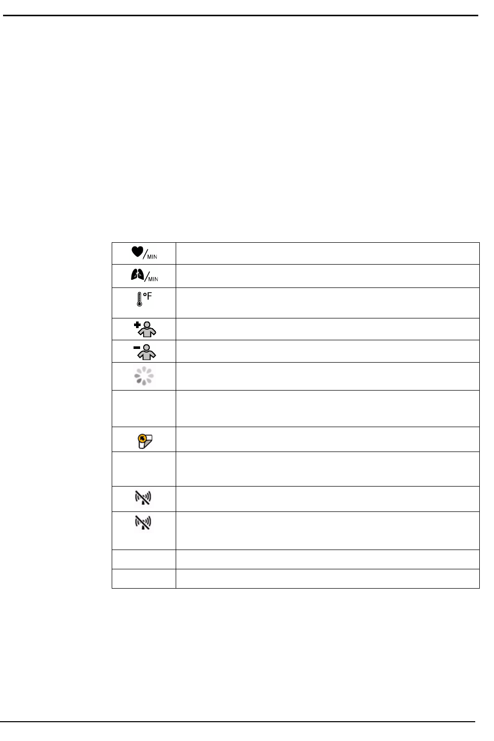
Monitoring symbols
The following symbols may appear in the Wireless Monitoring Application.
Heart Rate
(in
beats
per minute)
Respiratory Rate
(in
breaths
per minute)
Axillary Temperature
(in
degrees Fahrenheit
or
Celsius, depending
on
your
configuration)
Add Patient
to
Wireless
Monitoring
Remove patient from Wireless
Monitoring
System
is
processing information. Please
wait.
(Blinking)
Notification
Replace
Patch
(Blinking)
Replace Patch
Now
Patch
Out of Range
(Blinking)
Signal Lost (patch
out of
range
for
longer
than
specified
time)
??
Invalid
Data
--
Data
Unavailable
TZ202000-IFU Wireless Monitoring System Directions for Use
3
General warnings and cautions
General warnings and cautions
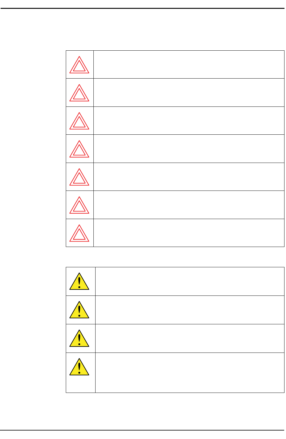
General warnings
WARNING—Do not use the SensiumVitals Wireless
Monitoring system on critical care patients.
WARNING—Remove patch before defibrillating the patient.
WARNING—The system is not designed for use with
pacemakers, implantable defibrillators, or neurostimulators.
WARNING—The system is not designed for use near magnetic
resonance imaging (MRI) equipment. Patch must be removed
from any patient about to undergo an MRI.
WARNING—The patch is not designed for use on patients under
the age of 18.
WARNING—Do not apply the patch on breached or compromised
skin surfaces or on mucosal membranes.
WARNING—The patch is a single-use device. After the patch is
removed from a patient, do not reuse the patch, whether on the
same patient or on a different patient.
General Cautions
CAUTION—The patch is a radio frequency (RF) emission device
and should not be used in RF sensitive areas.
CAUTION—The system is not designed for direct X-ray
exposure. Patch must be removed from any patient about to
undergo an upper torso X-ray.
CAUTION—The system is not designed for use near X-ray
computed tomography (CT) equipment. Patch must be removed
from any patient about to undergo a CT scan.
CAUTION—The patch is designed to be shower-proof, but vital
sign readings may be temporarily unavailable during a shower
depending on the condition of the ECG electrodes used.
It is not designed to be immersed in water or any other liquid.
4
TZ202000-IFU Wireless Monitoring System Directions for Use
Chapter 1—General Information
Safety and compliance information
This device has been designed for compliance with applicable Safety and
Electromagnetic Compatibility (IEC & FCC) regulations. See FCC compliance
statement (United States) on page 33.
System information
This section describes the system components, patch components, and the
main screens of the Wireless Monitoring Application.
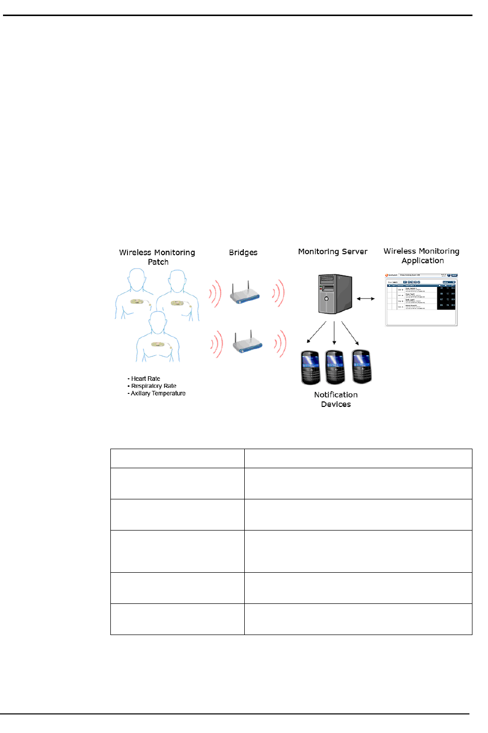
System components
System components and descriptions are provided in the following graphic
and table.
System component descriptions
Item
Description
SensiumVitals Wireless
Monitoring
Patch
Collects and transmits vital sign data from patients
to the system.
Bridges
Sends
the
vital
sign
data from each patch
to the
Monitoring
Server.
Monitoring
Server
Provides
a
link between
the
bridges and
the
Wireless Monitoring Application. Manages vital sign
data
and notifications.
Wireless
Monitoring
Application
Displays vital sign data and notifications.
Caregivers
can use it to
access system
features.
Notification
devices
Pager, PDA,
or
other device—used
to receive
and
display
notifications.
TZ202000-IFU Wireless Monitoring System Directions for Use
5
System information
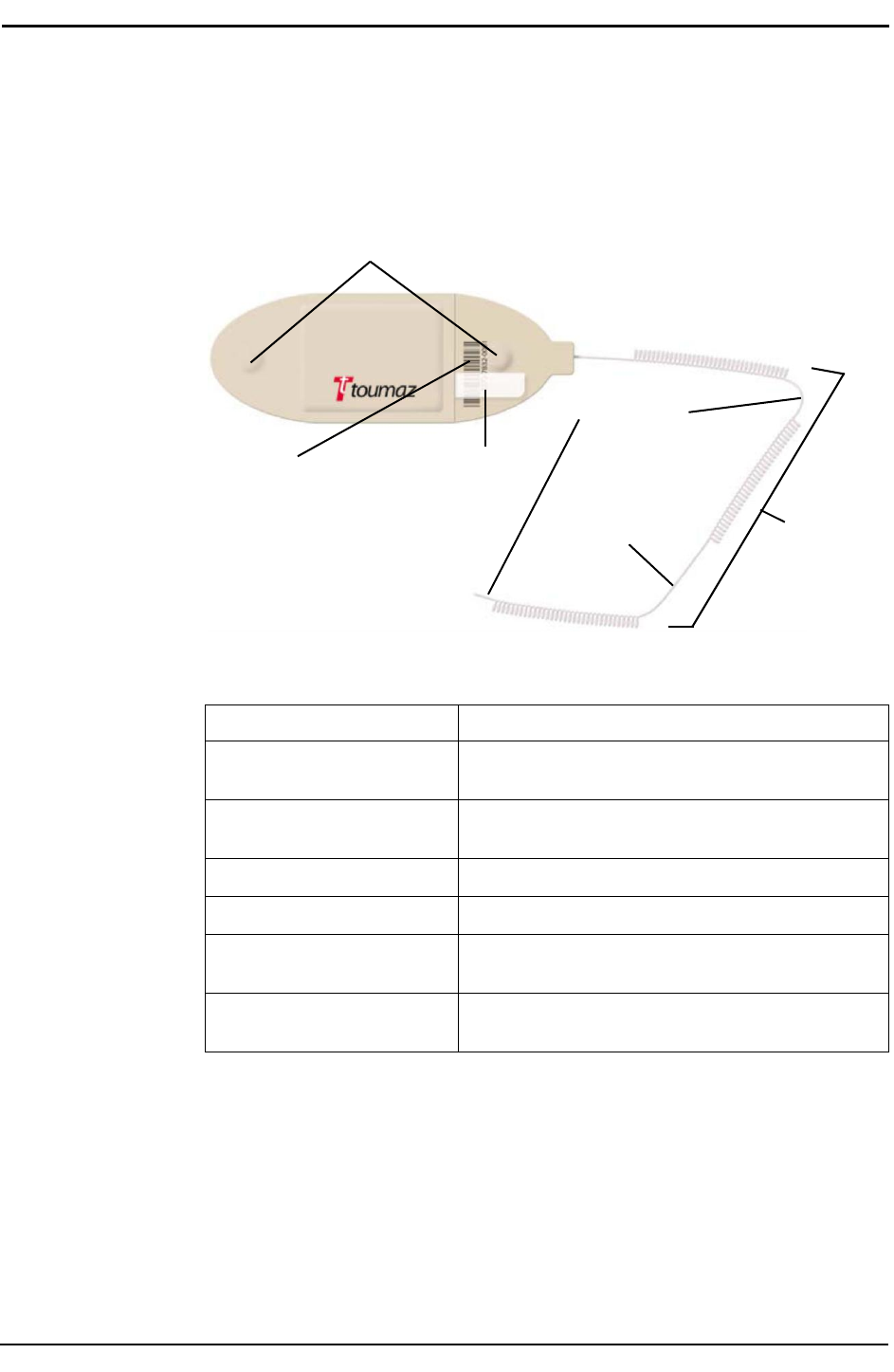
Patch components
The disposable patch, when applied to the patient and activated, collects and
transmits patient vital sign data: heart rate, respiratory rate, and axillary
temperature. The vital sign data are then displayed on the Wireless
Monitoring Application.
Electrode connectors
Attachment points
Patch ID Activation tab
Axillary
section
Temperature
sensor
Patch component descriptions
Item
Description
Electrode
connectors
Connectors
on the
underside
of the
patch
where
monitoring electrodes
are attached.
Patch
ID
Barcode
and
number which uniquely identify
the
patch.
Activation
tab
Removing
this tab
activates
the patch.
Temperature
sensor
Used
to
read
the
patient’s axillary
temperature.
Attachment
points
Used
to
secure
the
temperature sensor
in the
proper location.
Axillary
section
The part of the
temperature sensor which
is
placed
beneath
the
patient’s
axilla.
6
TZ202000-IFU Wireless Monitoring System Directions for Use
Chapter 1—General Information
Wireless Monitoring Application screens
The Wireless Monitoring Application is a web-based application accessed using
Internet Explorer on a standard hospital PC computer.
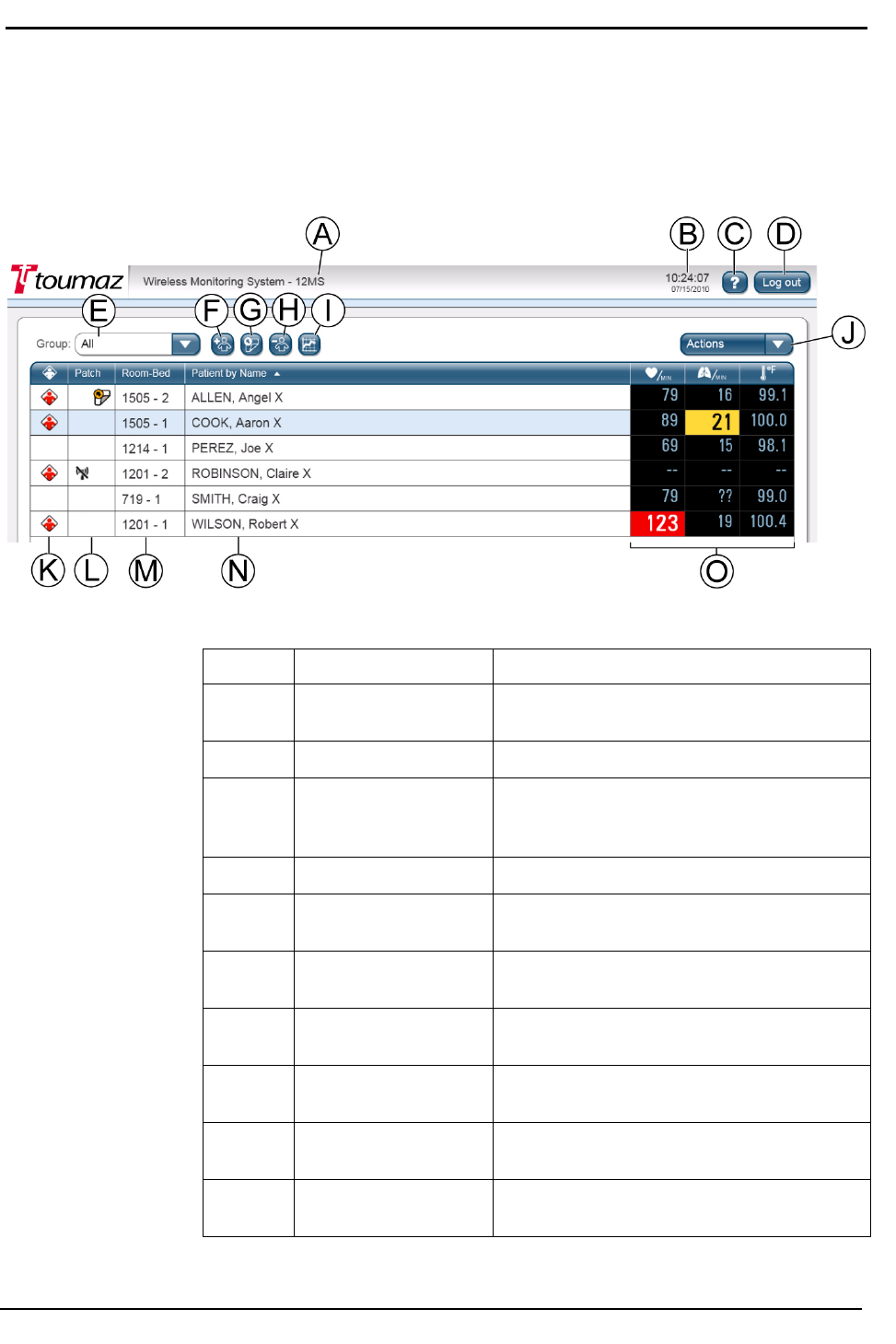
Main screen
Main screen components
Identifier
Component
Description
A
Unit
name
Displays
the unit for
which
the data is being
displayed.
B
System time
and date
Displays
the
current system time
and date.
C
About button
Displays SensiumVitals Wireless Monitoring
System
information
and
provides
a link to
online
help.
D
Log out button
Logs
you out of the system.
E
Group
drop-down
list
Allows
you to
display
a
particular group
in a
unit or
display
all
patients
in the unit.
F
Add Patient button
Allows
you to add a
patient
to
wireless monitoring.
G
Replace Patch button
Allows you
to
replace
a
patch on
a
patient
being monitored.
H
Remove Patient button
Allows
you to
remove
a
patient from
wireless
monitoring.
I
Patient History button
Allows
you to
view patient vital sign
history
and
access patient
settings.
J
Actions
drop-down
list
Allows
you to
assign beds (depending
on
access rights)
and run a
Clinical Data
Report.

TZ202000-IFU Wireless Monitoring System Directions for Use
7
System information
Main screen components (continued)
Identifier
Component
Description
K
Notification
column
Displays
a
notification icon
(see Monitoring
symbols
on
page
2) if
there
is a
notification
for
that
patient. Click
the
icon
to see notification
details. Click
the
column heading
to sort the
patients with open notifications
at the top of
the list.
L
Patch Status
column
Displays icons relating
to
patch status
(see
Monitoring symbols
on
page
2). If no
icon
is
displayed,
the
patch
is
okay. Click
the column
heading
to sort the
patients
by
patch
status.
Those patients whose patches require
attention
appear
at the top of the list.
M
Room-Bed
column
Indicates
the
patient’s room
and bed
number.
Click
the
column heading
to sort
patients
in
room-bed number
order.
N
Patient
by X column
Displays
a list of
patients currently
being
monitored.
By
default,
this list is
sorted
by
Name. Click the column heading to sort
patients by Vital Sign
Status, with
red and
yellow
vital sign
alerts
at the top of the list.
When
the list
displays
all
patients
in a
unit,
this
column displays only
the
patients’
names.
However, when
a
group
is
selected using
the
Group
drop-down
list, this
column displays
the
patient name,
ID, and
date
of birth.
O
Vital signs
columns
These columns display
the
latest vital
signs—
heart rate, respiratory rate,
and axillary
temperature—for each patient
in the list.
•
Vital signs that are within normal limits
are
displayed
in blue on a
black
background.
•
Vital signs
that
exceed yellow preset
limits
are
displayed
in
black
on a yellow
background.
•
Vital signs
that
exceed
red
preset limits
are
displayed
in
white
on a red background.
•
If the system receives invalid data,
question
marks
are displayed.
• If the
system
has not
received vital
sign
data
for a
period
of
time, dashes
are
displayed.
•
Dashes
are also
displayed while
a
patch
is
being
activated.
If the Patient list is long, vital sign warnings might appear below the
“bottom” of the Main Screen. To avoid this, use the Group drop-down
list to limit the number of patients shown.
8
TZ202000-IFU Wireless Monitoring System Directions for Use
Chapter 1—General Information
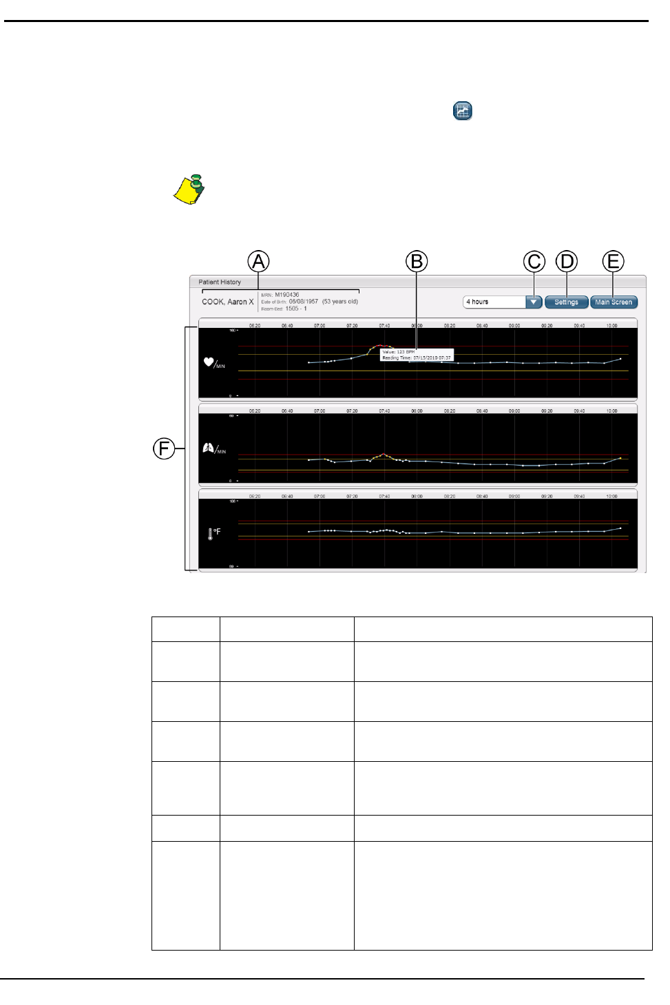
Patient History screen
To display the Patient History screen, do one of the following:
• Select a patient and click the Patient History button
• Click one of a patient’s vital signs on the main screen
Always verify in the Patient History screen that the correct patient’s
information is displayed (item A). If it is not, click Main Screen (item
E) and select the correct
patient.
Patient history screen components
Identifier
Component
Description
A
Patient demographic
data
Displays patient’s name,
ID, date of
birth,
age, and
room/bed
number.
B
Value
and
reading
time
of a vital sign data point
Move
the
mouse over
a
data point
on the
chart
to display.
C
Display Period drop-
down
list
Allows you
to
choose the period
of
time
to
display
vital
sign
data;
for
example,
for the last
four
hours.
D
Settings button
Displays
and
allows
you to
modify (depending
on
privileges)
vital sign
limits
and the
documentation interval.
E
Main Screen button
Returns
you to the
main
screen.
F
Vital sign
history
Displays
the
heart
rate,
respiratory
rate, and axillary
temperature
data
over
the
selected
time period.
Depending
on the
display period,
data
points
are
displayed
as
dots
or as line
segments. Data
points
within
the set
limits
are
displayed
in
blue.
Data points
outside
the
yellow limits
are
displayed
in
yellow.
Data
points outside
the red
limits
are
displayed
in red.
TZ202000-IFU Wireless Monitoring System Directions for Use
9
Chapter
2
Using the SensiumVitals Wireless
Monitoring System
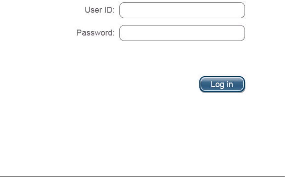
Logging in and out
The Wireless Monitoring Application is a web-based application accessed using
Internet Explorer on a standard hospital PC computer. Only authorized
personnel can log in to the Wireless Monitoring Application.
To log in
1. Enter your user ID and appropriate password at the Log in screen.
2. Click Log in.
The main screen appears.
10
TZ202000-IFU Wireless Monitoring System Directions for Use
Chapter 2—Using the Wireless Monitoring System
To log out
• Click Log out in the upper right corner of the main screen.
After a period of inactivity, the application automatically logs out.
Starting patient monitoring
Required equipment
CAUTION—Use of 3M Red Dot 2560 Monitoring Electrodes is
recommended.
• Patch
• 3M™ Red Dot™ 2560 Monitoring Electrodes (2)
• Skin cleaning solution
° Isopropyl alcohol or a special skin preparation solution can be used.
• Clipper
• Water-resistant plastic or paper medical tape such as 3M Transpore™ or 3M
Transpore™ White
Applying the patch
WARNING—Do not use the SensiumVitals Wireless Monitoring
system on critical care patients.
WARNING—Do not apply the patch on breached or compromised
skin surfaces or on mucosal membranes.
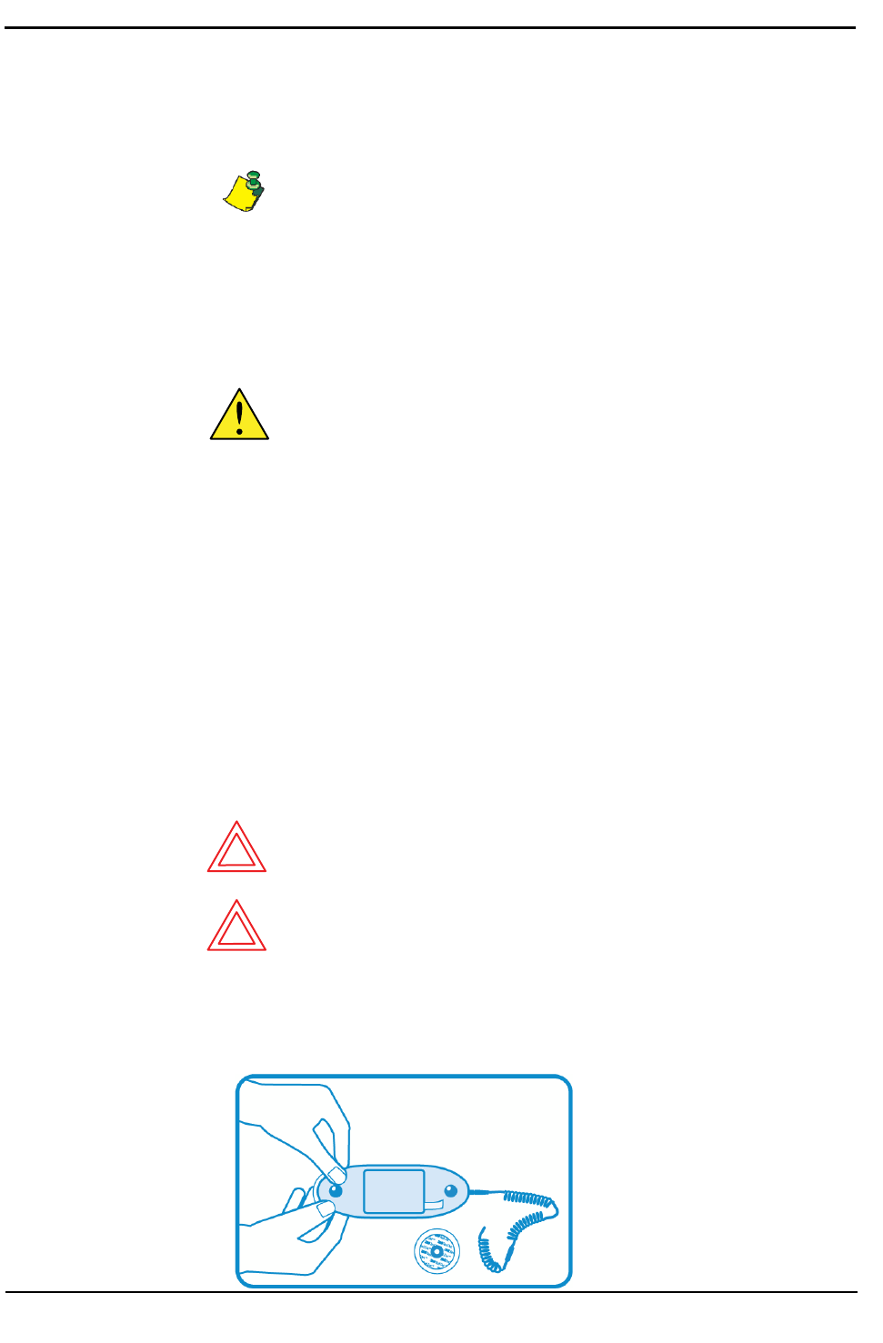
1. Open the patch packaging and inspect the patch to ensure that it is intact and
that the expiration date printed on the packaging has not been reached.
2. Connect each electrode to the patch as shown.
TZ202000-IFU Wireless Monitoring System Directions for Use
11
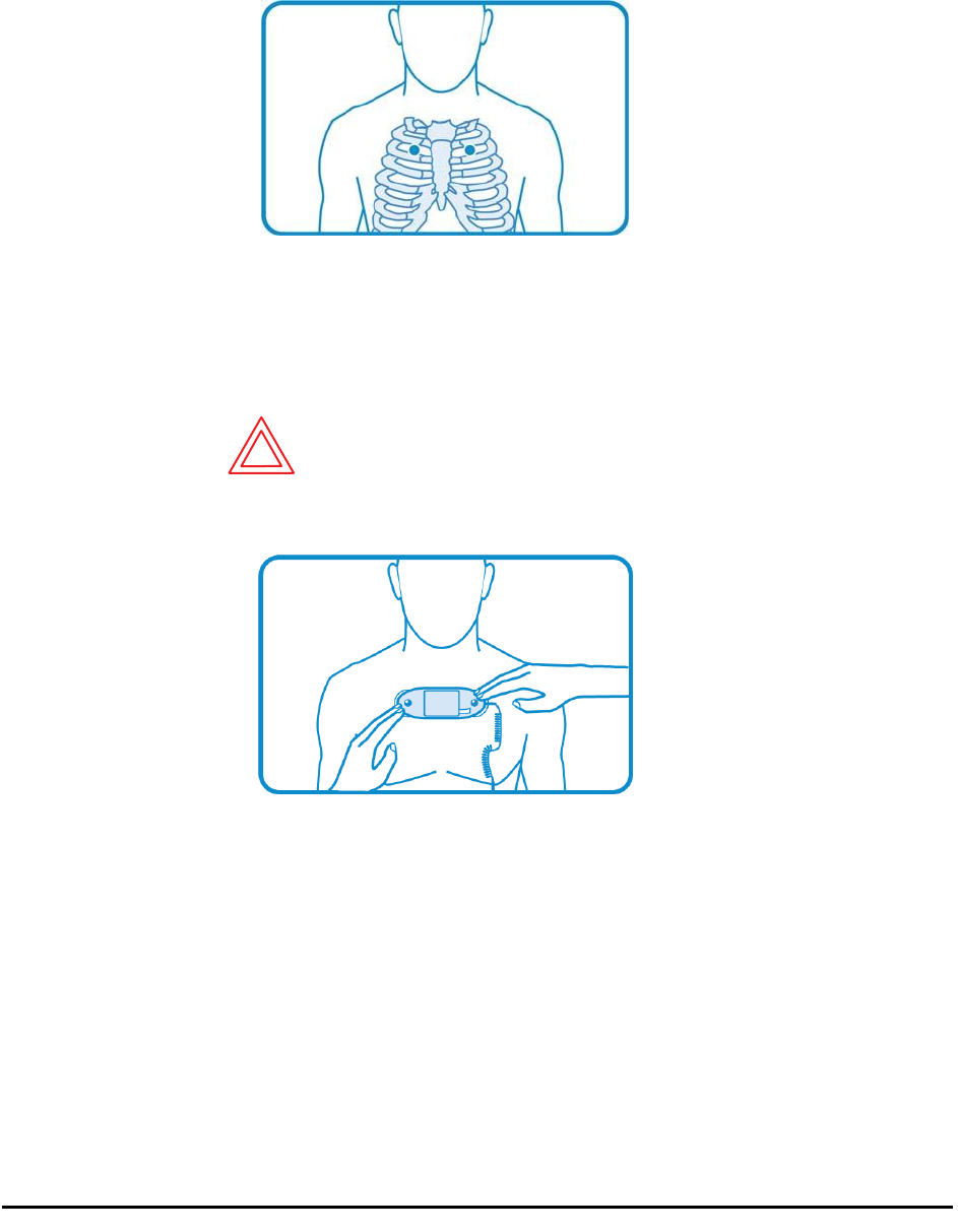
3. Without attaching the patch, but using the patch as a guide, locate the two
areas on the patient’s upper torso where the electrodes will be applied.
• Center the patch horizontally on the upper torso, with the center of the
electrodes on the second intercostal space.
4. Clip hair from the electrode sites and thoroughly clean the skin with an
approved skin cleansing solution; allow to dry.
• To avoid allergic reactions to the electrodes, refer to the electrode
manufacturer’s directions.
WARNING—Be sure to place the patch exactly as shown in these
instructions. An improperly-placed patch can return false data.
5. Apply the patch to the patient as follows:
a. Orient the patch so that the temperature sensor points toward the
patient’s non-dominant arm.
b. Peel off the backing from the electrodes and inspect the electrode gel to
make sure that it is intact and not dried out.
c. Apply the patch, making sure it is well centered on the torso with the
center of the electrodes on the second intercostal space, and pressing
lightly.
12
TZ202000-IFU Wireless Monitoring System Directions for Use
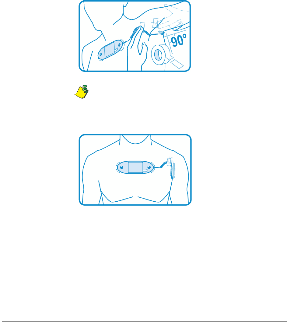
6. Apply the temperature sensor as follows:
a. Raise the patient’s arm to 90 degrees and center the axillary section
underneath the axilla.
b. Gently lift the two attachment points of the temperature sensor and
position them on either side of patient’s shoulder as shown in the
following figure.
c. Secure the temperature sensor to each attachment point location using
medical tape.
To avoid patient discomfort or skin irritation, do not create unnecessary tension
in the coils.
When installed correctly, the coils are only slightly extended and the two
attachment points are at approximately the same level as shown.
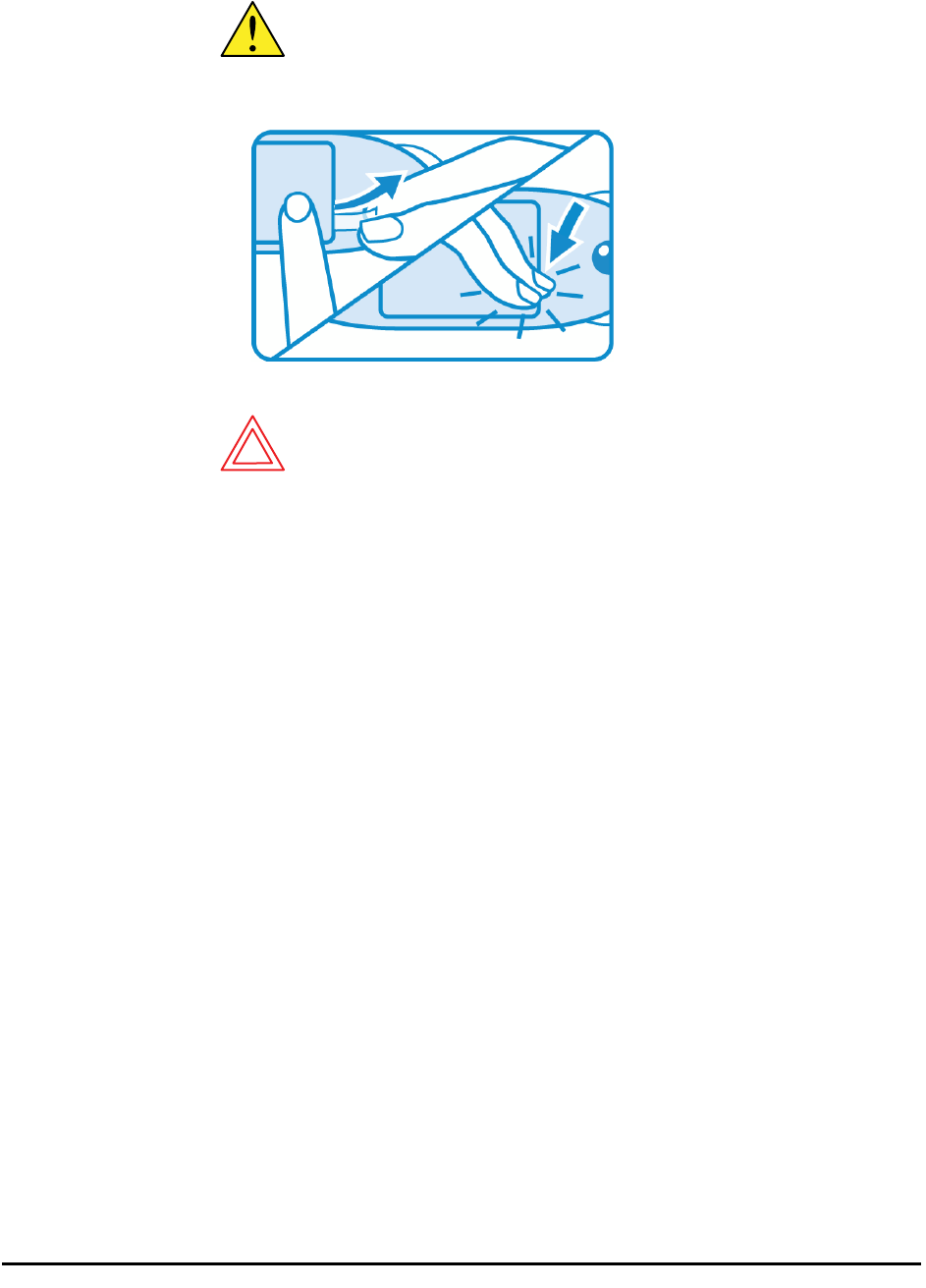
7. Pull out the activation tab.
TZ202000-IFU Wireless Monitoring System Directions for Use
13
CAUTION—Make sure the activation tab opening is perfectly
sealed after the patch has been activated.
Doing this helps avoid patch malfunctions due to moisture.
8. Press down on the activation tab opening to seal it shut.
WARNING—Patient interference with the patch can cause false
data to be sent.
9. Advise patient to not remove, pull on, adjust, or otherwise interfere with the
patch.
14
TZ202000-IFU Wireless Monitoring System Directions for Use
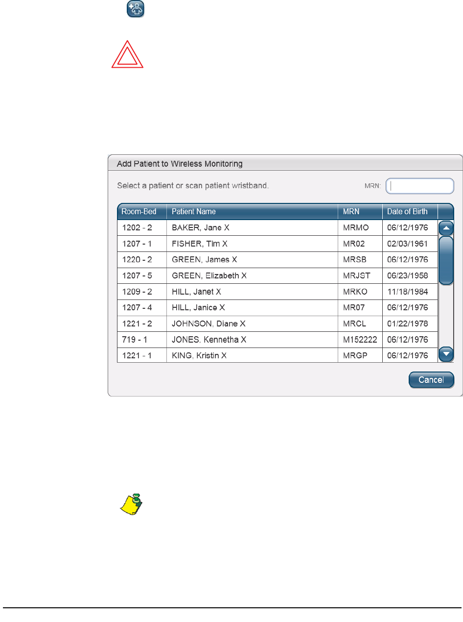
Adding patient to wireless monitoring
1. On the main screen of the Wireless Monitoring Application, click Add Patient
to open the patient list.
WARNING—Always verify that the patient’s information is
correct.
2. Do one of the following to open the Add Patient to Wireless Monitoring
screen:
• Scan the patient’s wristband.
• Select the appropriate patient from the list, as shown.
You can do either of the following to help you find the patient in the
patient list:
• Enter the MRN (or patient ID) in the text box to locate the patient.
• Click any column heading to sort by that column.
If the correct patient’s information is not displayed in the Add Patient to
Wireless Monitoring screen, click Cancel and select the correct patient.
If the correct patient is not listed, it is possible that the patient was
transferred to another unit, or was recently transferred into your unit
and the Hospital Information System has not yet been updated. Verify
the status of the patient in the HIS.
TZ202000-IFU Wireless Monitoring System Directions for Use
15
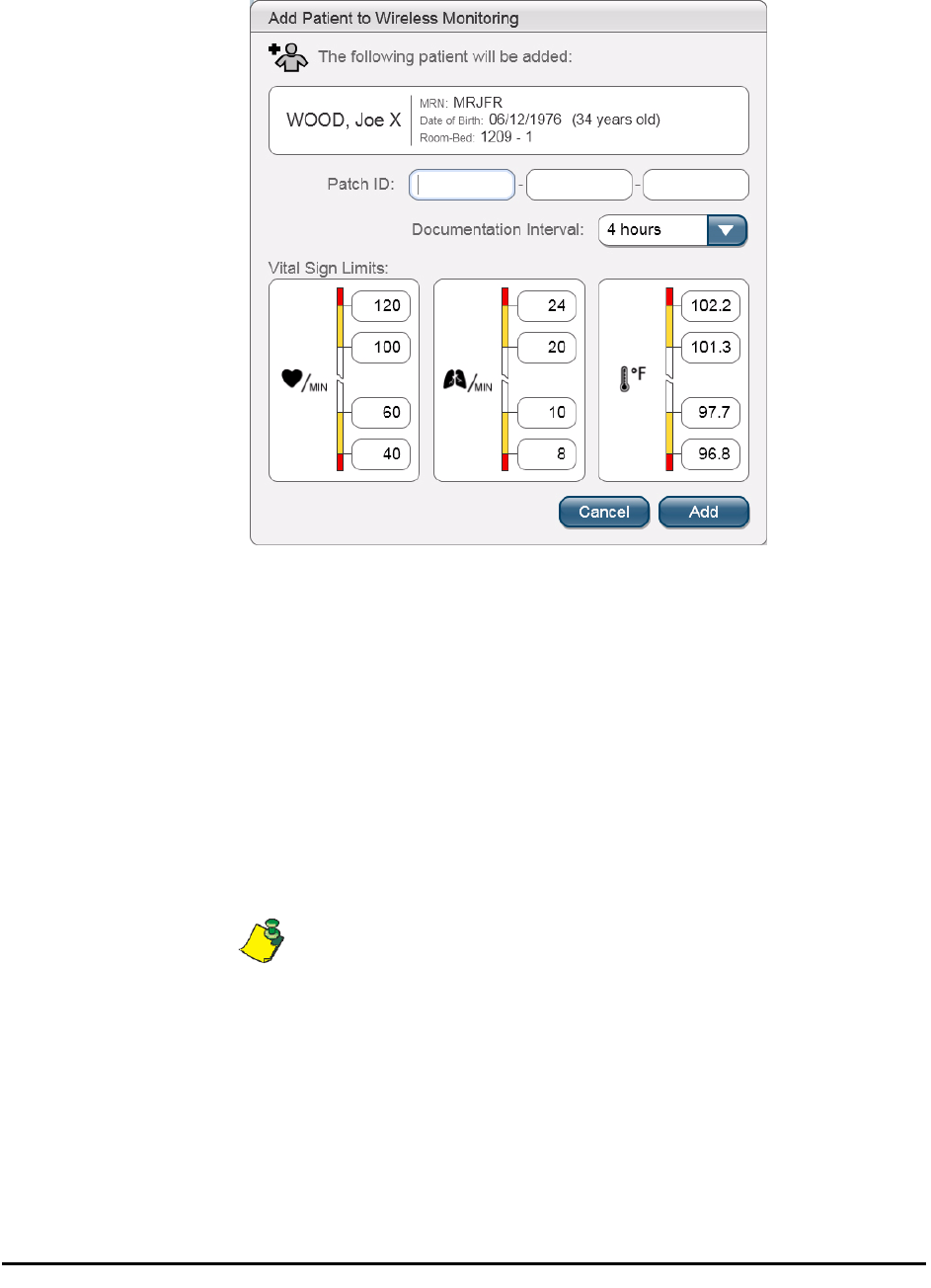
3. On the Add Patient to Wireless Monitoring screen, do the following:
a. Enter the new patch ID number using one of the following methods:
• Enter the ID number in the Patch ID text box.
• Scan the barcode on the patch.
The barcode appears on both the patch and the packaging. If you are
unable to scan the patch at the patient’s bedside, you can use the
patch ID on the packaging instead.
b. Set a documentation interval for transferring the data into the patient’s
electronic medical record:
i. Click the Documentation Interval drop-down list.
ii. Select the new time interval.
The Documentation Interval controls how often the system copies data
into the patient’s electronic medical record.
16
TZ202000-IFU Wireless Monitoring System Directions for Use
Standard yellow and red vital sign limits (yellow and red limits) are
defined and set by the hospital for all patients who are being monitored
with the SensiumVitals Wireless Monitoring System. Vital sign limits can
be modified
for a specific patient.
WARNING—Make sure that yellow and red vital sign limits are
appropriate to the patient’s condition.
c. Set vital sign limits as follows:
i. Click the text box that displays the vital sign limit you wish to change.
ii. Enter different upper and/or lower limits as needed.
Additional user privileges may be required to change some or all vital
sign limits.
d. After completing the required changes, click Add.
A message appears to confirm that the patient was added to monitoring.
4. Click OK to return to the main screen.
When a patient is added to monitoring, allow up to 15 minutes before
the data is available on the main screen.
Monitoring is intermittent. Vital sign data is usually updated once every
2 minutes, but can vary depending on the configuration of your unit.
.
TZ202000-IFU Wireless Monitoring System Directions for Use
17
Monitoring patients
Monitoring patients
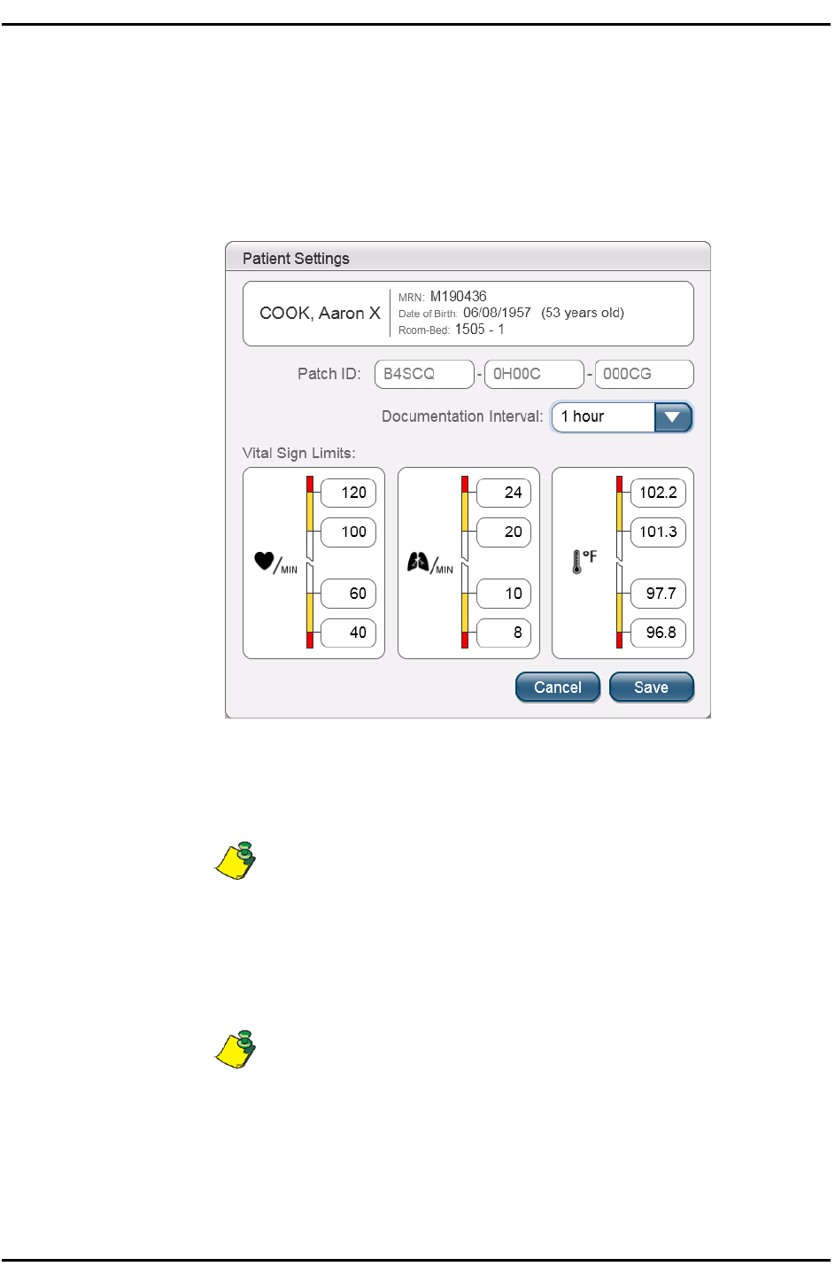
Editing patient settings and vital sign limits
1. On the Patient History screen, click Settings.
The Patient Settings screen appears.
2. To set a different documentation interval, do the following:
a. Click the Documentation Interval drop-down
list. b. Select a different documentation interval.
The Documentation Interval controls how often the system copies data
into the patient’s electronic medical record.
3. To change a vital sign limit, do the following:
a. Click the text box that displays the vital sign limit you wish to change.
b. Enter different upper and/or lower limits as needed.
Additional user privileges may be required to change some or all vital
sign limits.
4. When you have made the required changes, click Save.
A message confirms that the changes have been saved.
5. Click OK to return to the Patient History screen.
18
TZ202000-IFU Wireless Monitoring System Directions for Use
Chapter 2—Using the Wireless Monitoring System
Notifications
WARNING—Always address received notifications, even if they
are not for a patient under your care.
Physiological and system notifications are sent from the Monitoring Server to
the Wireless Monitoring Application and, if set up to do so, a handheld
notification device.
Receiving notifications
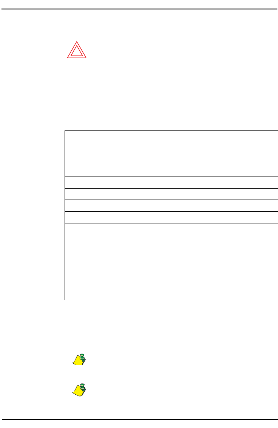
Notification types and descriptions
Type
Description
Physiological
Axillary
Temperature
Outside
of
yellow
or red
preset
limits
Heart
Rate
Outside
of
yellow
or red
preset
limits
Respiratory
Rate
Outside
of
yellow
or red
preset
limits
System
Replace
Patch
Two hours
of use remaining
Replace Patch
Now
Patch
is no
longer
functional
Signal
Lost
Patch
is
outside
of
coverage
area
beyond
a specified
length
of
time. Caregiver
is
advised
to
check
on the
patient
if it is
unknown why the patient
is no
longer
being monitored.
This notification may
also
appear
if the
patch
was
improperly
activated.
Reading
Problem
The
system
was
unable
to
interpret vital sign
data
for
several attempts
in a row.
This notification may
also
appear
if the
patch
was
incorrectly
attached.
Acknowledging Notifications
When a notification is received, it must be acknowledged in the Wireless
Monitoring Application.
Depending on your system configuration, vital sign notifications may
not be sent until two or more consecutive yellow or red vital sign
statuses are recorded.
Depending on your system configuration, some notifications may not
require acknowledgement.
TZ202000-IFU Wireless Monitoring System Directions for Use
19
Monitoring patients
To acknowledge a notification from the Wireless Monitoring
Application
1. At the main screen, click the notification symbol associated with the
appropriate patient.
The Acknowledge Notifications window displays both the physiological
and system notifications for that patient.
2. Click Acknowledge.
A message confirms that notifications have been acknowledged.
3. Click OK to return to the main screen.
Reminder notifications
When a notification is not acknowledged within a specified period of time, a
reminder notification may be sent. Reminder notifications contain the same
information as the original notifications that they refer to.
20
TZ202000-IFU Wireless Monitoring System Directions for Use
Chapter 2—Using the Wireless Monitoring System
Escalation notifications
When a notification is not acknowledged within a specified period of time, an
escalation notification may be sent to another caregiver handheld device.
Escalation notifications contain the same information as the original
notifications that they refer to.
Replacing a Patch
1. Remove the patch, electrodes, and temperature sensor from the patient.
2. Dispose of the patch in accordance with the hospital waste procedure.
WARNING—The patch is a single-use device. After the patch is
removed from a patient, do not reuse the patch, whether on the
same patient or on a different patient.
3. Apply a new patch to the patient as described in Applying the patch
on page 10.
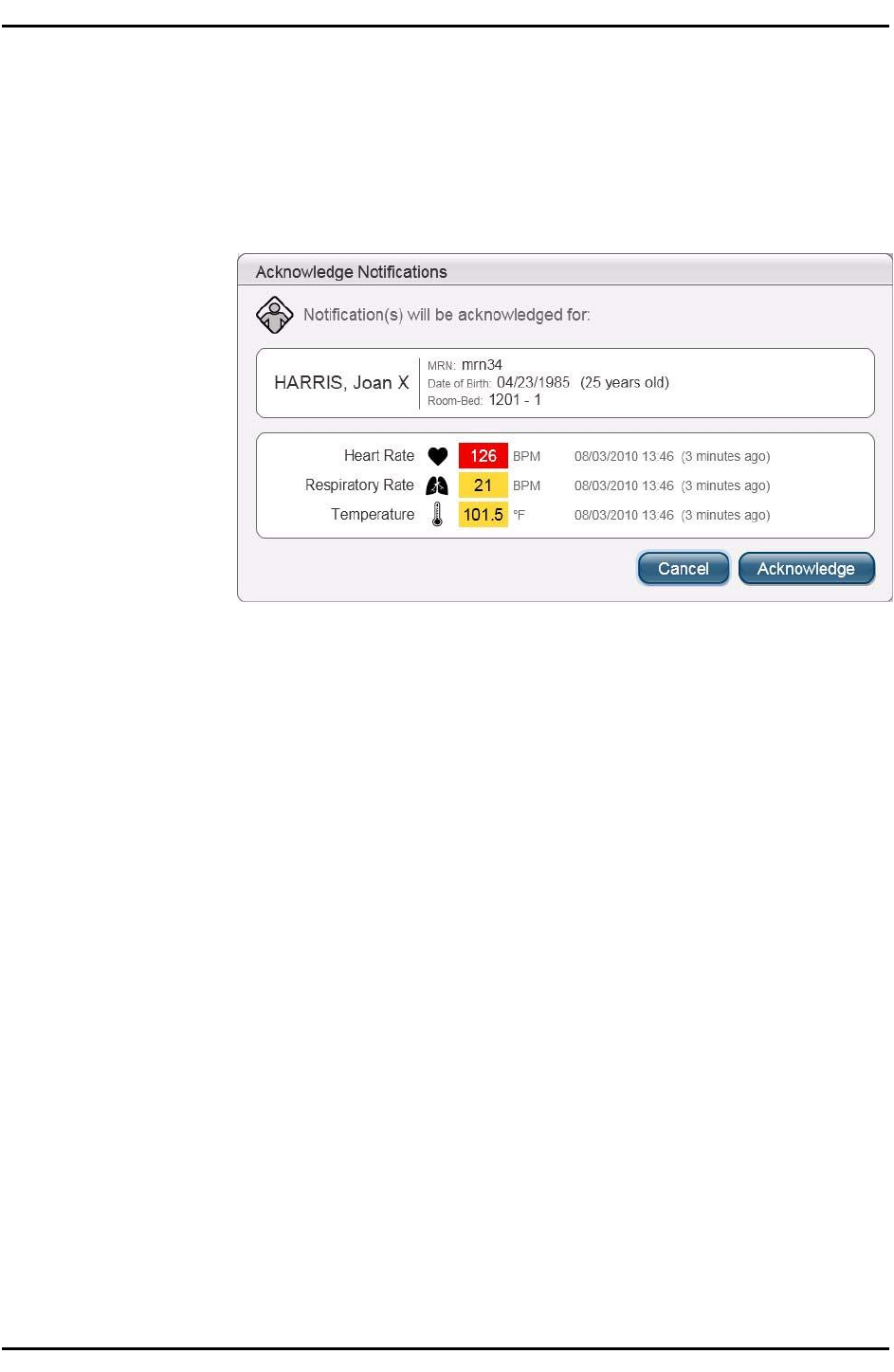
Updating patch information in the Wireless Monitoring
Application
1. On the main screen, select the patient whose patch was replaced and click
Replace Patch .
2. Do one of the following to enter the new patch ID number:
• Enter the new ID number in the New Patch ID text box.
• Scan the barcode on the patch.
The barcode appears on both the patch and the packaging. If you are
unable to scan the patch at the patient’s bedside, you can use the patch
ID on the packaging instead.
3. Click Replace.
A message confirms that the patch has been replaced.
4. Click OK to return to the main screen.
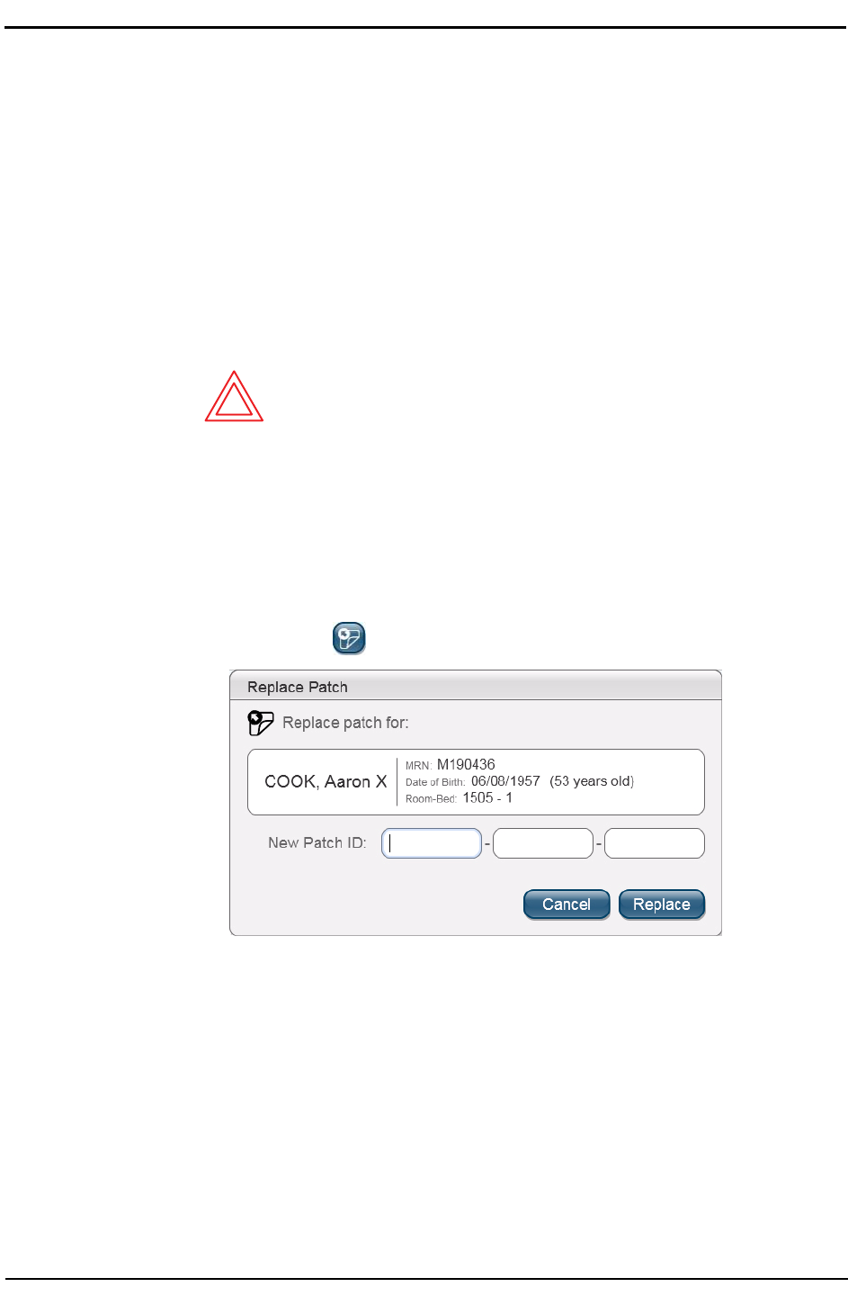
Removing a patient from wireless monitoring
TZ202000-IFU Wireless Monitoring System Directions for Use
21
Removing a patient from wireless
monitoring
1. Remove the patch, electrodes, and temperature sensor from the patient.
2. Dispose of the patch in accordance with the hospital waste procedure.
WARNING—The patch is a single-use device. After the patch is
removed from a patient, do not reuse the patch, whether on the
same patient or on a different patient.
3. On the main screen of the Wireless Monitoring Application, select the patient
to be removed from wireless monitoring and click Remove Patient .
The Remove Patient from Wireless Monitoring screen appears.
4. Click Remove.
A message confirms that the patient was removed from monitoring.
5. Click OK.
The main screen appears.
Chapter 2—Using the Wireless Monitoring System
22
TZ202000-IFU Wireless Monitoring System Directions for Use
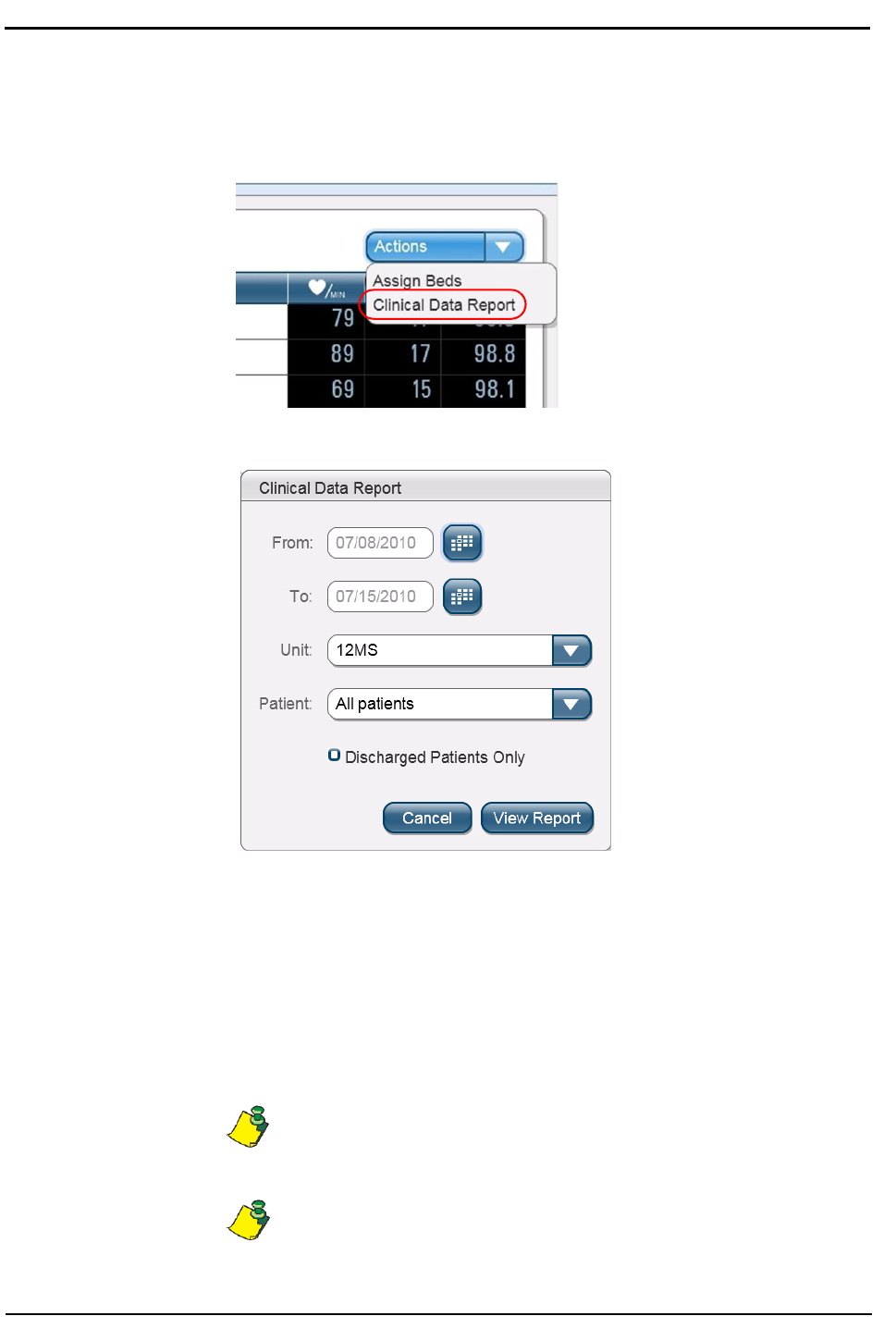
Running a Clinical Data Report
1. From the Actions drop-down list on the main screen, select Clinical Data
Report.
The Clinical Data Report dialog box appears.
2. In the From and To boxes, enter the date range for the report.
Alternatively, click the calendar icons to select the date range from calendars.
3. Select the unit for the report from the Unit drop-down list.
4. Select a patient, or select All patients, from the Patient drop-down list.
• Select Discharged Patients Only to include only discharged patients in
the report.
5. Click View Report.
The report can take several minutes to generate and be displayed.
You can print a clinical data report by clicking the print icon in the Adobe
Acrobat Reader menu bar.
TZ202000-IFU Wireless Monitoring System Directions for Use
23
Assigning beds to groups
Assigning beds to groups
Beds can be assigned to groups within a unit. A group can then be selected on
the main screen using the Groups drop-down list, and only patients in beds
assigned to that group will appear on the list. Notifications for patients in that
group are sent to the corresponding notification devices, as configured by IT for
the group.
Patients admitted in a unit but without room/bed information can still be
monitored and are considered part of the Default Bed Group. See Step 3,
below.
Additional user privileges are required to use the Assign Beds feature.
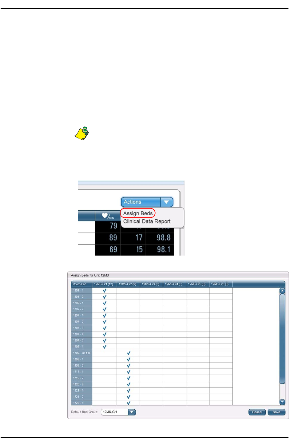
Assigning beds to groups
1. From the Actions drop-down list, select Assign Beds.
The Assign Beds screen appears.

24
TZ202000-IFU Wireless Monitoring System Directions for Use
Chapter 2—Using the Wireless Monitoring System
2. Click a cell in the group column to assign a bed to a group.
A blue check mark indicates the assigned group for a bed. A bed can be
reassigned as often as needed.
3. To set the group to which patients are admitted without room/bed
information assigned, click the Default Bed Group drop-down list and select
a group.
4. Click Save.
A message confirms that your selections have been saved.
5. Click OK to return to the main screen.

TZ202000-IFU Wireless Monitoring System Directions for Use
25
Chapter
3
Troubleshooting
Logging in and out
I am entering the correct user name and password, but the system is
not logging me in
• Your computer’s CAPS LOCK may be on. If so, turn it off and try again.
• If that doesn’t work, double-check your user name and password.
• If your user name and password are correct and the system still won’t log you
in, contact your facility’s IT department for assistance.
Adding a patient
Scanning the patient’s or patch’s bar code doesn’t work
Sometimes bar codes don’t print properly, and scanners have a hard time reading
them. If you attempt to scan a bar code and it doesn’t work, enter the code
manually.
If the problem persists with different bar codes, then you may have a faulty
scanner. Contact your facility’s IT department for assistance.
I need to add a patient to wireless monitoring, but the patient’s name
isn’t in the list
There are several reasons why a patient’s name may not be in the Add patient
to wireless monitoring list:
• The patient may have already been added to wireless monitoring. Check the
main screen, then follow the procedures under The patient’s name is not
displayed on the main screen on page 26 to see if the patient is already
being monitored.

26
TZ202000-IFU Wireless Monitoring System Directions for Use
Chapter 3—Troubleshooting
• The patient may have recently been admitted or transferred to your unit,
and the system hasn’t been updated yet.
If neither of the above applies, check with your facility’s IT department for
assistance.
I am unable to access the Assign Bed feature
Additional user privileges are required to assign beds. Ask someone who has these
privileges for assistance.
If you know that you should have access to this feature, but you do not, contact
your facility’s IT department for assistance.
I can’t change the vital sign limits
Additional user privileges may be required to change some or all vital sign limits.
Ask someone who has these privileges for assistance.
If you know that you should have the ability to change vital sign limits, but you do
not, contact your facility’s IT department for assistance.
The patient’s demographic information is incorrect
The SensiumVitals Wireless Monitoring System’s patient information is taken from
the Hospital Information System (HIS). Check with the HIS administrator to make
sure that all information is correct and up to date.
Monitoring a patient
The patient’s name is not displayed on the main screen
If the patient’s name is not visible on the main screen, check the following:
• Check the Group drop-down list to make sure that the proper group is being
shown, or select All to display all patients being monitored.
• If there is a scroll bar to the right of the patient list, the list is too long to be
displayed on one screen. Scroll down to see if the patient is farther down the
list.
• It is possible that the patient was not added to wireless monitoring, even if a
patch was applied and activated. Follow steps 1 and 2 of the procedure Adding
patient to wireless monitoring on page 14. If the patient’s name is on the
Patient List screen, follow the rest of the procedure to add the patient to
wireless monitoring.
• It is also possible that the patient was transferred to another unit, or was
recently transferred into your unit and the Hospital Information System has
not yet been updated. Verify the status of the patient in the HIS.
If, after doing all of the previous steps, the patient’s name still is not displayed on
the main screen, contact your facility’s IT department for assistance.

TZ202000-IFU Wireless Monitoring System Directions for Use
27
Monitoring a patient
(
The patient’s vital sign data are not appearing on the main screen
If a patient’s vital sign data aren’t being read by the system, the vital sign
data columns show dashes (--). If this is the case, check the following:
• Check the Patch column to see if the “Patch Activating” icon ( ) is
displayed. If so, wait a few minutes for it to disappear.
NOTE: The patch can take up to 15 minutes in the worst case to
activate and display data on the main screen.
• Check the Patch column to see if the Out of Range/Signal Lost icon ( ) is
displayed. If so, see The Patch status column displays the Out of Range/ Signal
Lost icon on page 28.
• Check the Patch column to see if the “Replace Patch” icon ) is displayed.
If so, replace the patch following the instructions under Replacing a Patch on
page 20.
• Make sure that the activation tab has been removed.
• If you have checked all of these items, properly applied and activated the
patch, and the patient is not out of range, the patch may be faulty. Wait a few
minutes for the next reading. If dashes (--) are still displayed, replace the patch
following the instructions under Replacing a Patch on page 20.
If, after doing all of the previous steps, the vital sign data columns still display
dashes (--), contact your facility’s IT department for assistance.
There are question marks (??) in the patient’s heart rate column
This is normal, but should not happen often. It can be due to temporary electrical
interference, the patient moving in certain ways, or something striking the patch.
However, if the question marks persist, check the following:
• Make sure that the patch is properly placed on the patient.
• Make sure that the electrodes are firmly attached to the patch and to the
patient.
• Replace the monitoring electrodes with fresh electrodes.
• If the problem persists for longer than a specified period of time, the system
will send a notification to replace the patch. If this is the case, replace the
patch following the instructions under Replacing a Patch on page 20.
If, after doing all of the previous steps, the heart rate column still displays
question marks (??), contact your facility’s IT department for assistance.
There are question marks (??) in the patient’s respiratory rate
column
Due to the nature of impedance pneumography, it is possible that respiratory rate
readings are often not available, especially when the patient is moving. It can take
several minutes after the patient has stopped moving for respiratory rate data to
be

28
TZ202000-IFU Wireless Monitoring System Directions for Use
Chapter 3—Troubleshooting
displayed. However, if the patient is not moving and question marks persist, do the
following:
• Make sure that the patch is properly placed on the patient.
• Make sure that the electrodes are firmly attached to the patch and to the
patient.
• Replace the monitoring electrodes with fresh electrodes.
• If the problem persists for longer than a specified period of time, the system
will send a notification to replace the patch. If this is the case, replace the
patch following the instructions under Replacing a Patch on page 20.
If, after doing all of the previous steps, the respiratory rate column still displays
question marks (??), contact your facility’s IT department for assistance.
There are question marks (??) in the patient’s temperature column
Temperature readings might become unavailable if the patient is moving or if the
patient’s arm is not covering the temperature sensor completely. It can take several
minutes after the patient’s arm has returned to the proper position for
temperature data to be displayed. Question marks can also be displayed if the
patient experiences a rapid drop in core body temperature.
If question marks persist, check the following:
• Make sure that the temperature sensor is properly placed on the patient.
• If the problem persists for longer than a specified period of time, the system
will send a notification to replace the patch. If this is the case, replace the
patch following the instructions under Replacing a Patch on page 20.
If, after doing all of the previous steps, the temperature column still displays
question marks (??), contact your facility’s IT department for assistance.
The Patch status column displays the Out of Range/Signal Lost icon
If the Out of Range/Signal Lost icon ( ) is displayed in the Patch column, check
the following:
• The signal loss may be temporary. Wait a few minutes for the next patch
reading. If the icon goes away, the signal has been restored.
• If the Out of Range/Signal Loss icon remains, verify the location of the patient.
The patient may have been temporarily moved to an area where there is no
coverage.
• If the Out of Range/Signal Loss icon is still displayed, and the patient is in the
assigned room, the patch may be faulty. Replace the patch following the
instructions under Replacing a Patch on page 20.
If, after doing the previous steps, the Patch column still displays the Out of Range/
Signal Lost icon, contact your facility’s IT department for assistance.
A patient appears in my group list, but isn’t under my care
Check to make sure that bed assignments are up to date. A bed that another
caregiver is responsible for may have been inadvertently assigned to you.

TZ202000-IFU Wireless Monitoring System Directions for Use
29
Patient History
Also, your group could be the “default group” to which patients without
room/bed information are assigned. The patient will be removed from your
group when the room/bed information has been updated.
It may also be that the patient was recently transferred into your group in the
system, but has not yet been physically moved.
Patient History
Some data points in the Patient History screen are 10 minutes apart
and others are 2 minutes apart
This is normal and not a cause for worry. Vital sign data is usually updated once
every 10 minutes, but can vary depending on the configuration of your unit.
Frequency automatically increases to as much as once every two minutes when
the vital sign data are outside of preset limits.
Some data points in the Patient History screen are yellow or red
when they’re within the vital sign limits
This is normal and not a cause for worry. A data point is marked yellow or red if it
falls outside of the yellow or red vital sign limits at the time it was recorded. If the
vital sign limits are later changed, yellow and red dots may fall within the new
limits.
Some data points in the Patient History screen are blue when they’re
outside the vital sign limits
This is normal and not a cause for worry. A data point is marked blue if it falls
within the yellow vital sign limits at the time it was recorded. If the vital sign limits
are later changed, blue dots may fall outside the new limits.
Removing patients from Wireless
Monitoring
A patient has been discharged, but the patient’s name is still on the
wireless monitoring list
Even if a patient is discharged from a facility, the patient must be manually
removed from wireless monitioring using the procedures under Removing a
patient from wireless monitoring on page 21.
General application questions
Online help doesn’t work
Contact your facility’s IT department.

30
TZ202000-IFU Wireless Monitoring System Directions for Use
Chapter 3—Troubleshooting
Clinical reporting doesn’t work
Contact your facility’s IT department.
Notification questions
There is a notification on the main screen, but the notification was
never sent to my pager
Check to make sure that bed assignments are up to date. The bed you believe you
are responsible for may have been inadvertently assigned to another caregiver.
If you are not receiving pages for any patients, contact your facility’s IT
department to have your pager serviced or replaced.
I am receiving notifications for patients not under my care
WARNING—Always address received notifications, even if they
are not for a patient under your care.
Check to make sure that bed assignments are up to date. A bed that another
caregiver is responsible for may now be assigned to you.
Also, your group could be the “default group” to which patients without room/bed
information are assigned. You will stop receiving notifications when the patient’s
room/bed information has been properly entered.
A patient’s vital sign data is yellow or red, but I didn’t receive a
notification
This is normal and not a cause for worry. Depending on your system configuration,
vital sign notifications may not be sent until two or more consecutive yellow or red
vital sign statuses are recorded.
It is also possible, depending on your system configuration, that notifications are
turned off for your system. Check with your facility’s IT department to verify this.
If you are not receiving pages for any patients, contact your facility’s IT
department to have your pager serviced or replaced.
Error message questions
The message “Internet Explorer cannot display the webpage”
displays when I tried to open the main screen
Try again. If the problem persists, contact your facility’s IT department for
assistance.

TZ202000-IFU Wireless Monitoring System Directions for Use
31
Appendix A
Technical Specifications
Performance specifications
Item
Specification
Heart
rate
30–200 beats
per
minute (bpm)
± 2 bpm
Respiratory
rate
5–60 breaths
per
minute (BPM)
± 2 BPM
Temperature
sensor
For
axillary temperatures from 89.6
°–
111.2
°
F
(32°–44°C)
within 0.4°F (± 0.2°C)
Patch specifications
Item
Specification
Patch
Weight
15 g
Duration
of Use
Up to 5 days
Operating
Temperature
50°–113°F
(10°–45°C)
Storage
Temperature
-4°–140°F
(-20°–60°C)

32
TZ202000-IFU Wireless Monitoring System Directions for Use
Appendix A—Technical Specifications
TZ202000-IFU Wireless Monitoring System Directions for Use
33
Appendix B
Compliance and Safety Info
FCC compliance statement (United States)
Patch FCC ID: AEJ-TZ202055R1. Bridge FCC ID: AEJ-TZ202020R1.
These devices comply with Part 15 of the Federal Communications Commission
(FCC) Rules. Operation is subject to the following two conditions:
1. These devices may not cause harmful interference.
2. These devices must accept any interference received, including interference
that may cause undesired operation.
CAUTION: Changes or modifications to these units not expressly
approved by the party responsible for compliance could void the
user’s authority to operate these units.
These units have been tested and found to comply with the limits for a Class A
digital devices, pursuant to Part 15 of the FCC Rules. These limits are designed to
provide reasonable protection against harmful interference in a non-residential
installation. These units generate, use and can radiate radio frequency energy and,
if not installed and used in accordance with the manufacturer’s instructions, may
cause interference harmful to radio communications.
Please insure all warning and caution icons noted in this DFU are
reviewed, understood and followed.

Appendix B—Compliance and Safety Info
34
TZ202000-IFU Wireless Monitoring System Directions for Use
Safety
Patch—Safety
Regulations
Compliance Tests
IEC
60529
Degrees
of
protection provided
by
enclosure
(IP
Code)
IP64 Dust-tight
and
Splashing
Proof
IEC
60601-1
Medical electrical
equipment
General Requirements
for Safety
Patient leakage current
< 10
µA
Dielectric Strength
@
500 V
IEC
60601-2-27
Medical electrical
equipment
Particular requirements
for the
safety,
including
essential performance,
of
electrocardiographic
monitoring
equipment
Heart
rate: 30 to 200 +/- 2 bpm
IEC
60601-2-49
Medical electrical
equipment
Particular requirements
for the
safety
of
multifunction
patient monitoring
equipment
BF
type applied
part
ISO
10993
Biological Evaluation
of
Medical Devices
Package
Cytotoxicity
Irritation
and delayed-
type hypersensitivity
ASTM F2475
- 05
Standard Guide
for
Biocompatibility Evaluation
of
Medical Device Packaging
Materials
Cytotoxicity
Physicochemical
ISO
80601-2-56
Particular requirements
for
basic safety
and
essential
performance
of
clinical thermometers
for body
temperature
measurement
Body temperature: 32°C to 44°C
+/-
0.2°
Bridge—Safety
Regulations
Compliance Tests
IEC
60950-1
Information technology
equipment
Safety general
requirements
Safety
for
interface with
Telecommunication
Network
Equipment
FCC Radiation Exposure Statement
This equipment complies with FCC radiation exposure limits set forth for an
uncontrolled environment. The bridge should be installed and operated with
minimum distance 20 cm between the radiator and your body.
This transmitter must not be co-located or operating in conjunction with any other
antenna or transmitter. IEEE 802.11b or 802.11g operation of this product in the
USA is firmware-limited to channels 1 through 11.

TZ202000-IFU Wireless Monitoring System Directions for Use
35
Electromagnetic
compatibility
Electromagnetic compatibility
Patch—Electromagnetic Compatibility
Regulations
Compliance Tests
IEC
60601-1-2
Medical electrical
equipment
Collateral
standard:
Electromagnetic
Compatibility
-
Requirements
and tests
Emissions:
30 to 230
MHz
40 dBµV/m
230 to
1000 MHz
47 dBµV/m
ESD:
+/- 8 kV Air discharges
+/- 6 kV
Contact
discharges
RF field:
3
V/m,
80
MHz
to 2.5 GHz
Magnetic field:
3 A/m
IEC
62311
Assessment
of
electronic
and
electrical equipment
related
to
human exposure
restrictions
for
electromagnetic
fields
Frequency:
0 to 300 GHz
Magnetic
flux density:
100,000
to 0.1 µT
FCC, CFR
47,
Part
15
Intentional
radiation:
<
50mV/m
@ 3
Unintentional radiation @ 10m:
Frequencies (MHz)
dBµV/m
30–88
90
88–216
150
216–960
210
960+
300
FCC, CFR
47,
Part
18
Operating frequency:
915
MHz +/-13.0
MHz
EN 300 220-01
Electromagnetic
compatibility and
Radio
spectrum
Matters (ERM)
Short Range Devices
(SRD)
Output power class:
7a, 5 mW
Bridge—Electromagnetic
Compatibility
Regulations
Compliance Tests
IEC
60601-1-2
Medical electrical
equipment
Collateral
standard:
Electromagnetic
Compatibility
-
Requirements
and tests
Emissions:
30 to 230
MHz
40 dBµV/m
230 to
1000 MHz
47 dBµV/m
ESD:
+/- 8 kV Air discharges
+/- 6 kV
Contact
discharges
RF field:
3
V/m,
80
MHz
to 2.5 GHz
Magnetic field:
3 A/m

Appendix B—Compliance and Safety Info
36
TZ202000-IFU Wireless Monitoring System Directions for Use
Bridge—Electromagnetic
Compatibility
Regulations
Compliance Tests
FCC, CFR
47,
Part
15
Intentional
radiation:
<
50mV/m
@ 3
Unintentional radiation @ 10m:
Frequencies (MHz)
dBµV/m
30–88
90
88–216
150
216–960
210
960+
300
EN 300 220-01
Electromagnetic
compatibility and
Radio
spectrum
Matters (ERM)
Short Range Devices
(SRD)
Output power class:
7a, 5 mW