Senstar 24000 Bi-static Microwave Intrusion Detection System User Manual Installation operation guide
Senstar Corporation Bi-static Microwave Intrusion Detection System Installation operation guide
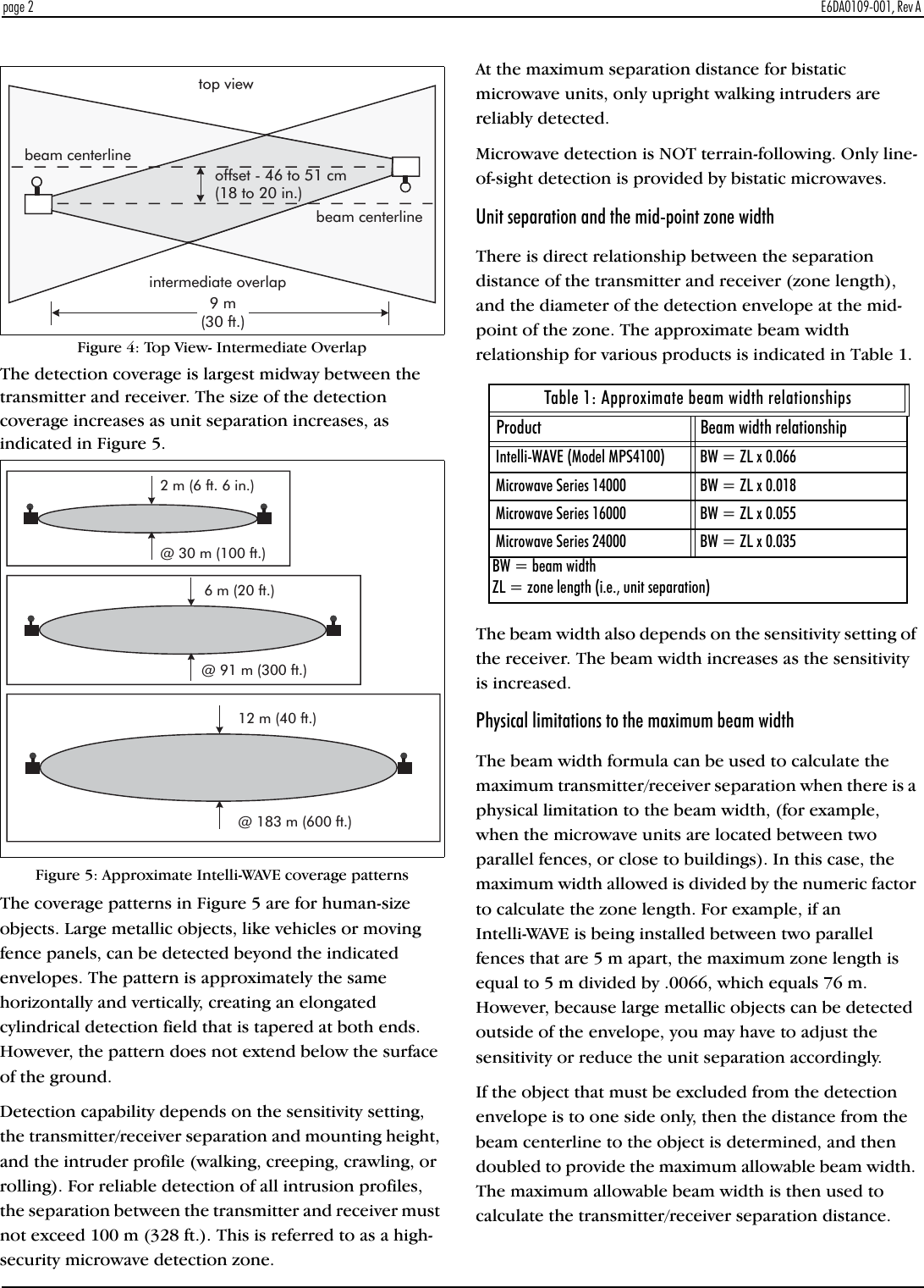
Senstar >
Contents
- 1. Installation and Operating Guide
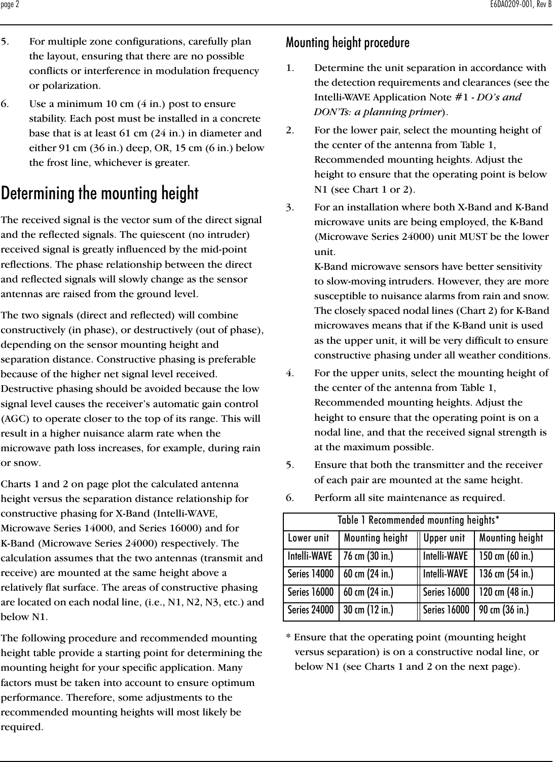
- 2. I5T14100 Installation and Operating Guide
- 3. I5T16000 Installation and Operating Guide
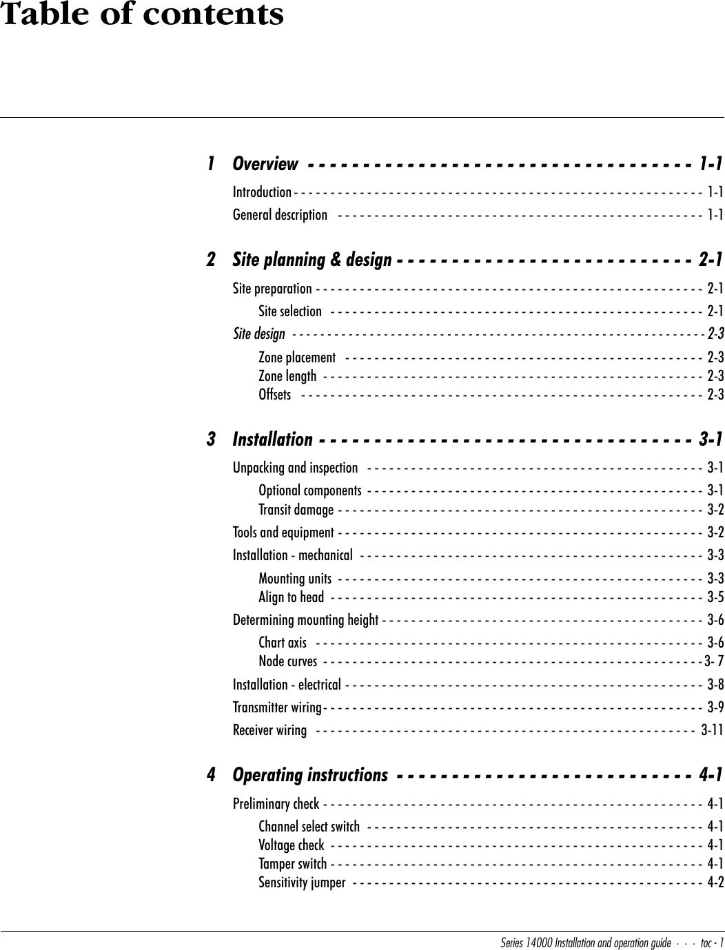
I5T14100 Installation and Operating Guide


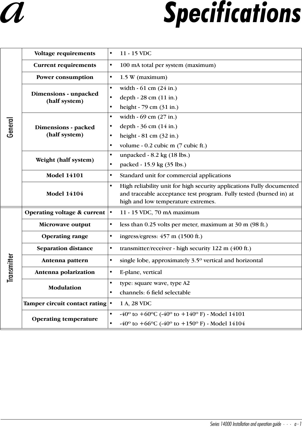
![D__\cQ^TUaeY`]U^d#"CUbYUc!$ 9^cdQ\\QdY_^Q^T_`UbQdY_^WeYTU10-Line RFI filterProvides filtering for radio frequency interference.Power distribution boxProvides convenient wiring interface between units and alarm reporting panel. Tamper switch and 115 V outlet receptacles are available.Power supply with standby batteryPlugs in to 115 VAC outlet, provides 2 A continuous power with 5 AH standby battery.Transit damageAlthough the transmitter and receiver are carefully packed, check for possible transit damage. If any damage has occurred in shipping, leave the packing carton and components intact and notify your carrier. Senstar-Stellar is not responsible for shipping damage.Tools and equipmentNomenclatureManufacturer/modelPurposedigital multimeterFluke 8062BMeasure Automatic Gain Control voltage during initial alignmentwrench, ratchet 13 mm x 14 mm box (1/2 in. x 9/16 in. box)Proto 1193Mount unit to post and adjust pitch of unitsScrewdriver, slot 15 cm long x 6 mm wide (6 in. long x 1/4 in. wide)commonConnect external leads to unit terminal boardScrewdriver, slot 10 cm long x 3 mm wide(4 in. long x 1/8 in. wide)commonAdjust sensitivity and alarm durationSphere, polished aluminum 30.5 cm (1 ft.) with sledUniversal Metal Spinning Albuquerque, NM 87110Adjust sensitivity in high-security applications](https://usermanual.wiki/Senstar/24000.I5T14100-Installation-and-Operating-Guide/User-Guide-688602-Page-12.png)
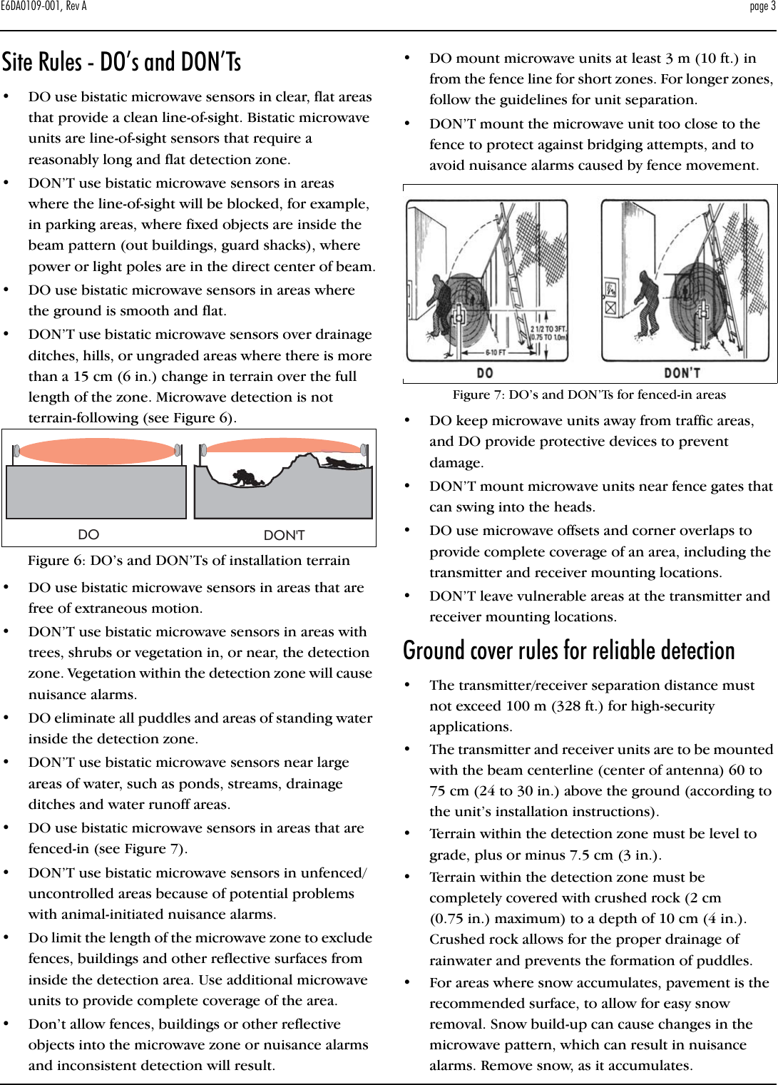
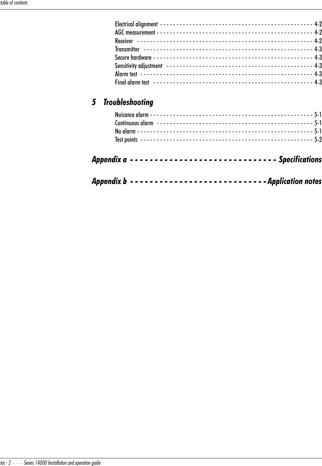
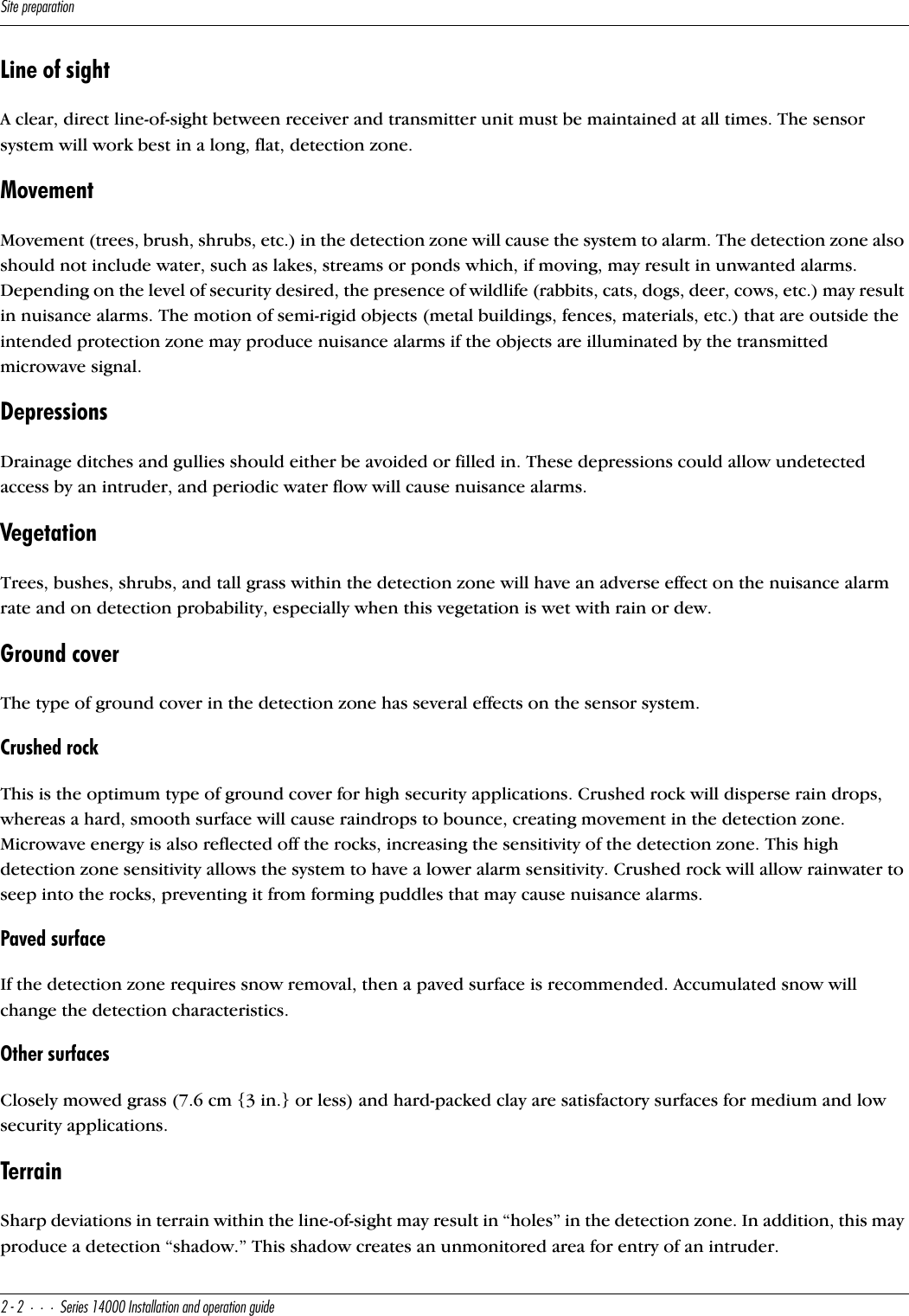
![9^cdQ\\QdY_^]USXQ^YSQ\CUbYUc!$ 9^cdQ\\QdY_^Q^T_`UbQdY_^WeYTU##Installation - mechanicalMounting unitsBoth the transmitter and receiver units must be securely mounted to prevent movement or vibration. Excessive movement or vibration of the units will affect the received signal of the sensor system causing a nuisance alarm. Windy conditions are a potential problem if the units are not mounted properly. Refer to Figure 3-2 for a visual overview of the following instructions.Figure 3-1: Series 14000 microwave unitEnclosureParabolic antennaTamperswitchElectronic PCBOptionalRFI line filterMounting clampsMounting U-bolts](https://usermanual.wiki/Senstar/24000.I5T14100-Installation-and-Operating-Guide/User-Guide-688602-Page-13.png)
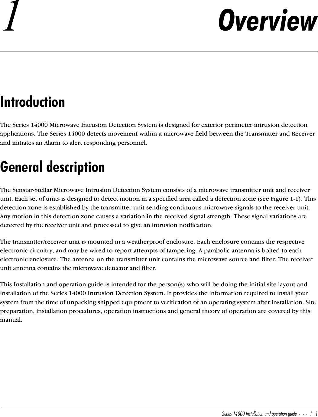
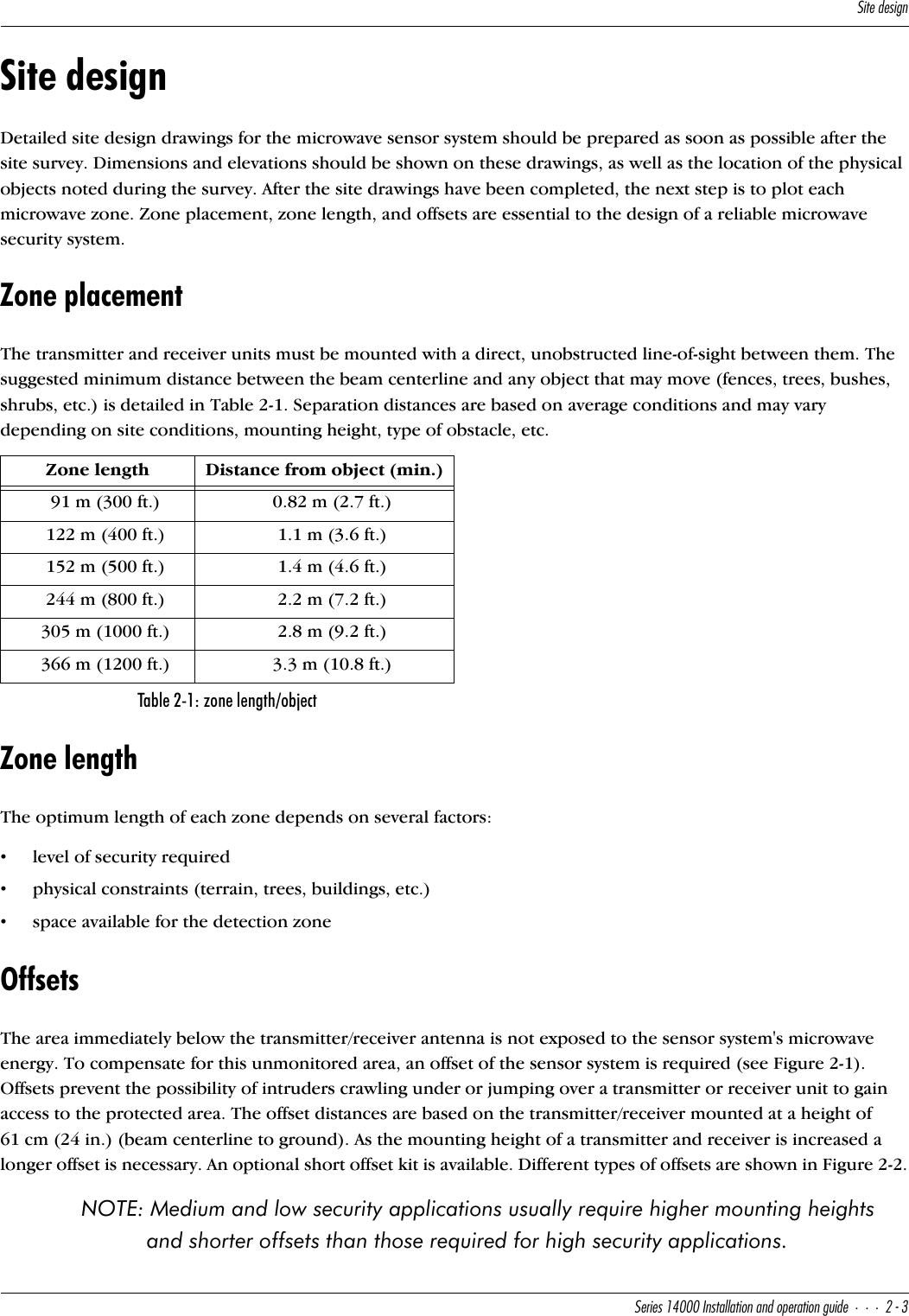
![9^cdQ\\QdY_^]USXQ^YSQ\#$CUbYUc!$ 9^cdQ\\QdY_^Q^T_`UbQdY_^WeYTUSet postThe transmitter and receiver units have been designed to mount on a 9 cm (3 1/2 in.) OD post. A 2.44 m (8 ft.) post is typically used with 91 cm (3 ft.) of the post buried in a concrete footing. Note: Mounting posts are not included.FoundationThe foundation for the mounting posts in normal soil should be at lease 91 cm (3 ft.) deep and 61 cm (2 ft.) in diameter. If soil conditions are such that a non-shifting foundation is questionable, then a larger footing should be considered. In areas where extremely low temperatures may cause frost heaving, use a truncated pyramid base foundation.RebarWhen the foundation concrete cures, there is a possibility of it pulling away from the post, allowing for rotation of the mounting post. Placement of rebar below ground level in the foundation and through the post is suggested to prevent this.Power supply hook-upA weatherproof junction box in the vicinity of each unit's mounting post is the best location for terminating the primary power supply. A double-row terminal block allows this to become a convenient junction box for those lines running back to an alarm reporting panel. Conduit for the power supply junction box should be installed in the foundation as illustrated in Figure 3-2. Be sure to mount the junction box so that it will not interfere with the parabolic antenna or electronic enclosure, and is not in the microwave beam.Figure 3-2: Post installation and unit mountingSeries 14000 unitconcretefootingpowersupplytamperswitchto alarmreportingpanel to transmitteror recieverJunction box detail(Optional)Primary powersource & earthground wireweatherproofjunction boxburied conduitto alarm panel& power supplyrebarthrough pipe9 cm (3.5 in.)steel pipetypically 2.4 m(8 ft.) long91 cm *(3 ft.)61 cm(2 ft.)ground wireground rod*Consult the local construction codes for information about installingconcrete footings in environments where ground freezing occurs.power, groundand alarm wiringin conduitU](https://usermanual.wiki/Senstar/24000.I5T14100-Installation-and-Operating-Guide/User-Guide-688602-Page-14.png)
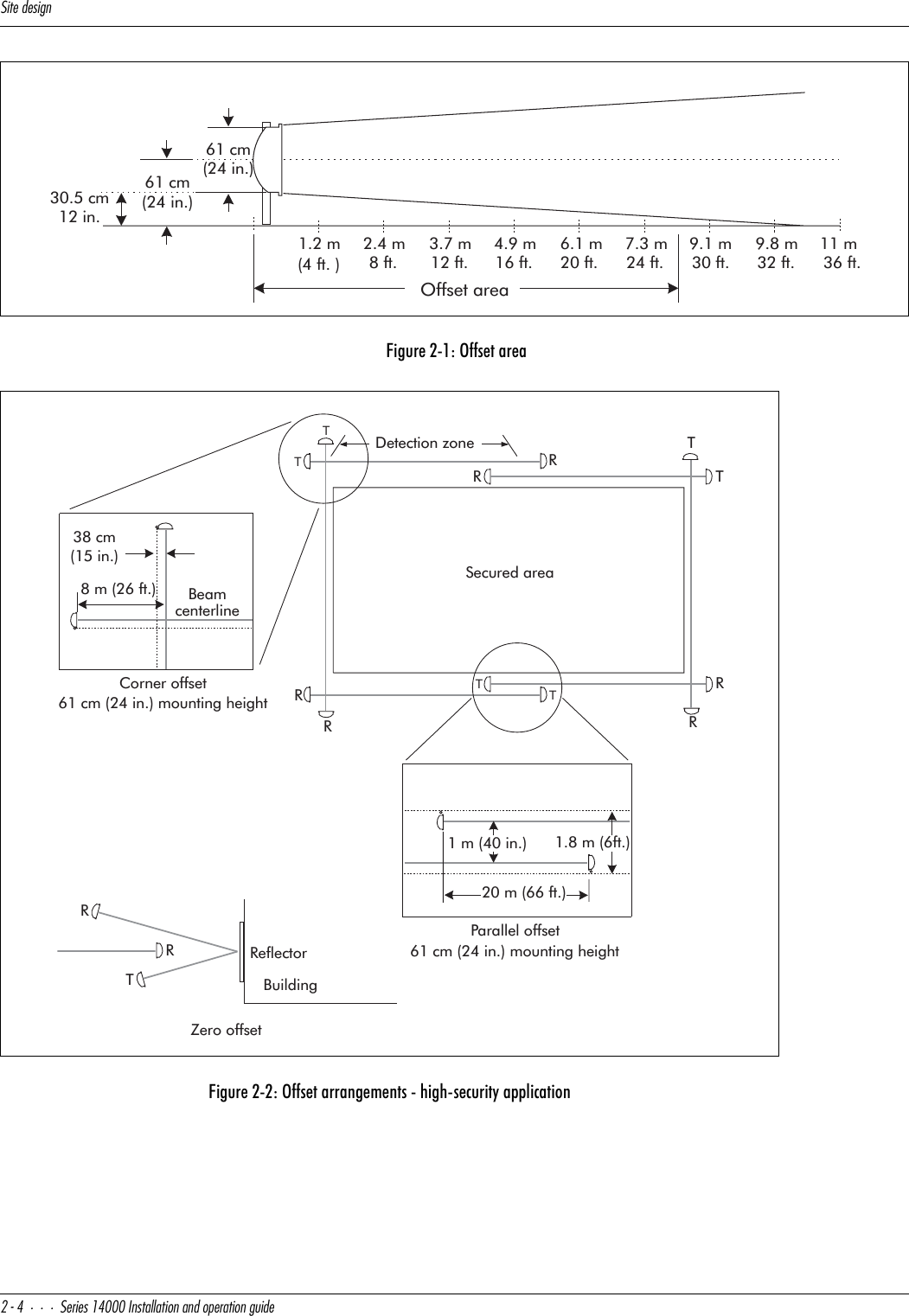
![9^cdQ\\QdY_^]USXQ^YSQ\CUbYUc!$ 9^cdQ\\QdY_^Q^T_`UbQdY_^WeYTU#%Transmitter/ReceiverMount the transmitter and receiver units on their respective posts, using the pipe clamps and hardware provided. The mounting height of the transmitter and receiver units is measured from the center of the parabolic antenna to ground. Refer to Determining mounting height on page 3-6 for the approximate mounting height of the microwave units. For high security applications mount the units at 61 cm (24 in.) centerline to ground.Transmitter/Receiver groundingConnect a ground wire(s) to a properly installed ground rod. Connect the ground wire(s) to the appropriate terminal(s) on the Transmitter/Receiver PCB. (Refer to Figures 3-5 and 3-6 for wiring diagrams of the Transmitter and Receiver circuitry.)NOTE: Senstar-Stellar recommends using a low resistance (5 Ω or less) earth ground connection at each unit. Consult the local electrical codes for additional grounding information.ConduitNOTE: If the RFI filter option is being used, install the RFI filter in each transmitter and receiver enclosure before attaching the conduit.1.9 cm (3/4 in.) flexible conduit should be used to run connections to and from the transmitter/receiver units and power supply junction box. Allow enough slack in this flexible conduit to provide a “drip loop” and vertical movement of ± 46 cm (18 in.).NOTE: Conduit and conduit fittings are not included.RFI Filter (optional)A radio frequency interference (RFI) filter can be connected to all power and signal lines, into and out of each transmitter and receiver unit.Remove the filter cover and position the filter case over the 1.9 cm (3/4 in.) conduit entrance hole. Using a water tight fitting, install the flexible conduit through the transmitter or receiver electronic enclosure. Secure the filter to the transmitter/receiver electronic enclosure using a conduit coupling nut. This coupling nut must be tight to provide mechanical rigidity, a good electrical (ground) contact, and a weather-resistant seal.Align to headRefer to Figure 3-3 for a visual overview of a head to head alignment of the transmitter and receiver units. Physically point the transmitter and receiver toward each other and slightly tighten the clamp nuts so the units will not fall. Loosen the four mounting bolts that secure the parabolic antenna to the electronic enclosure; point the units toward each other and tighten the bolts just enough to keep the antenna from moving.NOTE: This is a preliminary mechanical alignment only. A more precise electrical alignment will be accomplished as part of the Operating instructions procedure.](https://usermanual.wiki/Senstar/24000.I5T14100-Installation-and-Operating-Guide/User-Guide-688602-Page-15.png)
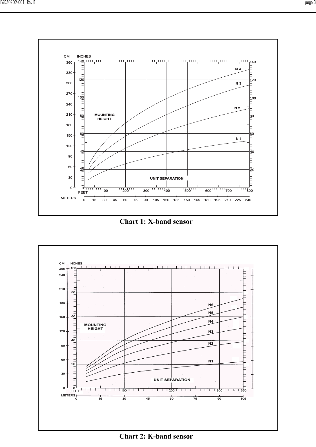
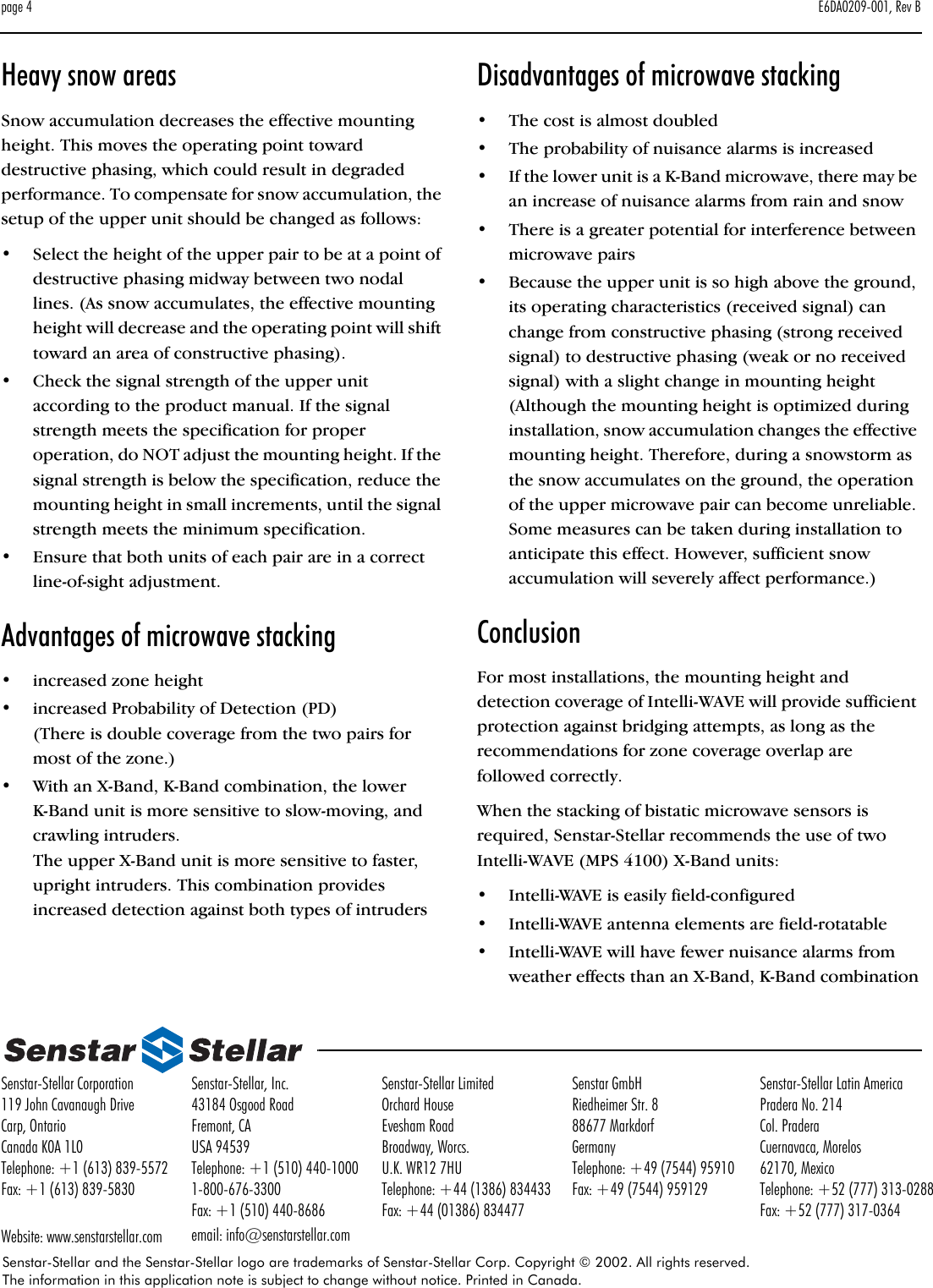
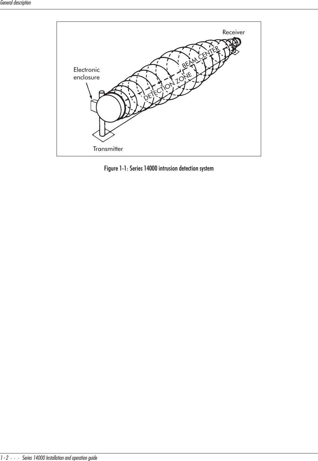
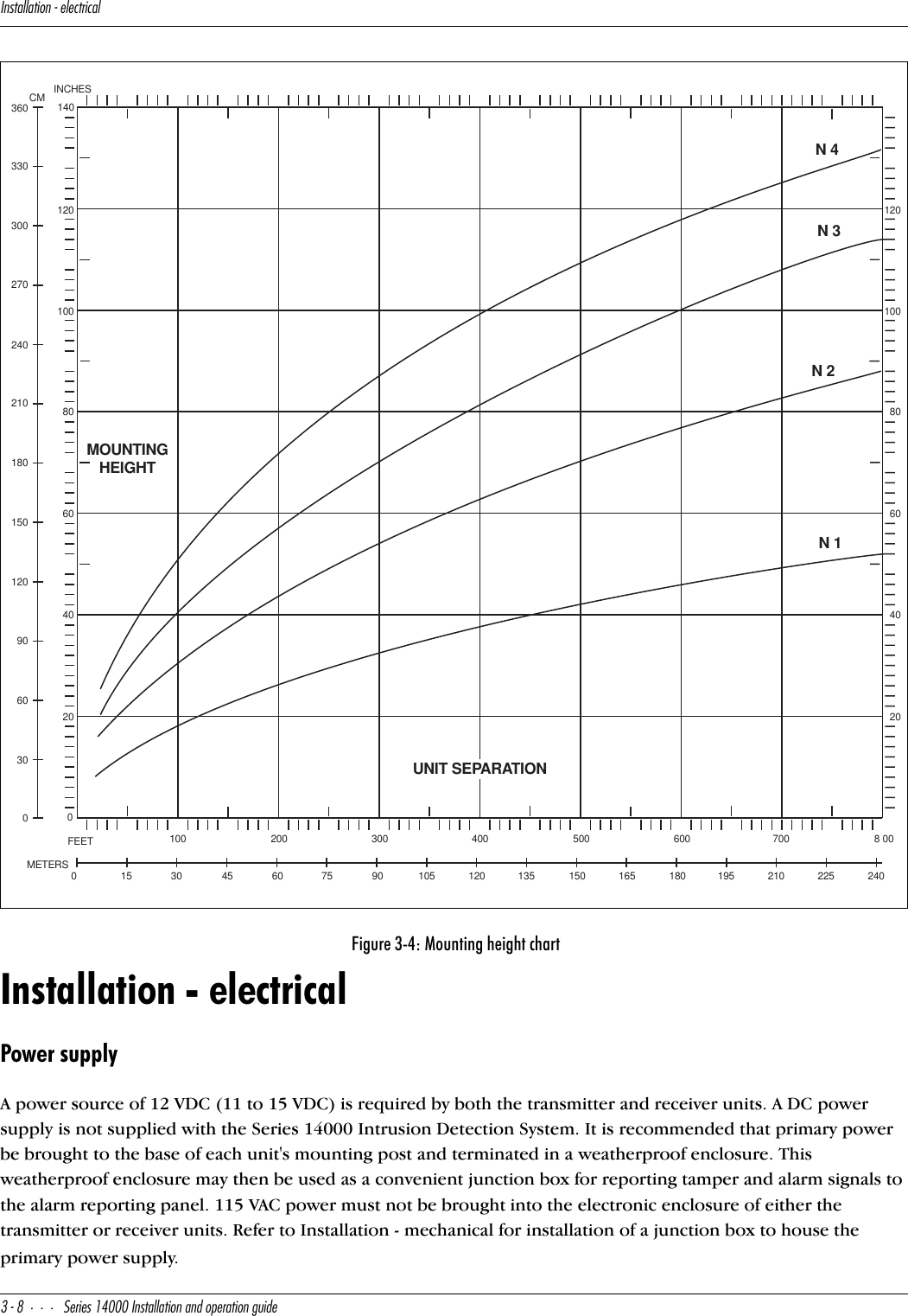
![4UdUb]Y^Y^W]_e^dY^WXUYWXd#&CUbYUc!$ 9^cdQ\\QdY_^Q^T_`UbQdY_^WeYTUDetermining mounting heightThe mounting height chart (Figure 3-4) is used to determine the best theoretical mounting height of the transmitter/receiver units for optimum efficiency of the sensor system. This height chart is intended to furnish a preliminary mounting height only; the final operating height will be determined during electrical alignment and final adjustment.Chart axisThe horizontal axis of the height chart represents the distance between the transmitter and receiver units. The vertical axis represents the mounting height of the transmitter/receiver units from the center of the parabolic antenna to the ground.Figure 3-3: Preliminary alignmentParabolic assemblyattachment flangeTiltRotationAlignmentsightingguide](https://usermanual.wiki/Senstar/24000.I5T14100-Installation-and-Operating-Guide/User-Guide-688602-Page-16.png)
![4UdUb]Y^Y^W]_e^dY^WXUYWXdCUbYUc!$ 9^cdQ\\QdY_^Q^T_`UbQdY_^WeYTU#'Node curvesThe node curves (N1, N2, N3 and N4) represent the pivot point for coordinating distance (horizontal axis) to mounting height (vertical axis). Those mounting height and distance coordinate lines that meet in the area between the node curves should be avoided. Coordinate lines that meet on the node curves are preferred because they will result in higher signal strength at the receiver and a wider fade margin. However, choosing a mounting height at N1 or below will also allow satisfactory system operation.Example:The distance between the transmitter and receiver is 122 m (400 ft.). Locate this distance on the height chart's horizontal axis. Plot a vertical line from this distance point across the node curves. These height measurements represent the best theoretical mounting heights for this example. They are 96 cm (38 in.) or less for the N1 curve and below, 160 cm (63 in.) for the N2 curve, 2 m (82 in.) for the N3 curve, or 2.5 m (99 in.) for the N4 curve.](https://usermanual.wiki/Senstar/24000.I5T14100-Installation-and-Operating-Guide/User-Guide-688602-Page-17.png)
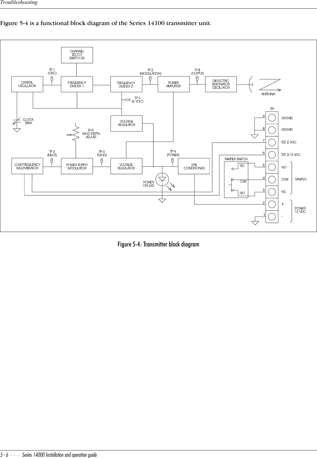
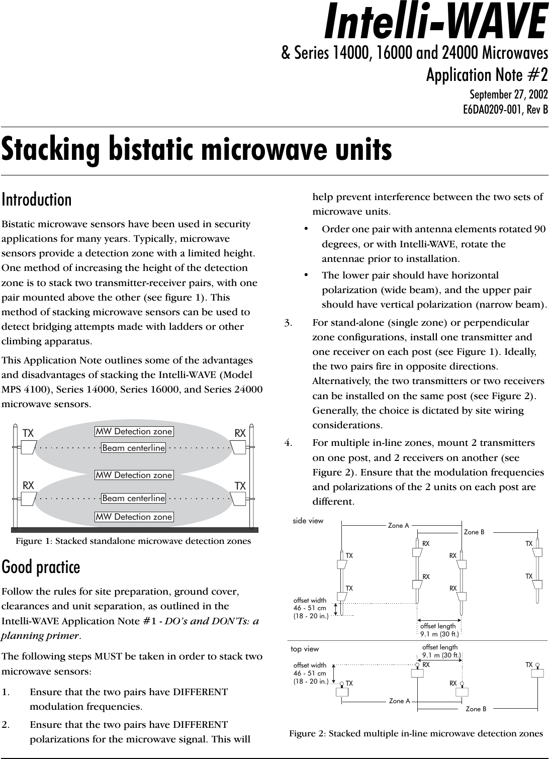
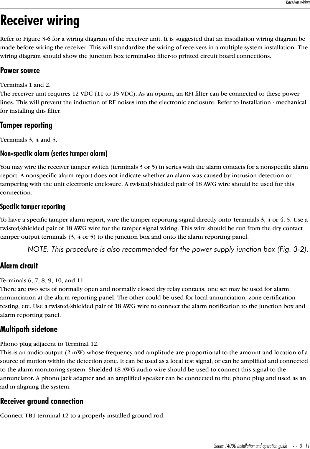
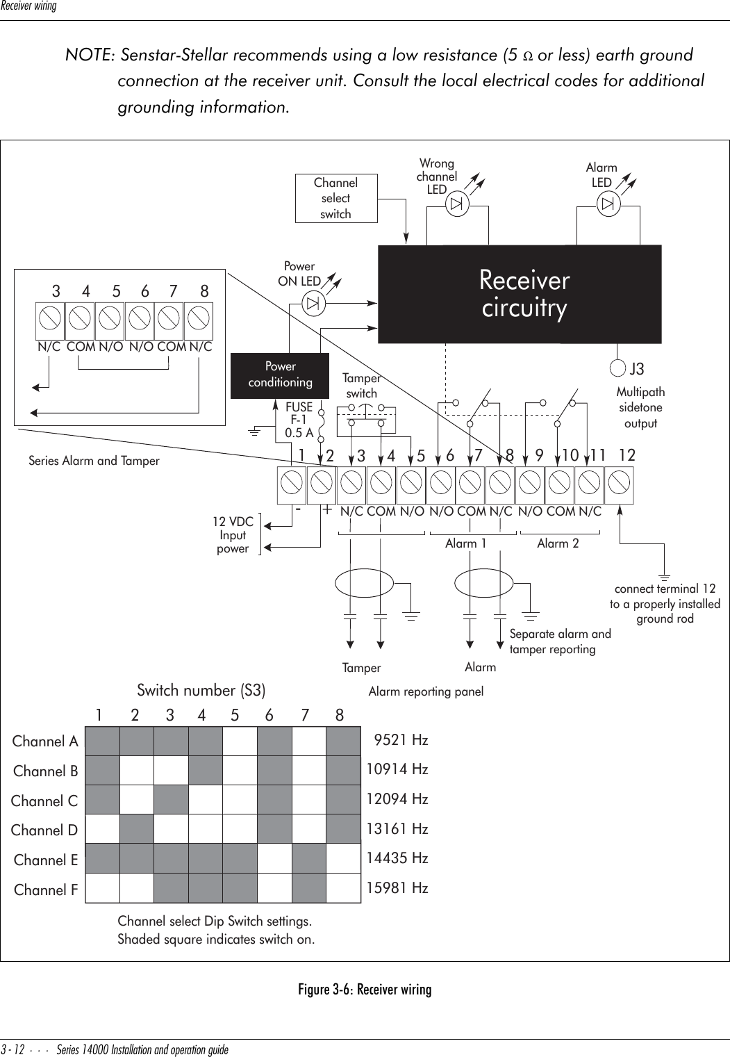
![DbQ^c]YddUbgYbY^WCUbYUc!$ 9^cdQ\\QdY_^Q^T_`UbQdY_^WeYTU#)Transmitter wiringRefer to Figure 3-5 for a wiring diagram of the transmitter unit. It is suggested that an installation wiring diagram be made before wiring the transmitter. This will standardize the wiring of transmitters in a multiple system installation. This installation wiring diagram should show the junction box terminal-to-filter-to printed circuit board connections.Power sourceTerminals 1 and 2.The transmitter requires 12 VDC (11 - 15 VDC) to operate. As an option, an RFI filter can be connected to these power lines. This will prevent the induction of RF noises into the electronic enclosure. Refer to the Installation - mechanical section of the guide for installing this filter.Tamper reportingTo have a specific tamper alarm report, wire the tamper reporting signal directly onto Terminals 3, 4 or 4, 5 and wire power directly to Terminals 1 and 2. Use a twisted/shielded pair of 18 AWG wire for the tamper signal wiring. This wire should be run from the dry contact tamper output terminals (3, 4 or 5) to the junction box and on to the alarm reporting panel.Optional wiringTerminals 3, 4 and 5.The 12VDC power supply to the transmitter may be connected so that when the electronic enclosure is opened, the transmitter is disabled and the receiver goes into constant alarm.Junction Box A tamper switch installed in the power supply junction box may also be wired for tamper reporting. This is done in conjunction with the electronic enclosure tamper wiring and both are connected to the alarm reporting panel.Remote self testTe rm i n al s 6 or 7.The transmitter is capable of providing a test signal that will dynamically test the detection zone to the sensitivity required of that zone. This capability can be remotely activated by applying a +5 to +15 VDC voltage at terminal 6 of the terminal board or by applying a ground to terminal 7 of this terminal board. A shielded 18 AWG wire should be used for this connection regardless of the self test actuation method used.Transmitter ground connectionConnect TB1 terminal(s) 8/9 to a properly installed ground rod.NOTE: Senstar-Stellar recommends using a low resistance (5 Ω or less) earth ground CAUTION: When using one DC power supply to power more than one system, insure the wiring between the power supply and the unit is sufficient to prevent the input voltage at the unit from dropping below 11VDC.](https://usermanual.wiki/Senstar/24000.I5T14100-Installation-and-Operating-Guide/User-Guide-688602-Page-19.png)
![DbQ^c]YddUbgYbY^W#! CUbYUc!$ 9^cdQ\\QdY_^Q^T_`UbQdY_^WeYTUconnection at the transmitter unit. Consult the local electrical codes for additional grounding information.Figure 3-5: Transmitter wiring1234567 89-+12 VDCInputpowerCOM 0VDCN/C N/O 5-15VDCTamper(untamperedcondition)TestsignalenablePower ON LEDPowerconditioningChannelselectswitchTransmittercircuitryFUSEF-1.25 ASeparatetamperreporting12345-+COMN/C N/O-+12 VDCJumperinstalledby user345 6782Switch number (S3)1Channel AChannel BChannel CChannel DChannel EChannel FChannel select Dip Switch settings.Shaded square indicates switch on.9521 Hz10914 Hz12094 Hz13161 Hz14435 Hz15981 HzTamperswitchTamperswitchconnect terminal(s) 8/9to a properly installedground rodPower through tamper switch](https://usermanual.wiki/Senstar/24000.I5T14100-Installation-and-Operating-Guide/User-Guide-688602-Page-20.png)
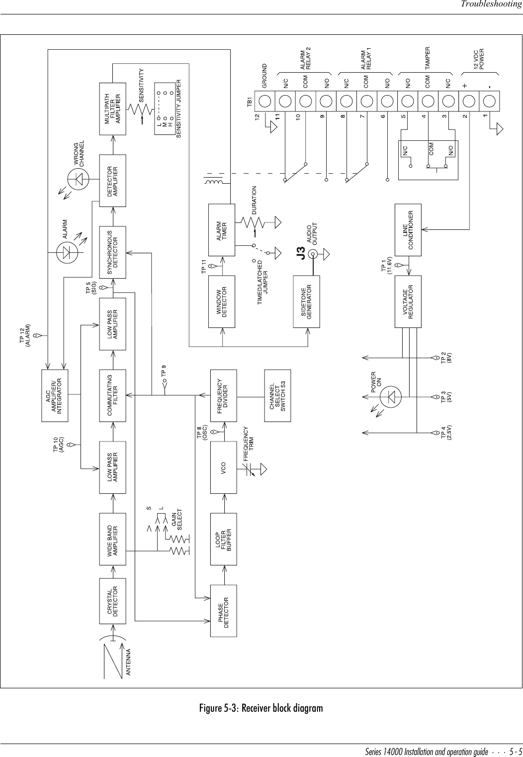
![@bU\Y]Y^QbiSXUS[$"CUbYUc!$ 9^cdQ\\QdY_^Q^T_`UbQdY_^WeYTUSensitivity jumperThe position of the Sensitivity Jumper is determined by the application:•L = Low Security •M = Medium Security•H = High Security(See page 2-1 for definitions of these terms.) This jumper effectively reduces the maximum alarm sensitivity, preventing excessive sensitivity that may result in nuisance alarms.Electrical alignmentAn electrical alignment requires the parabolic antenna of both the transmitter and receiver units to be aimed virtually head-to-head. Refer to Figure 3-3 to verify initial mechanical alignment. Once this initial mechanical alignment is done, a more precise electrical alignment is required.NOTE: The transmitter/receiver units should never be aimed into the ground or off to the side of the detection zone. However, discontinuities in the detection zone may dictate an alignment slightly off head-to-head.AGC measurementAt the receiver, connect a digital voltmeter between TP-10 (+) and TB1-1 (-). This is the automatic gain control (AGC) voltage. After final alignment, as outlined below, the AGC voltage should be between 1.7 and 7.3 VDC. The normal (operating) range of the AGC is 1.8 - 3.2 VDC. Put the SHORT-LONG jumper in the LONG position to increase the AGC voltage. Put the SHORT-LONG jumper in the SHORT position to decrease the AGC voltage.ReceiverSlowly move the receiver up and down the post while monitoring the receiver AGC voltage. Once a maximum AGC voltage is obtained, rotate the receiver until maximum AGC is obtained on this axis. Tilt the receiver parabolic antenna up and down, again adjusting for maximum AGC voltage.Note: The AGC response time is faster when the timed-latched jumper (white wire) is in the “latched” position.TransmitterContinue to monitor the AGC voltage at the receiver while moving the transmitter in all three axes as described for the receiver, until maximum AGC voltage is obtained.](https://usermanual.wiki/Senstar/24000.I5T14100-Installation-and-Operating-Guide/User-Guide-688602-Page-24.png)
![@bU\Y]Y^QbiSXUS[CUbYUc!$ 9^cdQ\\QdY_^Q^T_`UbQdY_^WeYTU$#Final alignmentBefore securing the mounting hardware, repeat the transmitter and receiver unit electrical alignment steps for obtaining maximum AGC reading on all rotational axes.Secure hardwareSecure the mounting nuts and parabolic-to-enclosure bolts. Ensure the AGC voltage remains high after the hardware is tightened. Put the timed-latched jumper (white wire) into the “timed” position.Sensitivity adjustmentBefore beginning a sensitivity adjustment, make sure the receiver “ALARM” LED is not lit. Connect an ohmmeter between TB1 - terminals 10 and 11. It will read less than 0.5 ohms when the system is operational (armed) and infinity when the unit is in alarm. Leave the ohmmeter connected.Alarm testA preliminary alarm test requires walking across the detection zone to ensure the unit goes into alarm (“ALARM” LED lit, ohmmeter to infinity). If it does not, adjust the sensitivity potentiometer (R55) clockwise; then walk test the zone again. An alarm report should normally occur before a line of sight between the transmitter and receiver units is broken by the walker.Final alarm testDetermine the level of security sensitivity desired and then use the following parameters for ensuring that the level desired is present.Note: Make sure the sensitivity jumper (L-M-H) is in the correct position for your application.Low security - walk across detection zone in every area intrusion concern is present. Adjust R55 for consistent detection.Medium security - crawl on hands and knees in all detection zone areas of intrusion concern. Adjust R55 for consistent detection.High security - pull the metal sphere (see High security zone) through the zone; pull often enough to give confidence that the zone has the sensitivity you want.](https://usermanual.wiki/Senstar/24000.I5T14100-Installation-and-Operating-Guide/User-Guide-688602-Page-25.png)
![@bU\Y]Y^QbiSXUS[$$CUbYUc!$ 9^cdQ\\QdY_^Q^T_`UbQdY_^WeYTUHigh security zoneAdjustment for a typical high security application requires the detection of a prone human crawling through the detection zone with the length of the body parallel to the line of sight. A 30.5 cm (12 in.) metal sphere (see tools on page 3-2) represents approximately the same target to the microwave sensor. When adjusting the sensitivity to high security specifications, slowly (2.4 cm {1 in.} per second or faster) pull the sphere through the zone (perpendicular to the line of sight) approximately every 3 m (10 ft.) and adjust the sensitivity potentiometer (R55) until repeatable detection is obtained.NOTE: Dragging the sphere in the offset area is not necessary.](https://usermanual.wiki/Senstar/24000.I5T14100-Installation-and-Operating-Guide/User-Guide-688602-Page-26.png)