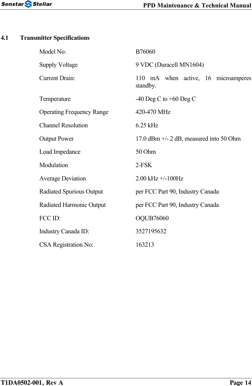
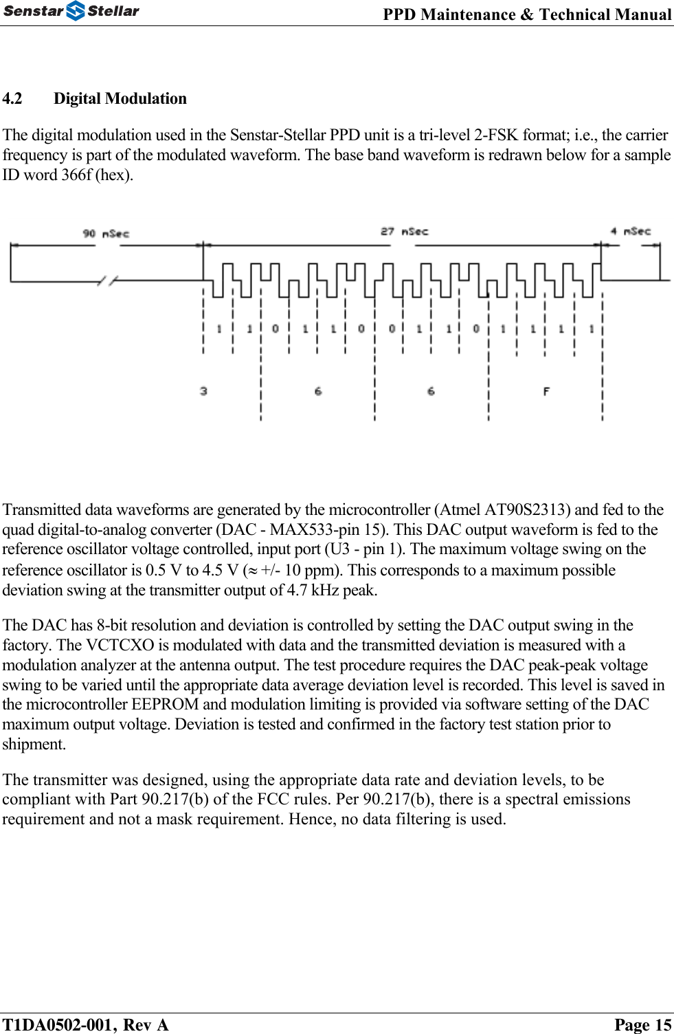
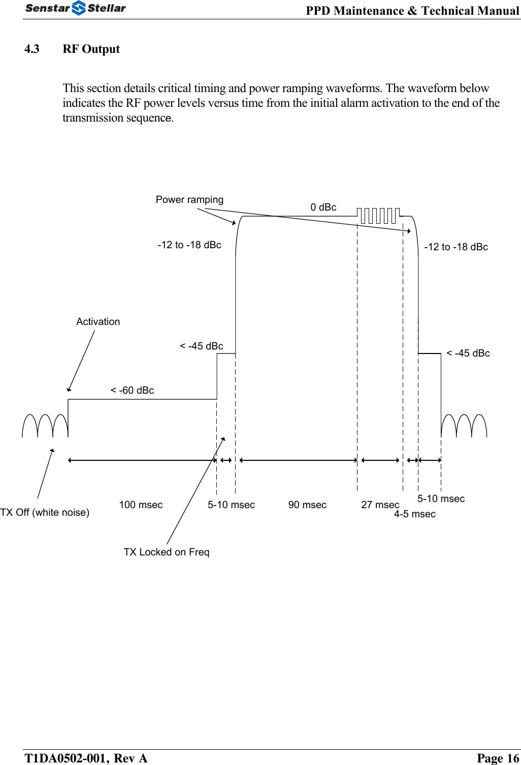
Senstar B76060 Personal Alarm Transmitter User Manual Personal Protection Device PPD
Senstar Corporation Personal Alarm Transmitter Personal Protection Device PPD
UserManual.wiki
>
Senstar
>
B76060 User Manual
Manual
Navigation menu
Upload a User Manual
Namespaces
Wiki Guide
HTML
PDF
Info
Views
User Manual
Discussion / Help
Navigation
![PPD Maintenance & Technical Manual 2.0 OPERATIONS AND MAINTENANCE 2.1 Operating Instructions 2.1.1 Wearing the PPD Always wear the PPD on the belt in a location that permits easy access to the push button or pull-pin. It is recommended the unit be used with the optional carrying holster for added protection. Insert the PPD into the pouch with the logo-end first taking care to line up the button with the hole in the pouch. The significance of this is to avoid covering the antenna (mounted under the logo) with your hand when reaching down to press the activation button. The performance of the unit is not degraded if worn under clothing. If the unit is equipped with an external antenna, do not wrap the antenna around the PPD – leave it hang vertically from the end of the PPD. The leather holster is equipped with a loop over the top of the unit to secure the PPD. To remove the PPD from the holster, unsnap the retaining loop and pull on the end of the PPD (in new holsters, this pulling action may need to be accompanied by a push on the step of the housing that is exposed in the push-button area). The holster is secured to the belt using an integral belt loop. This loop is secured to the holster using polarized snaps. These snaps are polarized such that they can only be removed by prying the snaps open with the fingers positioned under the snap end of the belt loop. This takes a little practice. The purpose of the polarized snaps is to prevent the unit from being pulled off the belt by force. To close the belt loop snaps, reverse the motion used to open them. 2.1.2 Activation The PPD is activated by pressing the red button on the outside of the unit. For optimum reliability, feel for the raised centering dot on the button before pressing. The unit transmits a unique ID code once each time the PPD is activated. It takes approximately one quarter (.25) of a second for the transmitter to complete the alarm sequence once the unit is activated. The alarm will be detected by the computer monitor within .5 seconds of activation. Low Battery Detection (Automatic Activation) The PPD continuously monitors its battery voltage. If the battery voltage drops below a pre-defined threshold, the unit automatically emits a low battery transmission to inform the head end software that a particular ID transmitter has a low battery. [NOTE: This requires that your facility has purchased the OPTIONAL low battery detection software.] The PPD is still capable of transmitting ten times after reaching the low battery threshold. After the automatic low battery transmission has occurred, the PPD will append a low battery transmission after each subsequent alarm activation to remind the head end operator. Units in low battery mode should be taken out of service. Battery replacement is a maintenance function. T1DA0502-001, Rev A Page 5](https://usermanual.wiki/Senstar/B76060/User-Guide-575698-Page-5.png)
![PPD Maintenance & Technical Manual DON’T Don’t - Submerge the PPD in water or expose it to pounding rain. Don’t - Cover the unit with your hand or metal objects while transmitting. Don’t - Wear or store the PPD without the pull-pin completely inserted. Don’t - Replace batteries unless you are a certified maintenance technician. Don’t - Remove the marking labels on the transmitter. Don’t - Drop or otherwise abuse the transmitter. Don’t - Leave the transmitter unattended in the “tilted” position (Man-down units only). 2.3 Operator Maintenance and Cleaning There are no operator-serviceable components or adjustments on the PPD. If the unit becomes soiled, wipe with a damp (not dripping) cloth or paper towel. Do not use other solvents or cleaning agents on the transmitter housing. If the carrying pouch becomes saturated with moisture, obtain a new pouch since this can potentially impact accuracy (Flare systems only). Battery replacement is a maintenance function due to the fact that the low battery detection software must be reset. Battery replacement is discussed elsewhere in this manual. If included with your system, the PPD outer protective case (carrying pouch) is made from genuine leather. It should be cleaned and cared for as for any leather product (e.g., periodically clean and moisturize with saddle soap or other leather cleaner). Remove the PPD from the leather case before cleaning to avoid contacting the PPD itself with the cleaning solution. 2.4 Accessories Senstar-Stellar PPD Carrying Pouch Programming Board and Software (Sets Transmitter ID and Man-Down Programmable Options) Battery Cover TorxTM Security Driver, Size T8 – Not Included (McMaster Carr #7233A61) Man-Down Module - [Optional] Pull Pin & Lanyard - [Optional] T1DA0502-001, Rev A Page 7](https://usermanual.wiki/Senstar/B76060/User-Guide-575698-Page-7.png)
![PPD Maintenance & Technical Manual 3.0 BATTERY SPECIFICATIONS AND REPLACEMENT 3.1 Battery Life Specification and Considerations DC Power Source +9V nominal battery Duracell, MN1604, Alkaline DC Current Consumption 110 mA +/- 20 mA (during full transmission) The end of life of the PPD is defined as the point at which the battery voltage drops to 7.0 VDC. At this voltage, the transmitter will still transmit reliably ten times at low temperatures. When the transmitter detects voltages at or below this level, it automatically emits a unique code identifying that it is in low battery mode. The head end software will only recognize this event if it has been purchased with the low battery detection option. The transmitter has been designed and tested to comply with the following battery life specification: One year of continuous operation, transmitted three times per day, operated at room temperature, with no optional features included. Under normal operating conditions, the battery life will exceed more than one year. Factors affecting battery life include: A) Operating Temperature Low temperatures will decrease battery output voltage and, as a result, shorten the battery life. It may be observed that a unit operates correctly indoors (at room temperature), but will experience sufficient voltage drop when used outdoors (in cold environment) for activating the automatic low battery detection transmission. If this occurs, take the unit out of service immediately. [NOTE: Senstar-Stellar PPD transmitters have been independently tested and shown to achieve over 3,000 transmissions at –40 degrees Celsius before the low battery threshold was observed]. B) Number of Activations Every time the transmitter is activated, it draws 110 mA for a short period. This consumes battery capacity. Under ideal conditions (with a new battery at room temperature), independent tests have shown the PPD transmitter to achieve over 30,000 transmissions. T1DA0502-001, Rev A Page 8](https://usermanual.wiki/Senstar/B76060/User-Guide-575698-Page-8.png)
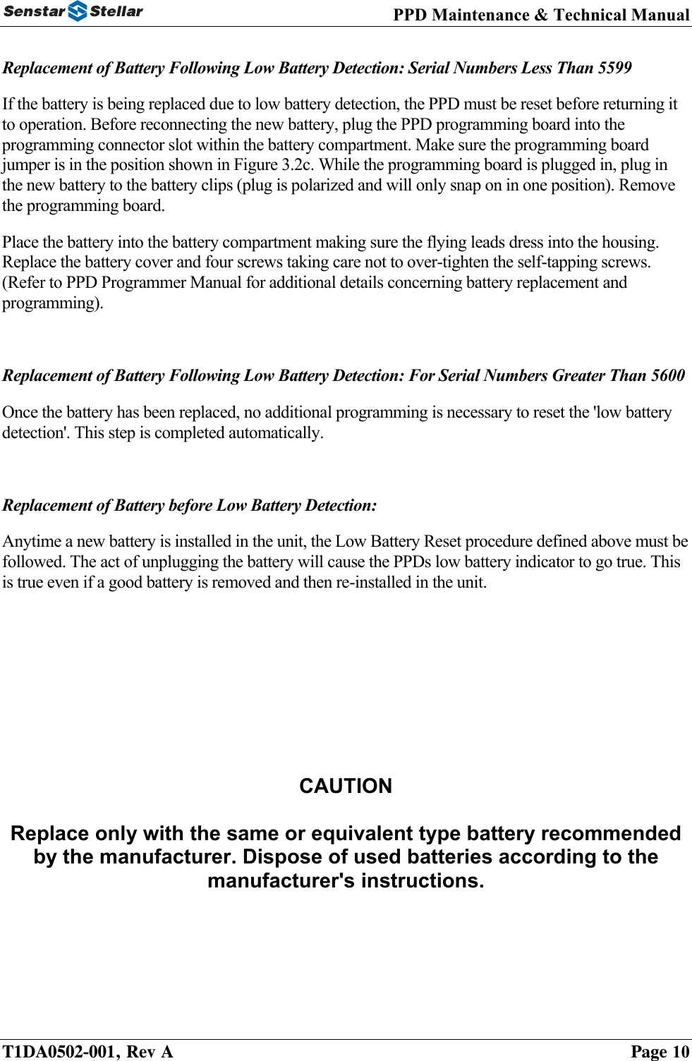
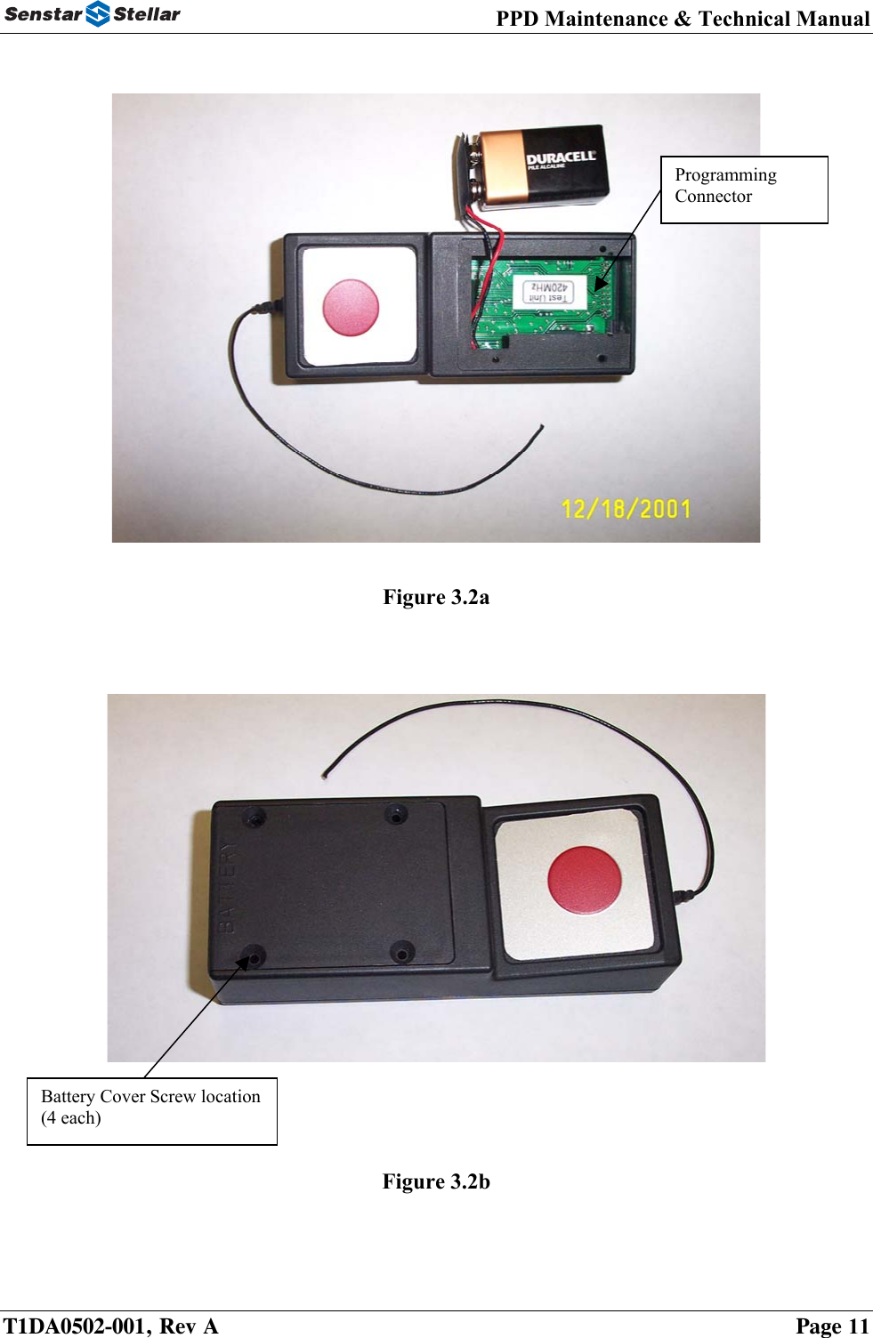
![PPD Maintenance & Technical Manual C) Optional Features (Man-Down) The man-down feature reduces battery life due to the increased standby current drain and due to the fact that the unit will “wake up” every time it is tilted and start emitting tones. The number of times the unit is tilted is a variable beyond the manufacturer’s control, so a battery life specification is more difficult to define. The battery life is defined as follows for the Man-Down option: One year of continuous operation at room temperature assuming no manual activations or automatic activations (due to tilt) during the year. Following the one year under these conditions, the unit will be capable of automatically activating due to a tilt or manually activating using the pushbutton. D) Hours of Standby Operation The standard transmitter (no options) consumes a steady current drain of 16 microamperes. At this rate, the PPD consumes 25% of its original battery capacity merely by having the battery installed in the unit. Furthermore, commercial alkaline batteries typically degrade 10% to 15% per year in (this is the effect of so-called “shelf life” on battery capacity). If the PPD is to be stored on a shelf for several years, remove the battery or expect to replace the battery before putting that PPD back in service. The man-down option causes the standby current of the transmitter to increase to 50 microamperes nominally. One year of standby operation will effectively consume the battery capacity of a 9 Volt alkaline cell. 3.2 Battery Replacement Currently, 2 types of transmitters exist. 1] Transmitters requiring additional programming to reset the 'low battery detection' warning and 2] Transmitters requiring NO additional programming once the battery has been replaced. The serial numbers on the back of the transmitter (PPD) is used to differentiate between the two (2) model types. Transmitters carrying serial numbers below 5599 will require additional programming to reset the 'low battery detection' after the battery is replaced. Transmitters carrying serial numbers above 5600 do not require additional programming. Once the battery has been replaced, the reset is automatically performed. Battery Removal: The battery is accessed by removing the battery cover (refer to Figures 3.2a and 3.2b below). Always open the battery cover at a workstation equipped with electrostatic discharge (ESD) protection. Static sensitive components are exposed when the battery cover is removed. Removal requires a TorxTM security driver, Size T8 (McMaster Carr #7233A61). Remove the four screws. Remove the battery from the battery compartment by gently tapping the transmitter case against the palm of the hand while the battery cover is removed. The battery will fall into your hand, retained by the flying leads of the battery clip. Carefully unsnap the battery clip and discard the old battery. T1DA0502-001, Rev A Page 9](https://usermanual.wiki/Senstar/B76060/User-Guide-575698-Page-9.png)