Senstar B76060 Personal Alarm Transmitter User Manual Personal Protection Device PPD
Senstar Corporation Personal Alarm Transmitter Personal Protection Device PPD
Senstar >
Manual

PPD Maintenance & Technical Manual
Personal Protection Device (PPD)
Maintenance & Technical Manual
T1DA0502-001, Rev. A
January 29, 2004
Company
Name:
Senstar-Stellar
Corporation
Senstar-Stellar Senstar- Stellar Ltd. Senstar GmbH Senstar-Stellar Latin
America
Address: 119 John Cavanaugh
Dr.
43184 Osgood Rd. Orchard House,
Evesham Rd.
Reidheimer Str. 8 Pradera No. 214,
Col. Pradera
Carp, Ontario Fremont, CA Broadway, Worc. 88677 Markdorf Cuernavaca,
Morelos
Canada K0A 1L0 USA 94539 U.K. WR127HU Germany 62170, Mexico
Phone: +1 (613) 839-5572 +1 (510) 440-1000 +44 (1386) 834433 +49 (7544) 95910 +52 (777) 313-0288
Toll Free: 1-800-676-3300
Fax: +1 (613) 839-5830 +1 (510) 440-8686 +44 (1386) 834477 +49 (7544) 959129 +52 (777) 317-0364
Website: www.senstarstellar.com
E-mail: info@senstarstellar.com
All material, including technical data, designs, knowledge, and ideas contained in this
document are considered proprietary, and the exclusive property of Senstar-Stellar
Corporation, and shall not be used, disclosed, reproduced, or transmitted in any form or by
any means, electrical or mechanical, including photocopying, recording, or by any information
storage or retrieval system, without permission in writing from Senstar-Stellar Corporation.
T1DA0502-001, Rev A Page 1

PPD Maintenance & Technical Manual
Senstar-Stellar Life Safety Division
22611 Markey Court, Unit 110
Sterling, VA, USA 20166-6903
Tel: 703.421.2086 Fax: 703.421.2149
Revision History
January, 2000 A76321 Draft A.0 First Draft
12/21/2001 A76321 Rev 1.0 Initial Release
02/09/2002 A76321 Rev 1B Update Programmer Jumper Layout of OLD
programmer
04/09/2002 A76321 Rev 1C Update Programming Jumper Layout for new
programmer
08/25/2002 A76321 Rev1D Section 3.2 reflects release of new PPD transmitter
29/01/2004 T1DA0502-001 Rev A Company name and Logo change, document
number change, formatting changes
T1DA0502-001, Rev A Page 2

PPD Maintenance & Technical Manual
TABLE of CONTENTS
1.0 INTRODUCTION............................................................................................................... 4
2.0 OPERATIONS AND MAINTENANCE........................................................................... 5
2.1 Operating Instructions.................................................................................................... 5
2.1.1 Wearing the PPD....................................................................................................... 5
2.1.2 Activation................................................................................................................... 5
2.1.3 Testing........................................................................................................................ 6
2.2 Do’s and Don’ts................................................................................................................ 6
2.3 Operator Maintenance and Cleaning ............................................................................ 7
2.4 Accessories........................................................................................................................ 7
3.0 BATTERY SPECIFICATIONS AND REPLACEMENT .............................................. 8
3.1 Battery Life Specification and Considerations ............................................................. 8
3.2 Battery Replacement ....................................................................................................... 9
4.0 PPD THEORY OF OPERATION................................................................................... 13
4.1 Transmitter Specifications............................................................................................ 14
4.2 Digital Modulation......................................................................................................... 15
4.3 RF Output ...................................................................................................................... 16
4.4 PPD Detailed Hardware Description........................................................................... 17
4.4.1 Synthesizer............................................................................................................... 17
4.4.2 Voltage Controlled Oscillator (VCO).................................................................... 18
4.4.3 VCO Buffer Amplifier............................................................................................ 18
4.4.4 Reference Oscillator (VCTCXO)........................................................................... 18
4.4.5 Driver Stage............................................................................................................. 19
4.4.6 Band Pass Interstage Filter.................................................................................... 19
4.4.7 Final Amplifier........................................................................................................ 19
T1DA0502-001, Rev A Page 3

PPD Maintenance & Technical Manual
1.0 INTRODUCTION
The Senstar-Stellar personal protection device (PPD) is a body-worn radio transmitter, which
emits an alert signal when activated. The PPD is intended to be worn on the belt of the user.
When used in a facility equipped with the Senstar-Stellar FlashTM or FlareTM system, the
transmitter notifies security staff an alarm transmission has occurred and reports the location of
the user on a computerized map of the facility (Flare ONLY). Each PPD is identified by a unique
ID code. The PPD is activated by pressing the red button on the front of the unit. The unit may
also be equipped with an optional 'man-down' module and/or a tamper detection lanyard.
The PPD is activated by pressing the red button on the front of the unit. Optional activation
methods include removing a lanyard/pull-pin assembly and an automatic “man-down” mode that
is initiated based on the tilt angle of the transmitter.
This manual contains operating instructions for the PPD unit, care and maintenance instructions,
as well as a detailed theory of operations.
T1DA0502-001, Rev A Page 4

PPD Maintenance & Technical Manual
2.0 OPERATIONS AND MAINTENANCE
2.1 Operating Instructions
2.1.1 Wearing the PPD
Always wear the PPD on the belt in a location that permits easy access to the push button or pull-
pin. It is recommended the unit be used with the optional carrying holster for added protection.
Insert the PPD into the pouch with the logo-end first taking care to line up the button with the
hole in the pouch. The significance of this is to avoid covering the antenna (mounted under the
logo) with your hand when reaching down to press the activation button. The performance of the
unit is not degraded if worn under clothing. If the unit is equipped with an external antenna, do
not wrap the antenna around the PPD – leave it hang vertically from the end of the PPD.
The leather holster is equipped with a loop over the top of the unit to secure the PPD. To remove
the PPD from the holster, unsnap the retaining loop and pull on the end of the PPD (in new
holsters, this pulling action may need to be accompanied by a push on the step of the housing
that is exposed in the push-button area). The holster is secured to the belt using an integral belt
loop. This loop is secured to the holster using polarized snaps. These snaps are polarized such
that they can only be removed by prying the snaps open with the fingers positioned under the
snap end of the belt loop. This takes a little practice. The purpose of the polarized snaps is to
prevent the unit from being pulled off the belt by force. To close the belt loop snaps, reverse the
motion used to open them.
2.1.2 Activation
The PPD is activated by pressing the red button on the outside of the unit. For optimum
reliability, feel for the raised centering dot on the button before pressing. The unit transmits a
unique ID code once each time the PPD is activated. It takes approximately one quarter (.25) of a
second for the transmitter to complete the alarm sequence once the unit is activated. The alarm
will be detected by the computer monitor within .5 seconds of activation.
Low Battery Detection (Automatic Activation)
The PPD continuously monitors its battery voltage. If the battery voltage drops below a pre-
defined threshold, the unit automatically emits a low battery transmission to inform the head end
software that a particular ID transmitter has a low battery. [NOTE: This requires that your
facility has purchased the OPTIONAL low battery detection software.] The PPD is still capable
of transmitting ten times after reaching the low battery threshold. After the automatic low battery
transmission has occurred, the PPD will append a low battery transmission after each subsequent
alarm activation to remind the head end operator. Units in low battery mode should be taken out
of service. Battery replacement is a maintenance function.
T1DA0502-001, Rev A Page 5

PPD Maintenance & Technical Manual
Pull-Pin Option
Pull-pin version PPDs are activated by completely removing the pull-pin from its jack on the top
of the PPD. The pull-pin is equipped with a flexible lanyard to make activation easier. The
lanyard can be looped over a belt clip to force the PPD to alarm if it is ever removed from the
wearer. Re-inserting the pull-pin in does not prevent the transmitter from sending the alert signal.
Always return the pull-pin to its mating plug in the PPD housing so that the unit is armed and to
prevent the pull-pin from becoming lost. Do not cover the PPD with your hand when activating –
simply press the button or remove the pull-pin.
Man-Down Option
If the PPD is equipped with a man-down option, it will automatically activate if the unit remains
tilted too long. The default length of time of continuous tilt is 15 seconds. Consult the factory if
you wish to alter this time period – it can be programmed by the system administrator at your
facility. The default tilt angle threshold is 45 degrees. Consult the factory if you wish to alter this
tilt angle – it can be programmed by the system administrator at your facility. To help prevent
false alarms, the unit emits a warning tone once the 15 second timer begins counting. If the unit
is returned to vertical, the warning tone is silenced and the timer is reset. If the unit remains tilted
continuously for 15 seconds, the PPD will automatically activate an alarm transmission. The
default mode is to transmit one time only following a man-down condition. Consult the factory if
you wish the unit to continue to transmit – it can be programmed by the system administrator at
your facility.
2.1.3 Testing
Senstar-Stellar recommends staff test the PPD at the beginning of each shift. Your facility
administrator will develop a procedure for you to warn the security staff that a test transmission
is under way and for the security staff to communicate to you that the unit has passed. Follow
their established procedures. The battery is designed to support testing the basic PPD (no man-
down option) three times per day for one year before battery replacement is required.
2.2 Do’s and Don’ts
DO:
DO - Always wear the PPD on your belt.
DO - Always position the PPD on your belt such that the red button or pull-pin is accessible.
DO - When activating the alarm, feel for the bump in the center of the red button before pressing.
DO - Always wear the transmitter with the logo face facing away from your body.
DO - If your PPD fails to transmit upon activation, turn the unit into maintenance immediately.
DO - If you accidentally press the red button or remove the pull-pin, contact security
immediately to report the false alarm.
T1DA0502-001, Rev A Page 6

PPD Maintenance & Technical Manual
DON’T
Don’t - Submerge the PPD in water or expose it to pounding rain.
Don’t - Cover the unit with your hand or metal objects while transmitting.
Don’t - Wear or store the PPD without the pull-pin completely inserted.
Don’t - Replace batteries unless you are a certified maintenance technician.
Don’t - Remove the marking labels on the transmitter.
Don’t - Drop or otherwise abuse the transmitter.
Don’t - Leave the transmitter unattended in the “tilted” position (Man-down units only).
2.3 Operator Maintenance and Cleaning
There are no operator-serviceable components or adjustments on the PPD. If the unit becomes
soiled, wipe with a damp (not dripping) cloth or paper towel. Do not use other solvents or
cleaning agents on the transmitter housing. If the carrying pouch becomes saturated with
moisture, obtain a new pouch since this can potentially impact accuracy (Flare systems only).
Battery replacement is a maintenance function due to the fact that the low battery detection
software must be reset. Battery replacement is discussed elsewhere in this manual.
If included with your system, the PPD outer protective case (carrying pouch) is made from
genuine leather. It should be cleaned and cared for as for any leather product (e.g., periodically
clean and moisturize with saddle soap or other leather cleaner). Remove the PPD from the
leather case before cleaning to avoid contacting the PPD itself with the cleaning solution.
2.4 Accessories
Senstar-Stellar PPD Carrying Pouch
Programming Board and Software (Sets Transmitter ID and Man-Down Programmable Options)
Battery Cover TorxTM Security Driver, Size T8 – Not Included
(McMaster Carr #7233A61)
Man-Down Module - [Optional]
Pull Pin & Lanyard - [Optional]
T1DA0502-001, Rev A Page 7

PPD Maintenance & Technical Manual
3.0 BATTERY SPECIFICATIONS AND REPLACEMENT
3.1 Battery Life Specification and Considerations
DC Power Source +9V nominal battery
Duracell, MN1604, Alkaline
DC Current Consumption 110 mA +/- 20 mA (during full transmission)
The end of life of the PPD is defined as the point at which the battery voltage drops to 7.0 VDC. At
this voltage, the transmitter will still transmit reliably ten times at low temperatures. When the
transmitter detects voltages at or below this level, it automatically emits a unique code identifying that
it is in low battery mode. The head end software will only recognize this event if it has been purchased
with the low battery detection option.
The transmitter has been designed and tested to comply with the following battery life specification:
One year of continuous operation, transmitted three times per day, operated at room temperature,
with no optional features included.
Under normal operating conditions, the battery life will exceed more than one year.
Factors affecting battery life include:
A) Operating Temperature
Low temperatures will decrease battery output voltage and, as a result, shorten the battery life. It may
be observed that a unit operates correctly indoors (at room temperature), but will experience sufficient
voltage drop when used outdoors (in cold environment) for activating the automatic low battery
detection transmission. If this occurs, take the unit out of service immediately.
[NOTE: Senstar-Stellar PPD transmitters have been independently tested and shown to achieve over
3,000 transmissions at –40 degrees Celsius before the low battery threshold was observed].
B) Number of Activations
Every time the transmitter is activated, it draws 110 mA for a short period. This consumes battery
capacity. Under ideal conditions (with a new battery at room temperature), independent tests have
shown the PPD transmitter to achieve over 30,000 transmissions.
T1DA0502-001, Rev A Page 8

PPD Maintenance & Technical Manual
C) Optional Features (Man-Down)
The man-down feature reduces battery life due to the increased standby current drain and due to the
fact that the unit will “wake up” every time it is tilted and start emitting tones. The number of times
the unit is tilted is a variable beyond the manufacturer’s control, so a battery life specification is more
difficult to define. The battery life is defined as follows for the Man-Down option:
One year of continuous operation at room temperature assuming no manual activations or automatic
activations (due to tilt) during the year. Following the one year under these conditions, the unit will be
capable of automatically activating due to a tilt or manually activating using the pushbutton.
D) Hours of Standby Operation
The standard transmitter (no options) consumes a steady current drain of 16 microamperes. At this
rate, the PPD consumes 25% of its original battery capacity merely by having the battery installed in
the unit. Furthermore, commercial alkaline batteries typically degrade 10% to 15% per year in (this is
the effect of so-called “shelf life” on battery capacity). If the PPD is to be stored on a shelf for several
years, remove the battery or expect to replace the battery before putting that PPD back in service.
The man-down option causes the standby current of the transmitter to increase to 50
microamperes nominally. One year of standby operation will effectively consume the battery
capacity of a 9 Volt alkaline cell.
3.2 Battery Replacement
Currently, 2 types of transmitters exist. 1] Transmitters requiring additional programming to reset the
'low battery detection' warning and 2] Transmitters requiring NO additional programming once the
battery has been replaced.
The serial numbers on the back of the transmitter (PPD) is used to differentiate between the two (2)
model types. Transmitters carrying serial numbers below 5599 will require additional programming to
reset the 'low battery detection' after the battery is replaced. Transmitters carrying serial numbers
above 5600 do not require additional programming. Once the battery has been replaced, the reset is
automatically performed.
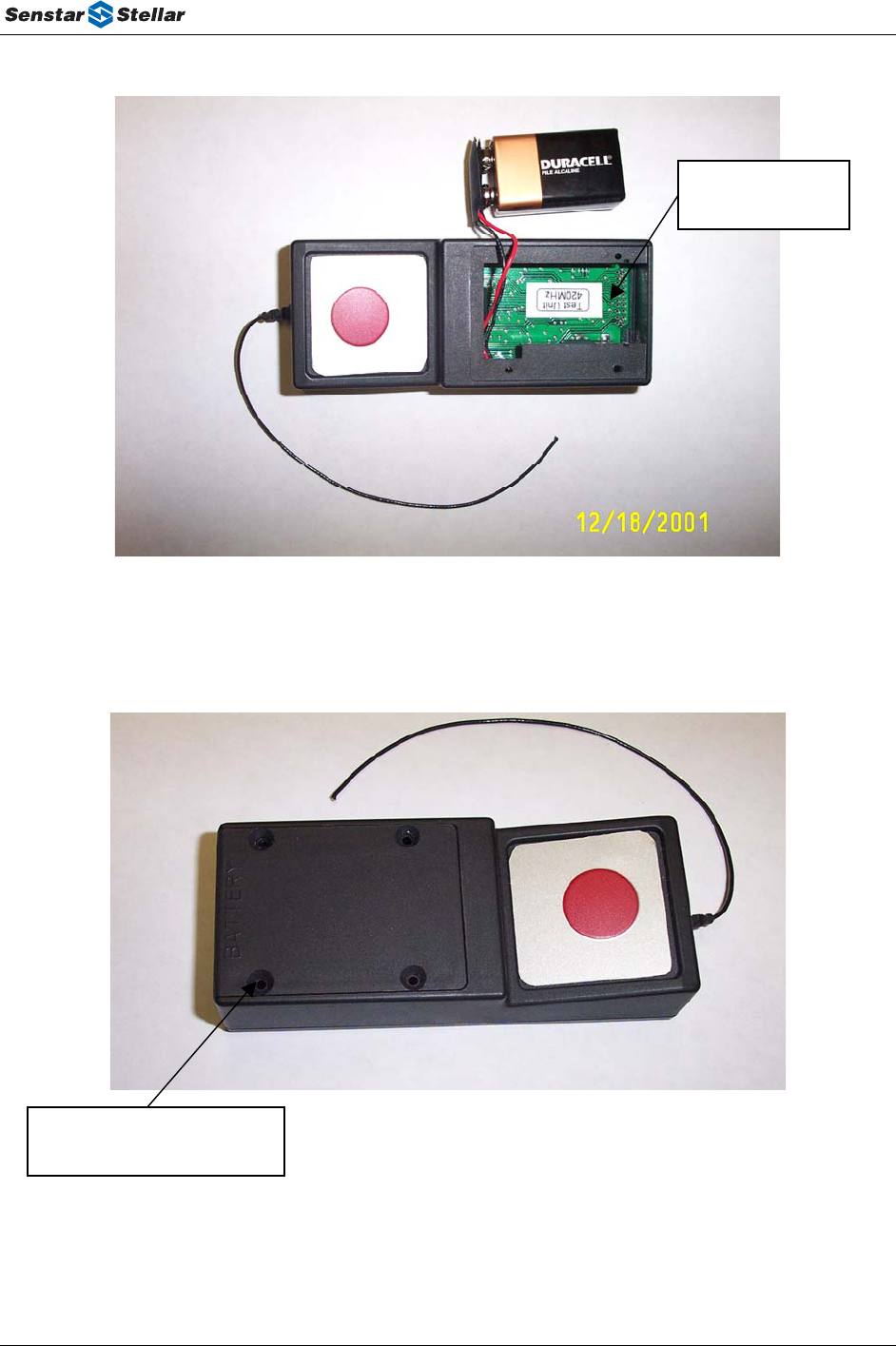
Battery Removal:
The battery is accessed by removing the battery cover (refer to Figures 3.2a and 3.2b below). Always
open the battery cover at a workstation equipped with electrostatic discharge (ESD) protection. Static
sensitive components are exposed when the battery cover is removed. Removal requires a TorxTM
security driver, Size T8 (McMaster Carr #7233A61). Remove the four screws.
Remove the battery from the battery compartment by gently tapping the transmitter case against the
palm of the hand while the battery cover is removed. The battery will fall into your hand, retained by
the flying leads of the battery clip. Carefully unsnap the battery clip and discard the old battery.
T1DA0502-001, Rev A Page 9

PPD Maintenance & Technical Manual
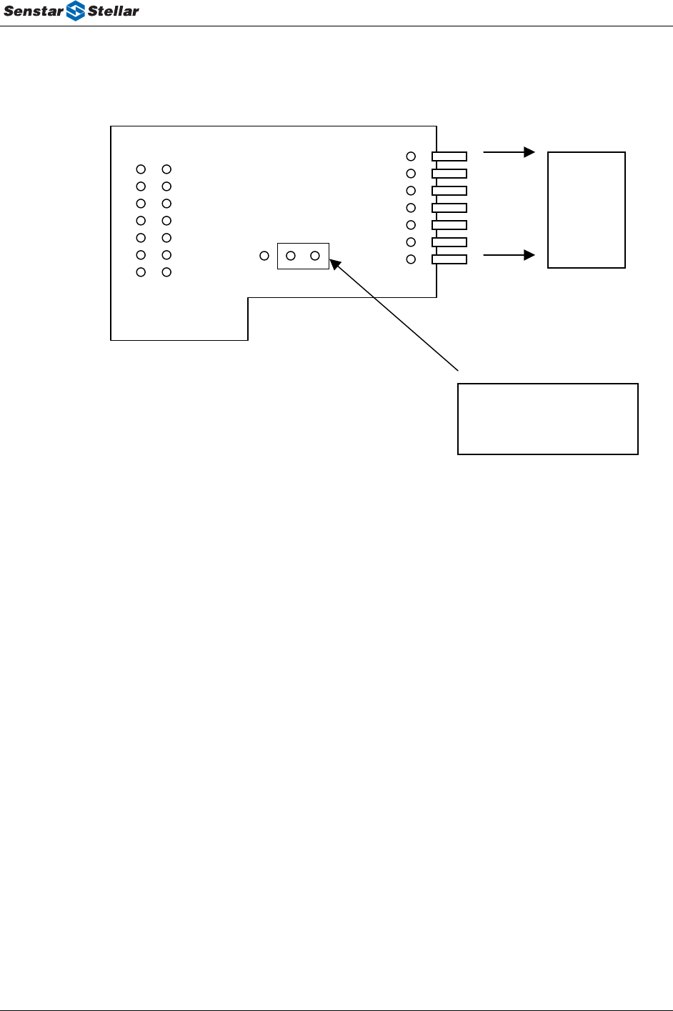
Replacement of Battery Following Low Battery Detection: Serial Numbers Less Than 5599
If the battery is being replaced due to low battery detection, the PPD must be reset before returning it
to operation. Before reconnecting the new battery, plug the PPD programming board into the
programming connector slot within the battery compartment. Make sure the programming board
jumper is in the position shown in Figure 3.2c. While the programming board is plugged in, plug in
the new battery to the battery clips (plug is polarized and will only snap on in one position). Remove
the programming board.
Place the battery into the battery compartment making sure the flying leads dress into the housing.
Replace the battery cover and four screws taking care not to over-tighten the self-tapping screws.
(Refer to PPD Programmer Manual for additional details concerning battery replacement and
programming).
Replacement of Battery Following Low Battery Detection: For Serial Numbers Greater Than 5600
Once the battery has been replaced, no additional programming is necessary to reset the 'low battery
detection'. This step is completed automatically.
Replacement of Battery before Low Battery Detection:
Anytime a new battery is installed in the unit, the Low Battery Reset procedure defined above must be
followed. The act of unplugging the battery will cause the PPDs low battery indicator to go true. This
is true even if a good battery is removed and then re-installed in the unit.
CAUTION
Replace only with the same or equivalent type battery recommended
by the manufacturer. Dispose of used batteries according to the
manufacturer's instructions.
T1DA0502-001, Rev A Page 10
PPD Maintenance & Technical Manual
Programming
Connector
Figure 3.2a
Battery Cover Screw location
(4 each)
Figure 3.2b
T1DA0502-001, Rev A Page 11
PPD Maintenance & Technical Manual
3 2 1
To Transmitter
Programming
Connecto
r
Position of Jumper to Reset
Low Battery Mode
Figure 3.2c
T1DA0502-001, Rev A Page 12
PPD Maintenance & Technical Manual
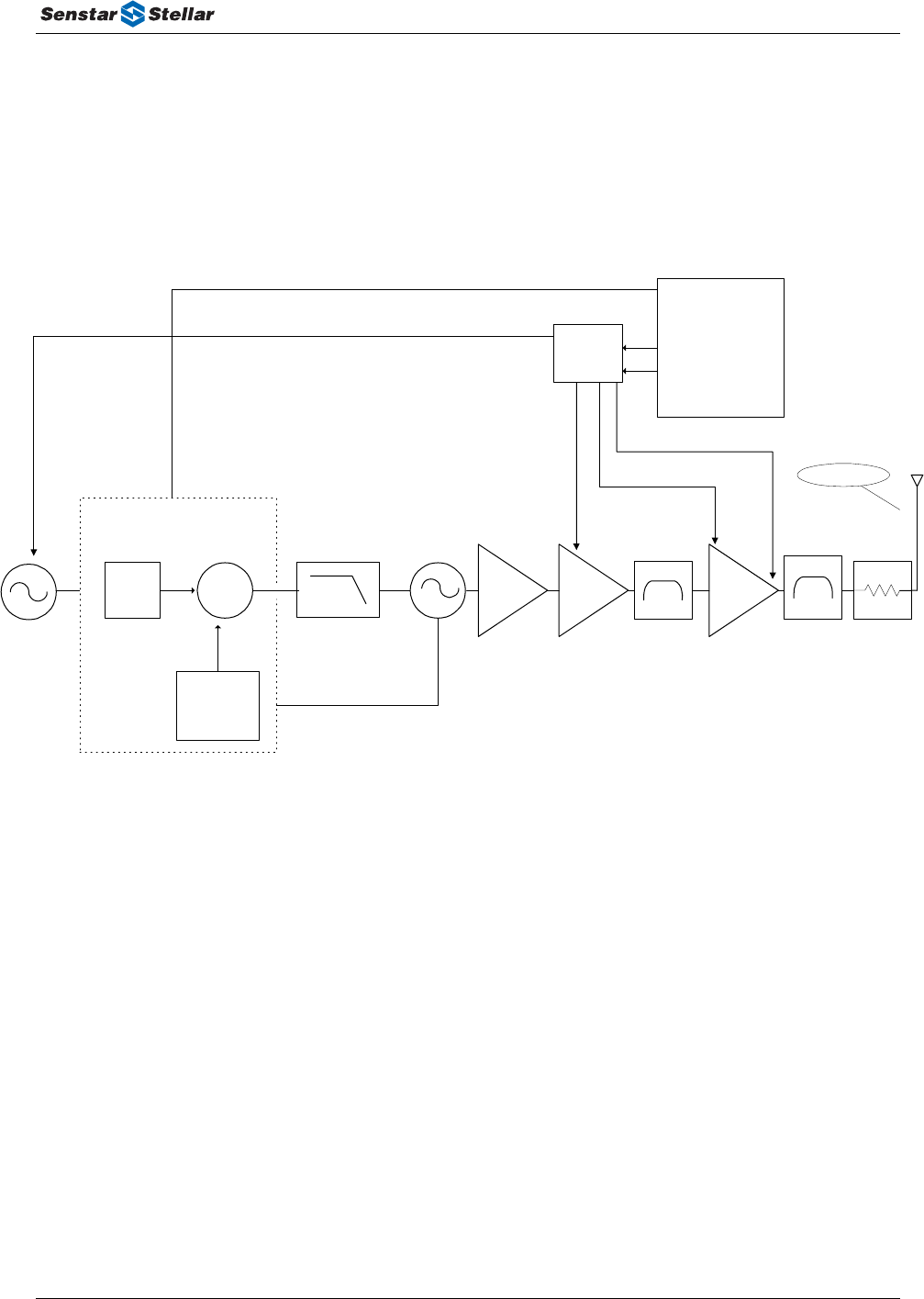
4.0 PPD THEORY OF OPERATION
The PPD unit’s electrical functional block diagram is illustrated below. This shows the unit elements
of the controller/digital and RF sections. For a more complete description of the unit elements, refer to
the sections below.
Driver
Stage
Reference
Oscillator
10 MHz
420-475 MHz
VCTCXO
Loop Filter
VCO
Buffer
Voltage Controlled
Oscillator
Final
PA
Atten
MRF917
NE85639
+17.0 dBm Max
Quad
D/A
Converter
Atmel uP
NE85639 NE85639
Filter
Final PA Pwr Adjust
Driver Pwr Adjust
TX Modulation and
Ref Osc Frequency Adjust
Antenna
Data, Clk, Strobe
Divide by
200
Fractional - N
Divide by
8400 - 9000
or
9000 - 9500
Reference
Frequency
50 kHz
SA8026A
Σ
Phase
Detector
Filter
Pin Diode Adjust
T1DA0502-001, Rev A Page 13

PPD Maintenance & Technical Manual
4.1 Transmitter Specifications
Model No: B76060
Supply Voltage 9 VDC (Duracell MN1604)
Current Drain: 110 mA when active, 16 microamperes
standby.
Temperature -40 Deg C to +60 Deg C
Operating Frequency Range 420-470 MHz
Channel Resolution 6.25 kHz
Output Power 17.0 dBm +/- 2 dB, measured into 50 Ohm
Load Impedance 50 Ohm
Modulation 2-FSK
Average Deviation 2.00 kHz +/-100Hz
Radiated Spurious Output per FCC Part 90, Industry Canada
Radiated Harmonic Output per FCC Part 90, Industry Canada
FCC ID: OQUB76060
Industry Canada ID: 3527195632
CSA Registration No: 163213
T1DA0502-001, Rev A Page 14
PPD Maintenance & Technical Manual
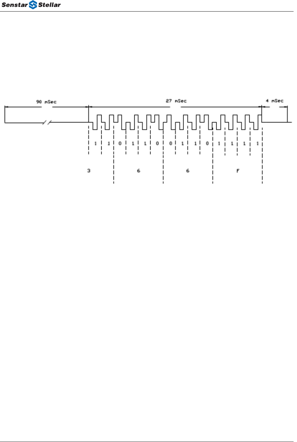
4.2 Digital Modulation
The digital modulation used in the Senstar-Stellar PPD unit is a tri-level 2-FSK format; i.e., the carrier
frequency is part of the modulated waveform. The base band waveform is redrawn below for a sample
ID word 366f (hex).
Transmitted data waveforms are generated by the microcontroller (Atmel AT90S2313) and fed to the
quad digital-to-analog converter (DAC - MAX533-pin 15). This DAC output waveform is fed to the
reference oscillator voltage controlled, input port (U3 - pin 1). The maximum voltage swing on the
reference oscillator is 0.5 V to 4.5 V (≈ +/- 10 ppm). This corresponds to a maximum possible
deviation swing at the transmitter output of 4.7 kHz peak.
The DAC has 8-bit resolution and deviation is controlled by setting the DAC output swing in the
factory. The VCTCXO is modulated with data and the transmitted deviation is measured with a
modulation analyzer at the antenna output. The test procedure requires the DAC peak-peak voltage
swing to be varied until the appropriate data average deviation level is recorded. This level is saved in
the microcontroller EEPROM and modulation limiting is provided via software setting of the DAC
maximum output voltage. Deviation is tested and confirmed in the factory test station prior to
shipment.
The transmitter was designed, using the appropriate data rate and deviation levels, to be
compliant with Part 90.217(b) of the FCC rules. Per 90.217(b), there is a spectral emissions
requirement and not a mask requirement. Hence, no data filtering is used.
T1DA0502-001, Rev A Page 15
PPD Maintenance & Technical Manual
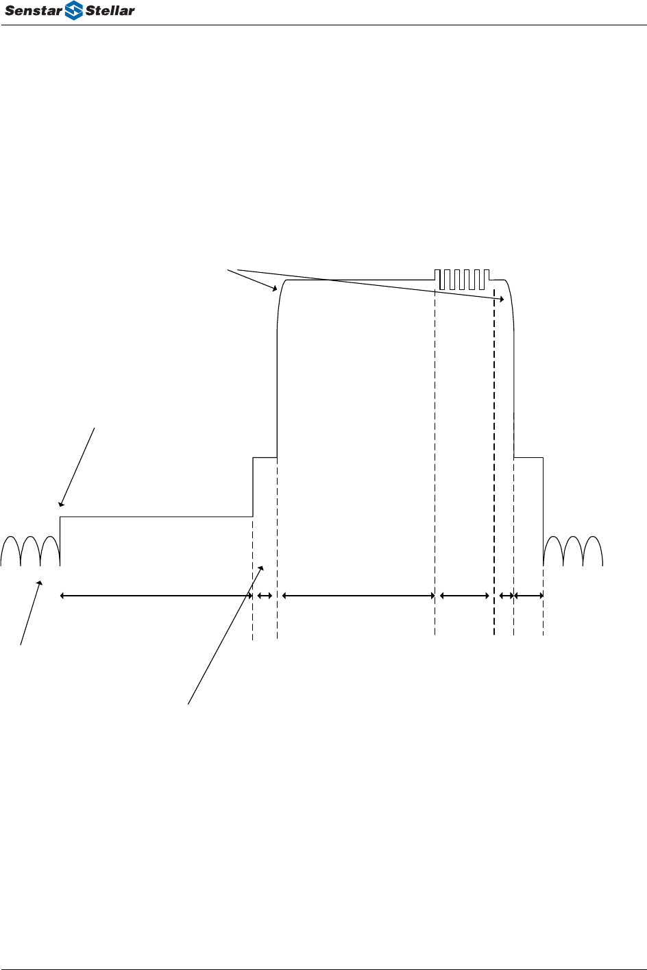
4.3 RF Output
This section details critical timing and power ramping waveforms. The waveform below
indicates the RF power levels versus time from the initial alarm activation to the end of the
transmission sequence.
< -60 dBc
< -45 dBc
0 dBc
-12 to -18 dBc
100 msec 5-10 msec 90 msec 27 msec
4-5 msec
Activation
TX Off (white noise)
TX Locked on Freq
Power ramping
-12 to -18 dBc
< -45 dBc
5-10 msec
T1DA0502-001, Rev A Page 16

PPD Maintenance & Technical Manual
4.4 PPD Detailed Hardware Description
The following describes design goals for each of the functional unit elements in the PPD. This section
provides typical performance characteristics of each unit element. These are not implied or guaranteed
requirements and are intended for reference purposes only.
4.4.1 Synthesizer
The PPD synthesizer covers the frequency range from 420 – 470 MHz in selectable channel
increments of 6.25 KHz. The customer specified operating frequency is factory set at time of
test/alignment. The unit elements of the synthesizer are described below.
Phase Lock Loop Integrated Circuit
The synthesizer IC used in the PPD unit is a Philips SA7026A. This is a dual fractional-N synthesizer
with a three-wire serial bus interface. For the PPD unit, only the main synthesizer is used. The
synthesizer is loaded with divider ratios and related data by the microcontroller on the three-wire bus.
6.25 kHz channelization is realized by programming the main and reference dividers to provide a 50
kHz phase detector comparison (reference) frequency and by operating the fractional-N accumulator
in a modulo-8 mode. A sampled output of the driver amplifier is fed back to the PLL IC (SA7026A)
to be divided down to the reference frequency of 50 kHz.
The SA7026A’s voltage supplies are divided into digital and analog. The digital supply runs directly
off the PPD’s regulated 3.3v. The analog/charge pump supply runs off the output of a +5V regulator
that is powered off a voltage “doubler” IC that boosts 3.3v up to approximately 6.6v. This technique
provides added tuning range for the VCO, allowing only two frequency splits. The approximate
current consumption of the synthesizer is 8 mA.
Loop Filter
This filter is comprised of a) a series RC to ground in shunt with the main charge pump of the
SA7026A (with the capacitor connected directly to the SA7026A’s speedup charge pump), b) a
smaller-value capacitor in shunt with the main charge pump, and c) a final series-R shunt-C low pass
section feeding the control port of the VCO.
Loop-response and modulation performance depend critically on specific component values, and
much effort was put into balancing various constraints on the loop filter. Two major constraints were
a) sufficient loop bandwidth so that the PLL would adequately track the 2-FSK-baseband-modulated
VCTCXO signal to impart system-acceptable fidelity in the modulated waveform, and b) sufficient
out-of-modulation-band rejection to suppress the synthesizer’s reference spurs to levels acceptable for
PPD operation and regulatory requirements.
T1DA0502-001, Rev A Page 17

PPD Maintenance & Technical Manual
4.4.2 Voltage Controlled Oscillator (VCO)
The VCO was implemented using a Motorola MRF917 BJT in a Colpitts oscillator configuration. The
design provides a tuning frequency range of 420 – 475 MHz. For interference and EMI reasons, the
VCO and VCO buffer circuits are enclosed in a shield that clips to the PCB.
The VCO varactor diode input is driven by the output of the PLL loop filter, setting the instantaneous
transmitter frequency. The varactor is capacitive coupled into the VCO’s L-C tank circuit.
4.4.3 VCO Buffer Amplifier
The VCO buffer amplifier was implemented using an NEC/CEL NE85639 bipolar RF transistor. The
VCO buffer amp provides isolation and gain for the VCO output. The buffer amp provides
approximately 13-15 dB of gain at its output.
The VCO buffer amplifier uses an RF-bypassed emitter-degeneration bias arrangement for good
temperature stability. The buffer’s input impedance is high so that loading effects on the VCO are
minimized.
4.4.4 Reference Oscillator (VCTCXO)
The reference oscillator is a 10MHz voltage-controlled temperature compensated crystal oscillator
(VCTXCO). It is manufactured by TEMEX, part number TTF 95V AAO 10.000. The voltage-
controlled input of the reference oscillator has two functions, 1) frequency adjust via the dc offset on
the voltage-controlled pin and 2) transmit modulation via an ac signal superimposed on the dc offset.
The VCTCXO voltage-control port is driven by the base band modulation waveform at an associated
dc-offset, thus driving both the PPD’s carrier frequency and deviation. Carrier frequency and average
deviation are set by measuring the PPD in Test Mode with a modulation analyzer, then adjusting the
base band modulation waveform’s mid, low, and high voltages. These values are saved in the
controller’s EEPROM.
The reference oscillator is a 5 volt nominal part, rather than 3.3 volts, and gets its supply voltage from
the same +5V regulator as the charge pump of the synthesizer. This was done to maximize the
voltage-tuning range of the VCTCXO function to encompass a) modulation, b) carrier frequency trim,
c) unit-unit variations, and d) crystal aging.
T1DA0502-001, Rev A Page 18

PPD Maintenance & Technical Manual
4.4.5 Driver Stage
The driver amplifier was implemented using a NEC/CEL NE85639. The driver amp has
approximately 9-11 dB of gain at its output.
The driver amplifier uses a software settable bias circuit. During the factory test, the microcontroller
will set the bias level of the driver amplifier by varying the quad DAC output voltage accordingly
(MAX 533-pin 2) while measuring the bias current and/or output power. This bias set point effectively
sets the current and gain of the driver amplifier stage.
To minimize gain variation over temperature, the driver amplifier implements a thermistor (RT1) in
its bias circuit. The negative temperature coefficient, thermistor’s resistance varies inversely with
temperature to adjust the bias current in the device. This keeps gain constant over the environmental
conditions defined for the PPD.
4.4.6 Band Pass Interstage Filter
The driver amplifier feeds the final power amplifier stage through a simple band pass filter consisting
of a parallel inductor-capacitor in shunt with the driver amplifier’s output. This provides spurious and
out-of-band rejection prior to final stage amplification.
4.4.7 Final Amplifier
The final amplifier was implemented using a NEC/CEL NE85639 bipolar RF transistor. The final
amp has approximately 9-11 dB of gain at its output.
T1DA0502-001, Rev A Page 19

PPD Maintenance & Technical Manual
T1DA0502-001, Rev A Page 20