Senstar LM100 outdoor perimeter intrusion detection and lighting system User Manual Senstar LM100 Product Guide
Senstar Corporation outdoor perimeter intrusion detection and lighting system Senstar LM100 Product Guide
Senstar >
user manual

Product
Guide
Senstar LM100™
Intelligent Perimeter Lighting and Sensing Solution
E8DA0102-001 Rev A
December 11, 2017

Page 2 Senstar LM100 Product Guide
Senstar Corporation
Website: www.senstar.com
Email address: info@senstar.com
E8DA0102-001 Rev A
December 11, 2017
Senstar and the Senstar logo are registered trademarks, and Silver Network is a trademark of Senstar Corporation. Product
names and Company names included in this document are used only for identification purposes and are the property of, and
may be trademarks of, their respective owners. Copyright © 2017, Senstar Corporation, all rights reserved. Printed in Canada.
The information provided in this guide has been prepared by Senstar Corporation to the best of its ability. Senstar Corporation is
not responsible for any damage or accidents that may occur due to errors or omissions in this guide. Senstar Corporation is not
liable for any damages, or incidental consequences, arising from the use of, or the inability to use, the software and equipment
described in this guide. Senstar Corporation is not responsible for any damage or accidents that may occur due to information
about items of equipment or components manufactured by other companies. Features and specifications are subject to change
without notice.
Any changes or modifications to the software or equipment that are not expressly approved by Senstar Corporation void the
manufacturer’s warranty, and could void the user’s authority to operate the equipment.
The figures included in this document are for illustration purposes only, and may differ from the actual equipment.
Compliance:
This equipment should be installed and operated such that the transmit antenna is 25 mm (1 in.) or more away from any person
during the device’s operation.
Canada: Innovation, Science and Economic Development Canada Certification Number:
1454B-LM100 (Senstar LM100 luminaire)
CAN ICES-3B/NMB-3B
This device complies with Innovation, Science and Economic Development Canada license-exempt RSS standard(s).
Operation is subject to the following two conditions: (1) This device may not cause harmful interference, and (2) this device must
accept any interference received, including interference that may cause undesired operation.
Ce dispositif est conforme aux normes CNR Innovation, Sciences et Développement économique Canada applicables aux
appareils radio exempts de licence. Son fonctionnement est sujet aux deux conditions suivantes : 1) le dispositif ne doit pas
produire de brouillage préjudiciable; et 2) il doit accepter tout brouillage reçu, y compris un brouillage susceptible de provoquer
un fonctionnement indésirable.
USA: FCC Identification Number: I5TLM100 (Senstar LM100 luminaire)
Changes or modifications not expressly approved by Senstar Corporation could void the user's authority to operate the
equipment.
FCC Certification - This device complies with part 15 of the FCC Rules. Operation is subject to the following two conditions: (1)
This device may not cause harmful interference, and (2) this device must accept any interference received, including
interference that may cause undesired operation.
This equipment has been tested and found to comply with the limits for a Class B digital device, pursuant to Part 15 of the FCC
Rules. These limits are designed to provide reasonable protection against harmful interference in a residential installation. This
equipment generates, uses and can radiate radio frequency energy and, if not installed and used in accordance with the
instructions, may cause harmful interference to radio communications. However, there is no guarantee that interference will not
occur in a particular installation. If this equipment does cause harmful interference to radio or television reception, which can be
determined by turning the equipment off and on, the user is encouraged to try to correct the interference by one or more of the
following measures:
Reorient or relocate the receiving antenna.
Increase the separation between the equipment and receiver.
Connect the equipment into an outlet on a circuit different from that to which the receiver is connected.
Consult the dealer or an experienced radio/TV technician for help.
Europe:
This device complies with ETSI standard EN 300 440 for European operation.
The use of shielded cables is required for compliance.
Senstar Corporation’s Quality Management System is ISO 9001:2008 registered.

Senstar LM100 Product Guide Page 3
Table of Contents
1 System planning - - - - - - - - - - - - - - - - - - - - - - - - - - - - - - - - - - - - - - - - - -7
Description - - - - - - - - - - - - - - - - - - - - - - - - - - - - - - - - - - - - - - - - - - - - - - - - - - - - 7
Senstar LM100 luminaires - - - - - - - - - - - - - - - - - - - - - - - - - - - - - - - - - - - - - - - - - - - - 9
Senstar LM100 luminaire AP - - - - - - - - - - - - - - - - - - - - - - - - - - - - - - - - - - - - - - - - - - - - - 10
Senstar LM100 gateway - - - - - - - - - - - - - - - - - - - - - - - - - - - - - - - - - - - - - - - - - - - - 10
The Universal Configuration Module - - - - - - - - - - - - - - - - - - - - - - - - - - - - - - - - - - - 11
Alarm communication options - - - - - - - - - - - - - - - - - - - - - - - - - - - - - - - - - - - - - - - - 11
Relay Output Card - - - - - - - - - - - - - - - - - - - - - - - - - - - - - - - - - - - - - - - - - - - - - - - - - - - - 11
Dry Contact Input Card - - - - - - - - - - - - - - - - - - - - - - - - - - - - - - - - - - - - - - - - - - - - - - - - - 11
Fail-safe relay operation - - - - - - - - - - - - - - - - - - - - - - - - - - - - - - - - - - - - - - - - - - - - - - - - 11
Power source and wiring - - - - - - - - - - - - - - - - - - - - - - - - - - - - - - - - - - - - - - - - - - - - 12
Auxiliary device output power - - - - - - - - - - - - - - - - - - - - - - - - - - - - - - - - - - - - - - - - - - - - - 12
Power over Ethernet - - - - - - - - - - - - - - - - - - - - - - - - - - - - - - - - - - - - - - - - - - - - - - - - - - - 12
Grounding considerations - - - - - - - - - - - - - - - - - - - - - - - - - - - - - - - - - - - - - - - - - - - - - - - 13
Alarm monitoring - - - - - - - - - - - - - - - - - - - - - - - - - - - - - - - - - - - - - - - - - - - - - - - - - 13
NM Mode alarm reporting - - - - - - - - - - - - - - - - - - - - - - - - - - - - - - - - - - - - - - - - - - - - - - - 13
Security factors - - - - - - - - - - - - - - - - - - - - - - - - - - - - - - - - - - - - - - - - - - - - - - - - 13
Fence structures - - - - - - - - - - - - - - - - - - - - - - - - - - - - - - - - - - - - - - - - - - - - - - - 14
Standard flexible fence types - - - - - - - - - - - - - - - - - - - - - - - - - - - - - - - - - - - - - - - - - 14
Chain-link fence - - - - - - - - - - - - - - - - - - - - - - - - - - - - - - - - - - - - - - - - - - - - - - - - - - - - - - 14
Welded-mesh fences - - - - - - - - - - - - - - - - - - - - - - - - - - - - - - - - - - - - - - - - - - - - - - - - - - - 14
Expanded metal fences - - - - - - - - - - - - - - - - - - - - - - - - - - - - - - - - - - - - - - - - - - - - - - - - - 15
Rigid fence types - - - - - - - - - - - - - - - - - - - - - - - - - - - - - - - - - - - - - - - - - - - - - - - - - 15
Palisade fences - - - - - - - - - - - - - - - - - - - - - - - - - - - - - - - - - - - - - - - - - - - - - - - - - - - - - - 15
Climb-over deterrent hardware - - - - - - - - - - - - - - - - - - - - - - - - - - - - - - - - - - - - - - - 15
Barbed wire - - - - - - - - - - - - - - - - - - - - - - - - - - - - - - - - - - - - - - - - - - - - - - - - - - - - - - - - - 16
Razor ribbon - - - - - - - - - - - - - - - - - - - - - - - - - - - - - - - - - - - - - - - - - - - - - - - - - - - - - - - - - 16
Gates - - - - - - - - - - - - - - - - - - - - - - - - - - - - - - - - - - - - - - - - - - - - - - - - - - - - - - - - - 16
Environment - - - - - - - - - - - - - - - - - - - - - - - - - - - - - - - - - - - - - - - - - - - - - - - - - - - - 17
Site Survey - - - - - - - - - - - - - - - - - - - - - - - - - - - - - - - - - - - - - - - - - - - - - - - - - - - 17
Equipment layout - - - - - - - - - - - - - - - - - - - - - - - - - - - - - - - - - - - - - - - - - - - - - - 17
Installation overview - - - - - - - - - - - - - - - - - - - - - - - - - - - - - - - - - - - - - - - - - - - - - - - 18
2 Installation - - - - - - - - - - - - - - - - - - - - - - - - - - - - - - - - - - - - - - - - - - - - - 19
Installing LM100 luminaires - - - - - - - - - - - - - - - - - - - - - - - - - - - - - - - - - - - - - - - 19
At regular fence posts - - - - - - - - - - - - - - - - - - - - - - - - - - - - - - - - - - - - - - - - - - - - - - - - - - 19

Page 4 Senstar LM100 Product Guide
Tools and equipment - - - - - - - - - - - - - - - - - - - - - - - - - - - - - - - - - - - - - - - - - - - - - - - - - - 19
At corners or heavy gauge posts - - - - - - - - - - - - - - - - - - - - - - - - - - - - - - - - - - - - - - - - - - 22
Installing luminaires on welded-mesh fence - - - - - - - - - - - - - - - - - - - - - - - - - - - - - - - - - - 22
Installing luminaires on rigid fences - - - - - - - - - - - - - - - - - - - - - - - - - - - - - - - - - - - - - - - - 23
Surface mounting luminaires - - - - - - - - - - - - - - - - - - - - - - - - - - - - - - - - - - - - - - - - - - - - - 24
Power cable installation - - - - - - - - - - - - - - - - - - - - - - - - - - - - - - - - - - - - - - - - - - - - -24
Tools and equipment - - - - - - - - - - - - - - - - - - - - - - - - - - - - - - - - - - - - - - - - - - - - - - - - - - 25
Installing the luminaire AP - - - - - - - - - - - - - - - - - - - - - - - - - - - - - - - - - - - - - - - - - - - -27
Installing the LM100 gateway - - - - - - - - - - - - - - - - - - - - - - - - - - - - - - - - - - - - - -27
Cable entry ports - - - - - - - - - - - - - - - - - - - - - - - - - - - - - - - - - - - - - - - - - - - - - - - - - - - - - 29
Free-standing or fence post mounting the enclosure - - - - - - - - - - - - - - - - - - - - - - - - - - - - 29
Surface mounting - - - - - - - - - - - - - - - - - - - - - - - - - - - - - - - - - - - - - - - - - - - - - - - - - - - - - 31
Grounding - - - - - - - - - - - - - - - - - - - - - - - - - - - - - - - - - - - - - - - - - - - - - - - - - - - - - - -32
I/O ports - - - - - - - - - - - - - - - - - - - - - - - - - - - - - - - - - - - - - - - - - - - - - - - - - - - - - - - -32
I/O port jumpers - - - - - - - - - - - - - - - - - - - - - - - - - - - - - - - - - - - - - - - - - - - - - - - - - - - - - - 32
Outputs - - - - - - - - - - - - - - - - - - - - - - - - - - - - - - - - - - - - - - - - - - - - - - - - - - - - - - - - - - - - 32
Relay contact ratings - - - - - - - - - - - - - - - - - - - - - - - - - - - - - - - - - - - - - - - - - - - - - - - - - - 33
Auxiliary inputs - - - - - - - - - - - - - - - - - - - - - - - - - - - - - - - - - - - - - - - - - - - - - - - - - - - - - - 33
Gateway wiring connections - - - - - - - - - - - - - - - - - - - - - - - - - - - - - - - - - - - - - - - - - -34
Silver Network wiring connections - - - - - - - - - - - - - - - - - - - - - - - - - - - - - - - - - - - - - -36
Silver Network specifications - - - - - - - - - - - - - - - - - - - - - - - - - - - - - - - - - - - - - - - - - - - - - 36
Silver Network data path connections - - - - - - - - - - - - - - - - - - - - - - - - - - - - - - - - - - -38
Power supply connections - - - - - - - - - - - - - - - - - - - - - - - - - - - - - - - - - - - - - - - - - - -40
Network power supply - - - - - - - - - - - - - - - - - - - - - - - - - - - - - - - - - - - - - - - - - - - - - - - - - 40
Local power supply - - - - - - - - - - - - - - - - - - - - - - - - - - - - - - - - - - - - - - - - - - - - - - - - - - - - 40
Power over Ethernet - - - - - - - - - - - - - - - - - - - - - - - - - - - - - - - - - - - - - - - - - - - - - - - - - - - 40
Backup power - - - - - - - - - - - - - - - - - - - - - - - - - - - - - - - - - - - - - - - - - - - - - - - - - - - - - - - 40
Using the wireless gate sensor - - - - - - - - - - - - - - - - - - - - - - - - - - - - - - - - - - - - -41
3 Calibration & setup - - - - - - - - - - - - - - - - - - - - - - - - - - - - - - - - - - - - - - - 43
The Universal Configuration Module - - - - - - - - - - - - - - - - - - - - - - - - - - - - - - - - -43
Senstar LM100 configuration overview - - - - - - - - - - - - - - - - - - - - - - - - - - - - - - -47
Senstar LM100 definitions - - - - - - - - - - - - - - - - - - - - - - - - - - - - - - - - - - - - - - - - - - - -47
Senstar LM100 alarm detection - - - - - - - - - - - - - - - - - - - - - - - - - - - - - - - - - - - - - - - -48
Intrusion detection - - - - - - - - - - - - - - - - - - - - - - - - - - - - - - - - - - - - - - - - - - - - - - - - -49
Cut detection - - - - - - - - - - - - - - - - - - - - - - - - - - - - - - - - - - - - - - - - - - - - - - - - - - - - - - - - 49
Climb detection - - - - - - - - - - - - - - - - - - - - - - - - - - - - - - - - - - - - - - - - - - - - - - - - - - - - - - 49
Initial gateway setup - - - - - - - - - - - - - - - - - - - - - - - - - - - - - - - - - - - - - - - - - - - -49
Connecting the UCM via USB - - - - - - - - - - - - - - - - - - - - - - - - - - - - - - - - - - - - - - - - -50
Setting the gateway’s Silver Network address - - - - - - - - - - - - - - - - - - - - - - - - - - - - - -50
Silver Network configuration - - - - - - - - - - - - - - - - - - - - - - - - - - - - - - - - - - - - - - - - - -50
Sequencing the heads - - - - - - - - - - - - - - - - - - - - - - - - - - - - - - - - - - - - - - - - - - -50
Compiling the Unordered Heads list - - - - - - - - - - - - - - - - - - - - - - - - - - - - - - - - - - - - - - - - 52
Compiling the Ordered Heads list - - - - - - - - - - - - - - - - - - - - - - - - - - - - - - - - - - - - - - - - - 52
Compiling the Head Sequence list - - - - - - - - - - - - - - - - - - - - - - - - - - - - - - - - - - - - - - - - - 53
Senstar LM100 calibration - - - - - - - - - - - - - - - - - - - - - - - - - - - - - - - - - - - - - - - -54
The Sensitivity Profile - - - - - - - - - - - - - - - - - - - - - - - - - - - - - - - - - - - - - - - - - - - - - - -54
Recording the Sensitivity Profile - - - - - - - - - - - - - - - - - - - - - - - - - - - - - - - - - - - - - - - - - - 54
Detection parameter setup - - - - - - - - - - - - - - - - - - - - - - - - - - - - - - - - - - - - - - - - - - -55
Defining the luminaire segments and alarm zones - - - - - - - - - - - - - - - - - - - - - - - - - - -56
Defining the initial zone - - - - - - - - - - - - - - - - - - - - - - - - - - - - - - - - - - - - - - - - - - - - - - - - - 57

Senstar LM100 Product Guide Page 5
Defining the segments - - - - - - - - - - - - - - - - - - - - - - - - - - - - - - - - - - - - - - - - - - - - - - - - - - 57
Verifying the luminaire segment boundaries - - - - - - - - - - - - - - - - - - - - - - - - - - - - - - - - - - 58
Setting the Threshold - - - - - - - - - - - - - - - - - - - - - - - - - - - - - - - - - - - - - - - - - - - - - - 58
Segment threshold setting procedure - - - - - - - - - - - - - - - - - - - - - - - - - - - - - - - - - - - - - - 59
Intrusion simulations - - - - - - - - - - - - - - - - - - - - - - - - - - - - - - - - - - - - - - - - - - - - - - - 60
Scheduling routine light activation - - - - - - - - - - - - - - - - - - - - - - - - - - - - - - - - - - - 61
Scheduling routine luminaire activation - - - - - - - - - - - - - - - - - - - - - - - - - - - - - - - - - - - - - - 61
Input/output configuration - - - - - - - - - - - - - - - - - - - - - - - - - - - - - - - - - - - - - - - - 62
Specifying the Auxiliary I/O control mode, I/O type and option card - - - - - - - - - - - - - - 62
Auxiliary (Aux) inputs - - - - - - - - - - - - - - - - - - - - - - - - - - - - - - - - - - - - - - - - - - - - - - 62
Local control mode - - - - - - - - - - - - - - - - - - - - - - - - - - - - - - - - - - - - - - - - - - - - - - - - - - - - 62
Remote control mode - - - - - - - - - - - - - - - - - - - - - - - - - - - - - - - - - - - - - - - - - - - - - - - - - - 62
Remote light activation - - - - - - - - - - - - - - - - - - - - - - - - - - - - - - - - - - - - - - - - - - - - - - - - - 63
Input wiring configurations - - - - - - - - - - - - - - - - - - - - - - - - - - - - - - - - - - - - - - - - - - - - - - - 63
Input configuration procedure - - - - - - - - - - - - - - - - - - - - - - - - - - - - - - - - - - - - - - - - - - - - - 64
Output relays - - - - - - - - - - - - - - - - - - - - - - - - - - - - - - - - - - - - - - - - - - - - - - - - - - - 64
Output relay setup (Local control mode) - - - - - - - - - - - - - - - - - - - - - - - - - - - - - - - - - - - - - 64
Output relay setup (Remote control mode) - - - - - - - - - - - - - - - - - - - - - - - - - - - - - - - - - - - 64
Linking segments to relays (local control mode) - - - - - - - - - - - - - - - - - - - - - - - - - - - 65
System test procedure - - - - - - - - - - - - - - - - - - - - - - - - - - - - - - - - - - - - - - - - - - - 65
4 Maintenance - - - - - - - - - - - - - - - - - - - - - - - - - - - - - - - - - - - - - - - - - - - - 67
Recommended maintenance - - - - - - - - - - - - - - - - - - - - - - - - - - - - - - - - - - - - - - 67
Preventing weather related nuisance alarms - - - - - - - - - - - - - - - - - - - - - - - - - - - - - - - - - - 68
Adjusting the Target Filters - - - - - - - - - - - - - - - - - - - - - - - - - - - - - - - - - - - - - - - - - - - - - - 68
Replacing the gateway - - - - - - - - - - - - - - - - - - - - - - - - - - - - - - - - - - - - - - - - - - 69
Removing the gateway assembly - - - - - - - - - - - - - - - - - - - - - - - - - - - - - - - - - - - - - - - - - - 69
Replacing the gateway assembly - - - - - - - - - - - - - - - - - - - - - - - - - - - - - - - - - - - - - - - - - - 69
Updating the Senstar LM100 Firmware - - - - - - - - - - - - - - - - - - - - - - - - - - - - - - - 69
a Parts list - - - - - - - - - - - - - - - - - - - - - - - - - - - - - - - - - - - - - - - - - - - - - - - 71
b Specifications - - - - - - - - - - - - - - - - - - - - - - - - - - - - - - - - - - - - - - - - - - - 73

Page 6 Senstar LM100 Product Guide
Related publications:
The following documents, included on the Senstar LM100 CD, contain information that may be
applicable to the Senstar LM100 system
•E8DA0103-001 Senstar LM100 quickstart instruction
•00DA0803-001 Installing the network interface card
•00DA1003-002 UltraLink I/O
•00DA1203-001 Installing the network interface unit
•00DA1503-001 Installing I/O cards
•00DA0109-001 Network Manager overview
•E7DA0103-001 Wireless Gate Sensor
Senstar LM100 Product Guide Page 7
1 System planning
Description
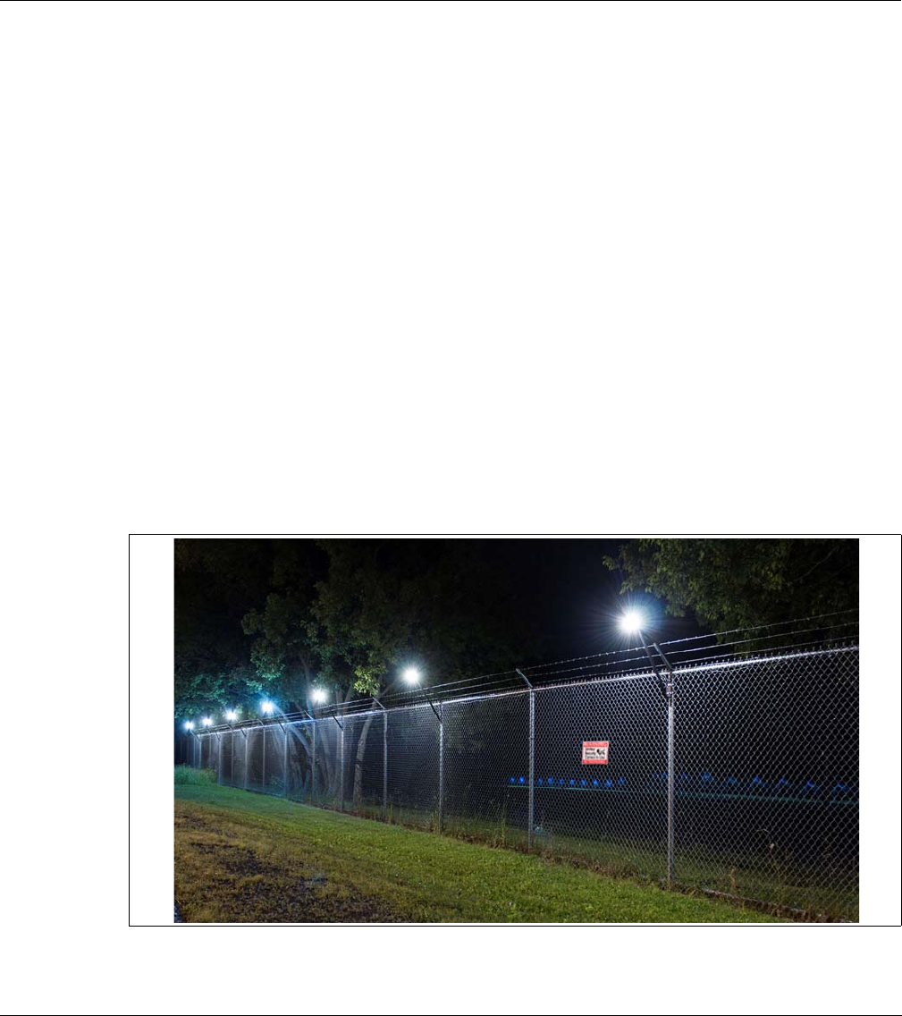
The Senstar LM100 intelligent perimeter lighting and sensing solution combines high-intensity
LED lighting with an accelerometer-based vibration detection sensor. The system is comprised of
a distributed set of LM100 luminaires, which include the LED lights and the vibration detecting
sensor, a gateway device that processes the signals from the luminaires, and a luminaire AP
(access point) that provides an RS-485 half-duplex connection between the RF-based luminaires
and the gateway.
The Senstar LM100 luminaires are typically mounted on the perimeter fence, but can also be
mounted on walls or other surfaces. The luminaires communicate over a proprietary wireless
mesh network transmitting status information and receiving control point commands from the
gateway via the hard-wired connection to the luminaire AP. The gateway provides the user
interface to the distributed luminaires as well as the interface between the luminaires and a
security management system (SMS). The gateway device supports up to 100 luminaires (the
luminaire AP is included in the 100 unit limit for each Senstar LM100 system).
Figure 1: luminaires at night

Description
Page 8 Senstar LM100 Product Guide
For optimum performance and the highest probability of detection (Pd) the Senstar LM100
luminaires can be mounted on fences up to 3.6 m (12 ft.) high, with up to 6 m (20 ft.) separation
between luminaires. With 6 m spacing between luminaires, one Senstar LM100 system can
protect up to 600 m (1970 ft.) of perimeter fencing. The luminaires can be mounted at various
heights on the fence posts to avoid contact with barbed wire outriggers at the top of the fence.
The Senstar LM100 system can be configured to protect most types of fences with user-
configurable detection parameters and light activation controls. Each system supports up to 50
distinct alarm zones and each alarm zone can include from 1 to 100 luminaires. In addition to
alarm detection and response, each software defined zone can follow a preset schedule for
routine light activation. The luminaire detection parameters and alarm response are configured
through the LM100 gateway. The lights can be turned ON, OFF, and Strobed in response to an
alarm, individually or grouped by zone. The luminaires can also have their brightness adjusted for
both routine lighting and alarm response.
The LEDs on the Senstar LM100 luminaires are optimized to provide full spectrum lighting, to
ensure high quality images for CCTV coverage. The LEDs provide uniform directional lighting
along the fence line with an elliptical 120º coverage pattern that minimizes light pollution. The LED
lights are fully ON or OFF instantly, without a warm-up period and each luminaire consumes only
2.5 W. The Senstar LM100 system is so energy efficient that a complete system with 100
luminaires consumes about the same amount of power as a single high pressure sodium light.
The Senstar LM100 gateway includes ten I/O ports that are individually selectable as inputs or
outputs with normally open or normally closed contacts. An I/O option card can be added to the
gateway to provide an additional 4 inputs or 4 outputs. The I/O points can be controlled locally by
the gateway with the outputs used to signal alarm and supervision conditions, and the inputs used
to activate luminaire zones. Alternately, the I/O points can be controlled remotely by a security
management system (SMS). In this case the outputs are used to activate auxiliary equipment and
the inputs are used to communicate the status of auxiliary devices to the SMS. The outputs are
individually configurable and can source up to 100 mA to power auxiliary equipment. The inputs to
the gateway must be voltage free. The Senstar LM100 supports the Wireless Gate Sensor (WGS)
to provide coverage for up to 4 gates per system. The WGS requires a receiver module which
mounts on the gateway circuit card assembly (CCA) and at least one gate sensor for each
protected gate.
The Senstar LM100 system can operate as a standalone system which reports alarm conditions
via contact closure outputs. Each luminaire can be configured to respond to alarm conditions and
to automatically turn ON and OFF according to a user-defined schedule, and to activate other
equipment (via gateway outputs). Each luminaire can also be configured to respond to dry contact
inputs from other equipment such as a photo cell for routine light activation.
The Senstar LM100 can be part of a Silver Network based security system. In this case the
gateway requires a Network Interface Card that connects to a PC running Senstar’s Network
Manager (NM) service. The NM interfaces between the Senstar LM100 and a security
management system such as StarNet 2 or the Alarm Integration Module. The Senstar LM100 can
easily be integrated into any SMS that accepts contact closure inputs. There are 16 channels
available to prevent interference between closely located Senstar LM100 systems (400 m
separation is required between Senstar LM100 systems operating on the same channel).
Note It may be possible for the Senstar LM100 to protect fences higher than
3.6 m by installing the luminaires at the 3.6 m (12 ft.) point on the fence
posts; or by using the minimum separation between luminaires of 3 m.
However, Senstar strongly recommends a trial installation and testing
the installation thoroughly to ensure the detection sensitivity meets the
site requirements.
Description
Senstar LM100 Product Guide Page 9
Senstar LM100 luminaires
The luminaire is both the sensing unit and the lighting unit for the Senstar LM100 system. The
luminaires communicate over a wireless mesh network, relaying status information to the gateway
via the luminaire AP. Luminaires are usually mounted near the tops of the fence posts, and can
also be mounted on walls or other flat surfaces. The luminaire head contains the electronic
components (a MEMs sensor, LED lights and a wireless RF transceiver). Each Senstar LM100
gateway supports up to 100 luminaires (1 luminaire AP + 99 luminaires). The luminaires are
configured remotely through a UCM connection to the gateway. One or more luminaires can be
grouped into segments, and the segments can be grouped into zones (via the UCM software). The
detection parameters are set globally for all luminaires. However, each luminaire segment has an
independent alarm threshold and each luminaire zone can have independent light activation
controls. The global detection parameters include an Event Window, an Event Count and an Alarm
Window. There is also a Target Filter which can be used to screen out some sources of
environmental and mechanical noise. Each luminaire is supervised to protect against tampering
and the removal of the device.
The luminaire’s lighting properties are also set globally. This includes brightness, and response to
alarm conditions. There are 5 selectable luminaire alarm responses. Luminaires can be turned
ON, OFF, or strobed individually or in zones. For example, the luminaire that detects an intrusion
attempt can be strobed and the zone it is assigned to can be turned ON. It is also possible to
configure a luminaire zone to follow a routine lighting schedule, with or without providing intrusion
detection. For example, a number of luminaires could be used to provide walkway lighting and
building entrance lighting. These luminaires would be scheduled to turn on at dusk and off at
dawn. Alarm detection is not desired for these luminaires so the detection for this group of
luminaires would be disabled.
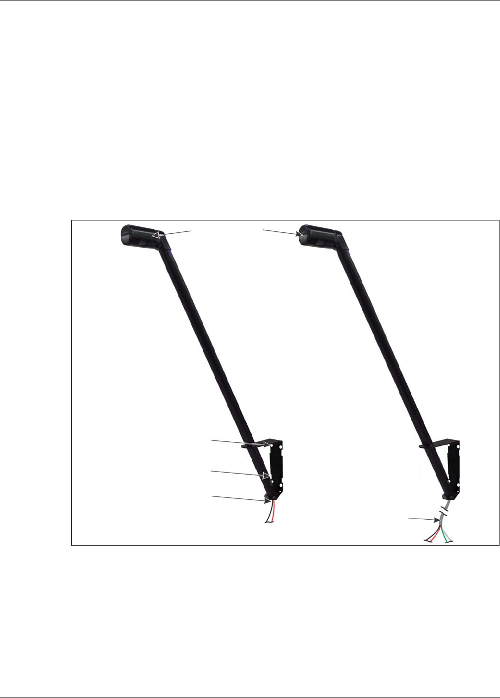
Figure 2: Senstar 100LM luminaire and luminaire AP
luminaire head
6 mm (¼ in.) holes for wall-mounting
clamp slots for post-mounting
2-conductor power cable connection
LED lights and electronics
RS-485 (green A white B)
luminaire AP with power
luminaire AP
luminaire
(red + black -)
power cable (red + black -)
and shielded data connection

Description
Page 10 Senstar LM100 Product Guide
Senstar LM100 luminaire AP
The luminaire AP functions as a standard luminaire providing intrusion detection and routine
lighting. It also serves as the access point through which the distributed luminaires communicate
with the gateway device. A two-wire RS-485 connection between the AP and the gateway enables
half-duplex communication between the two devices. Individual luminaires are polled for status
information, and when an alarm condition occurs, the luminaire detecting the alarm transmits the
status change. This information is passed over the wireless mesh network until it is received by the
luminaire AP. The luminaire AP sends the data to the gateway over the RS-485 connection. The
gateway processes the received signals and triggers an alarm when the information indicates a
valid alarm. The luminaire AP includes a 3 m (10 ft.) 4-conductor cable to make the power and
data connection to the gateway. The luminaire AP can be installed up to 100 m (328 ft.) away from
the gateway by splicing in a suitable length of data/power cable. To use the extended cable length
requires a minimum 24 VDC power supply.
Senstar LM100 gateway
The gateway is the central controller for the Senstar LM100 system. It communicates with the
distributed luminaires through a 2-wire RS-485 connection to the luminaire AP. The gateway
receives the alarm and status information from the luminaires, and depending on the method of
alarm reporting, it either passes the data to the Silver Network Manager (NM) or it activates the
onboard outputs to signal alarm conditions and status information. System setup and configuration
for the luminaires is done using the Universal Configuration Module (UCM) through either a direct
USB connection to the gateway device, or remotely through the Silver Network Manager.
The gateway can be mounted outdoors on a post, either on, or separate from, the fence on which
the luminaires are installed. A rigid fixed post is recommended for outdoor applications. The
gateway can also be installed indoors or outdoors on a flat stable surface. Post-mounting
hardware is supplied for post sizes ranging from 4.5 cm to 12.7 cm (1¾ in. to 5 in.). The hardware
required for surface-mounting the gateway is customer-supplied. The gateway enclosure is hinged
on one side and includes a lockable latch (padlock not included).
The gateway includes ten input/output (I/O) ports, each of which can be configured as either an
input or an output. Option cards are available to provide an additional 4 inputs or 4 outputs. There
are two selectable control modes for the gateway’s I/O, local control mode and remote control
mode. The control mode is set in software, via the UCM. The default setting is local control mode,
in which the gateway controls the on-board relays to signal alarm and supervision conditions (user
specified relay activation conditions). In local control mode, the inputs are used to activate user-
selectable luminaires (i.e., when the input goes high, activate one or more luminaires). In remote
control mode, the alarm data is carried over the Silver Network to a host security management
system (SMS). Remote control mode enables the security management system (SMS) to control
the gateway’s relays as output points to operate other security equipment. The input ports provide
inputs to the host SMS for reporting the status of auxiliary devices. In both modes, you can
configure the gateway’s input/output response according to your site-specific requirements.
•local control mode - hard-wired contact closure alarm data connections and input wiring
connections are made between the gateway and the annunciation equipment
(ten I/O ports in any combination of output relays, dry contact inputs) (the optional Relay
Output card provides 4 additional outputs for reporting alarm conditions; the optional dry
contact input card provides 4 additional inputs)
•remote control mode - the alarm data communications are via the Silver Network: RS-422
copper wire data paths, Ethernet cable, or fiber optic cables connect the gateway to the
Network Manager, which communicates with a host security management system; the outputs
are available as output control points from the host system (the optional Relay Output card
provides 4 additional outputs) the dry contact inputs are available for reporting the status of
auxiliary equipment to the host system (the optional dry contact input card provides 4
additional inputs)

Description
Senstar LM100 Product Guide Page 11
The Universal Configuration Module
The Universal Configuration Module (UCM) is a Windows based software application, which
serves as the calibration, setup and maintenance tool for the Senstar LM100 system. The UCM
communicates with the gateway locally through a USB connection, or remotely via the Silver
Network Manager. When the UCM software starts, a window displays that enables you to specify
the device to which you are connecting (Senstar LM100).
Alarm communication options
• contact closure alarm communications (local control mode) up to 14 distinct alarm zones per
Senstar LM100 system (requires optional relay output card)
• Silver Network data communications using RS-422 copper wire data paths, Ethernet cable, or
fiber optic cable
Relay Output Card
The relay output card (ROC) (P/N 00BA2500) includes four relays to supplement the outputs
available on the gateway. In local control mode the ROC’s outputs indicate user-selectable alarm
and supervision conditions. In remote control mode, the host security management system
operates the ROC’s relays, as output control points, (e.g., to activate sirens, CCTV equipment,
etc.). You can configure the relays as latching (ON by command, OFF by command), in flash mode
(ON-OFF-ON-OFF, etc. by command, then OFF by command), or pulse mode (ON for a period,
then OFF). For flash and pulse modes, the Active/Inactive times are selectable.
Dry Contact Input Card
The dry contact input card (DRIC) (P/N 00BA2400) includes four inputs to supplement the inputs
available on the gateway. In local control mode the DRIC’s inputs are used to activate user-
specified luminaires. In remote control mode, the inputs connect auxiliary devices to the host
security management system (e.g., to report the status of other security equipment such as a
microwave or magnetic contact). The Filter Window parameter allows you to set the time period for
which an input must be active, before an event is reported.
Fail-safe relay operation
In the default configuration, the gateway’s relays operate in fail-safe mode. During normal
operation, the relays latch in the non-alarm state. In the event of a total gateway failure all relays
switch to the alarm state.
Note For the Senstar LM100 to be part of a Silver Network based security
system, the gateway requires a network interface card.
The gateway can use either an input card or an output card, not both.
Note Use individually shielded twisted pair with overall shield for RS-422 data
cables.
Note A Silver Network based Senstar LM100 can use local control mode to
operate the gateway’s inputs and outputs.
Description
Page 12 Senstar LM100 Product Guide
Power source and wiring
The Senstar LM100 system can operate on a wide range of input voltages (12 to 48 VDC). A
12 VDC power supply is suitable for powering the gateway and the luminaire AP, or a single
luminaire. Outdoor rated low voltage power cable is available in 152 m (500 ft.) reels (P/N: 14/2
GW0337-14, 16/2 GW0337-16). The distance covered by a power supply can be extended by
running the power cables in both directions around the perimeter from a central location. The
following figure includes the number of luminaires that can be powered based on power supply
voltage, wire gauge and distance:
Auxiliary device output power
The gateway device can source up to 100 mA at the gateway’s input voltage via the onboard
outputs. The outputs can be used to energize high voltage relays or to activate auxiliary security
devices. The gateway’s outputs can also sink up to 100 mA from an auxiliary device.
Power over Ethernet
Silver Network based gateways using Ethernet communications have the option of using Power
over Ethernet. To use this powering option requires a PoE class 3 switch that is located within
100 m (328 ft.) of the gateway, and minimum Category 5 Ethernet cable. Power over Ethernet is
supplied to the gateway’s Network Interface card (NIC) and the power output on the NIC is
connected to the power input on the gateway. The PoE connection can also supply power to the
luminaire AP (but not to any other luminaires). Figure 43: illustrates an Ethernet based Silver
Network.
Figure 3: Senstar LM100 luminaire power cable recommendations
Note In locations where AC power may not be stable or reliable, an
uninterruptable power supply (UPS) should be used for primary power.
Note Senstar recommends using a fully managed PoE switch, to supply
power to a Senstar LM100 gateway.
100 100 100
96 96 96
92 92 92
88 88 88
84 84 84
80 80 80
76 76 76
72 72 72
68 68 68
64 64 64
60 60 60
56 56 56
52 52 52
48 48 48
44 44 44
40 40 40
36 36 36
32 32 32
28 28 28
24 24 24
20 20 20
16 16 16
12 12 12
888
444
000
AWG18161412101816141210 AWG18161412101816141210 AWG18161412101816141210
24 VDC power supply
Number of Luminaires
3 m/10 ft 6 m/20 ft
Luminaire Spacing
36 VDC power supply
Number of Luminaires
3 m/10 ft 6 m/20 ft
Luminaire SpacingLuminaire Spacing
Number of Luminaires
6 m/20 ft3 m/10 ft
48 VDC power supply

Security factors
Senstar LM100 Product Guide Page 13
Grounding considerations
The Senstar LM100 gateway requires a stable low resistance earth ground connection. Use a
short length of heavy gauge copper wire to connect the ground lug on the bottom of the enclosure
to an approved low resistance earth ground.
Alarm monitoring
Alarm monitoring is site specific and depends on whether you are using relay outputs for alarm
reporting (standalone system, local control mode) or Silver Network based alarm reporting
(networked system, remote control mode). Each gateway has ten user-configurable I/O points
(inputs/outputs). In standalone mode, the outputs are used to signal alarm and supervision
conditions. For network based gateways, alarm data is carried over the network cables and the
outputs are available as output control points from the security management system.
NM Mode alarm reporting
The LM100 gateway can be configured to report alarm and supervision conditions through the
UltraLink modular I/O system. The UltraLink I/O processor, operating in NM Mode, functions as a
Network Manager, providing alarm outputs for a connected network of up to eight Silver Network
compatible devices. In NM Mode, the Silver devices do not require a connection to a PC running
Silver Network Manager software. Sensor alarms and supervision conditions are assigned to
UltraLink I/O outputs. When an alarm occurs on a connected sensor, the corresponding UltraLink
output is activated (see 00DA1003-002 UltraLink I/O for additional details).
Security factors
There are many important factors to consider when planning a perimeter security system:
• Fence height - The fence must be high enough to present an effective barrier to climb-over
intrusions. It should also include climb-over deterrent hardware such as barbed wire or razor
ribbon (for flexible fences). Rigid fence types should incorporate a climb over deterrent in their
design (pointed stakes or pales). Senstar recommends that the minimum fence height for a
Senstar LM100 installation on a flexible fence type is 2.5 m (8 ft.). For rigid fence types the
minimum recommended fence height is 2 m (6.5 ft.).
• Fence condition - the Senstar LM100 detects intrusions by sensing the minute vibrations
caused by an intrusion attempt. Therefore, the fence must be in good condition to prevent any
metal on metal contact or vibrations caused by environmental factors. It may be necessary to
upgrade or repair the perimeter fence to ensure it presents a sufficient barrier against climb
over and crawl under intrusions. If you are not sure of the suitability of your fence for a Senstar
LM100 system, Senstar recommends hiring a local fencing contractor to inspect, and if
required, repair the fence.
• Fence length - The length of the fence, the number of fence posts and the fence post spacing
determine the number of luminaires required to provide adequate coverage. The maximum
recommended spacing for luminaires is 6 m (20 ft.). The minimum recommended spacing for
luminaires is 3 m (10 ft.). The minimum spacing provides the highest level of security.
Exceeding the maximum recommended spacing can result in areas with reduced detection
sensitivity and gaps in the lighting.
CAUTION Consult the local electrical code for grounding information.

Fence structures
Page 14 Senstar LM100 Product Guide
• Probability of detection (Pd) vs. nuisance alarm rate (NAR) - With a fence-mounted intrusion
detection system there is always a trade-off between the probability of detection and the
nuisance alarm rate. A properly calibrated system will provide a high Pd while minimizing the
NAR.
• Alarm assessment/response - What happens when the system triggers an alarm? Can the
alarm be assessed visually? Does the site include CCTV coverage to verify the event?
Senstar recommends engaging a security consultant to discuss the available methods of
alarm assessment. To ensure maximum confidence in the system you must be able to
distinguish between valid alarms and nuisance alarms.
• Deterrence - The Senstar LM100 can activate or strobe lights at the location where an
intrusion attempt is detected, while the intruder is still outside the perimeter fence. Brightly
illuminating the area of attack serves as a powerful deterrent while also providing high quality
light for CCTV coverage.
Fence structures
To ensure consistent detection, the fence panels should be similar in type and size and be in good
condition. Ensure that there are no loose panels, fittings or metal parts that can move and cause
nuisance alarms. A shake test in which you grip the fence fabric in the middle of a panel and shake
it back and forth with an increasing motion will help identify any loose pieces. Listen for metal-on-
metal contact and correct any problems found. Verify that there are no washouts or depressions
under the fence that could allow an intruder access. Ensure that there is no vegetation or other
objects that can make contact with the fence in windy conditions.
Stainless steel post clamps are included for mounting the gateway and the luminaires. The post
clamps fit a wide range of post sizes with outside diameters (ODs) from 4.5 to 13 cm (1¾ to 5 in.).
The clamps will fit rectangular posts measuring up to 10 cm (4 in.) per side. The recommended
luminaire spacing is from 3 to 6 m (10 to 20 ft.) separation. However, The maximum recommended
separation between two luminaires is 20 m (66 ft.) to ensure accurate low power RF
communication between the devices.
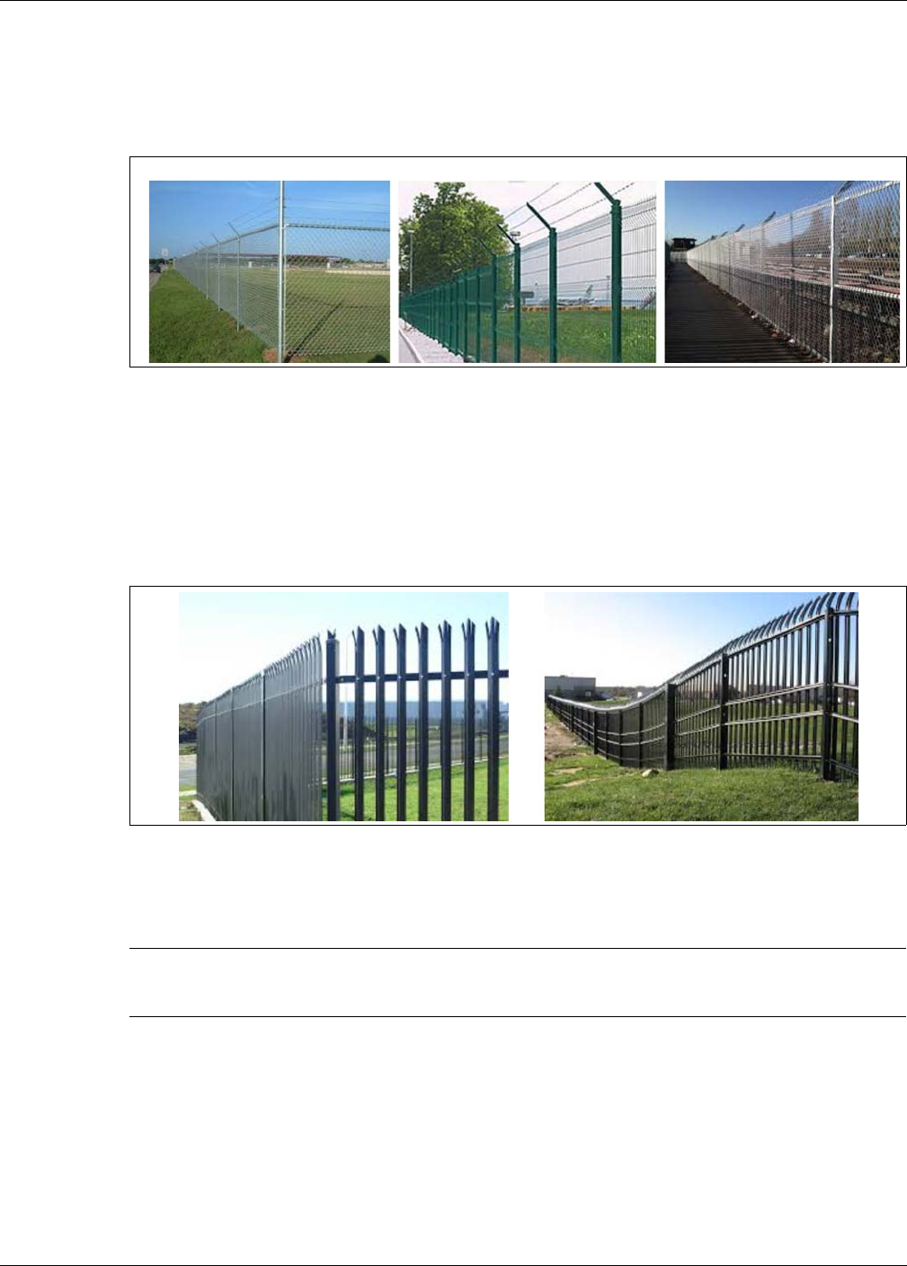
Standard flexible fence types
Chain-link fence
Chain-link fence is usually comprised of steel wires that are bent lengthwise into zig-zag patterns.
The zig-zag wires are vertically woven to form the characteristic diamond pattern. The fence fabric
is attached to fence posts approximately 3 m (10 ft.) apart. Tension wires are often used to stiffen
the fence fabric at the top, bottom and middle of the fence. Chain-link fences are available in
different heights and are sometimes vinyl coated.
Welded-mesh fences
A typical welded-mesh fence section consists of steel wire welded into a grid, with horizontal
spacing differing from vertical spacing. These fence sections are secured to fence posts and often
include top and bottom rails.
Note It is also possible to install luminaires by marking the fence posts,
drilling four holes and using self-tapping screws.
Fence structures
Senstar LM100 Product Guide Page 15
Expanded metal fences
Expanded metal mesh is typically comprised of a metal material with diamond shaped holes.
Expanded metal fences are available with a variety of diamond size openings and gauges that can
be attached to a typical fence framework of posts and rails.
Rigid fence types
Palisade fences
A typical palisade fence panel consists of metal pales fastened onto horizontal rails. These fence
sections are secured to fence posts which are securely anchored to, or into, the ground.
Climb-over deterrent hardware
Figure 4: Standard flexible fence types
Figure 5: Rigid fence (palisade)
Note The mounting height of the Senstar LM100 luminaires on the fence
posts may require adjustment to avoid contact with the climb-over
deterrent hardware.
chain-link welded-mesh expanded metal
Fence structures
Page 16 Senstar LM100 Product Guide
Barbed wire
Barbed wire outriggers must be secure to prevent movement due to environmental conditions.
Each barbed wire strand should be taut and tightly secured at each support. Any extension arms
or outriggers attached to post tops should have a tight press-fit or be spot-welded. Fasten and
secure any loose components.
Razor ribbon
The razor ribbon must be secured so that it does not move in the wind. Use bracing wires to
secure the coil and to prevent the razor ribbon from separating if it is cut (see Figure 7: ).
Gates
There are generally two types of gates used with fences, swinging gates and sliding gates. The
type of gate protection required is determined by:
• the type of gate
• the frequency of gate use
• when the system is active
Gates should consist of fence fabric on a rigid frame that includes horizontal and vertical bracing.
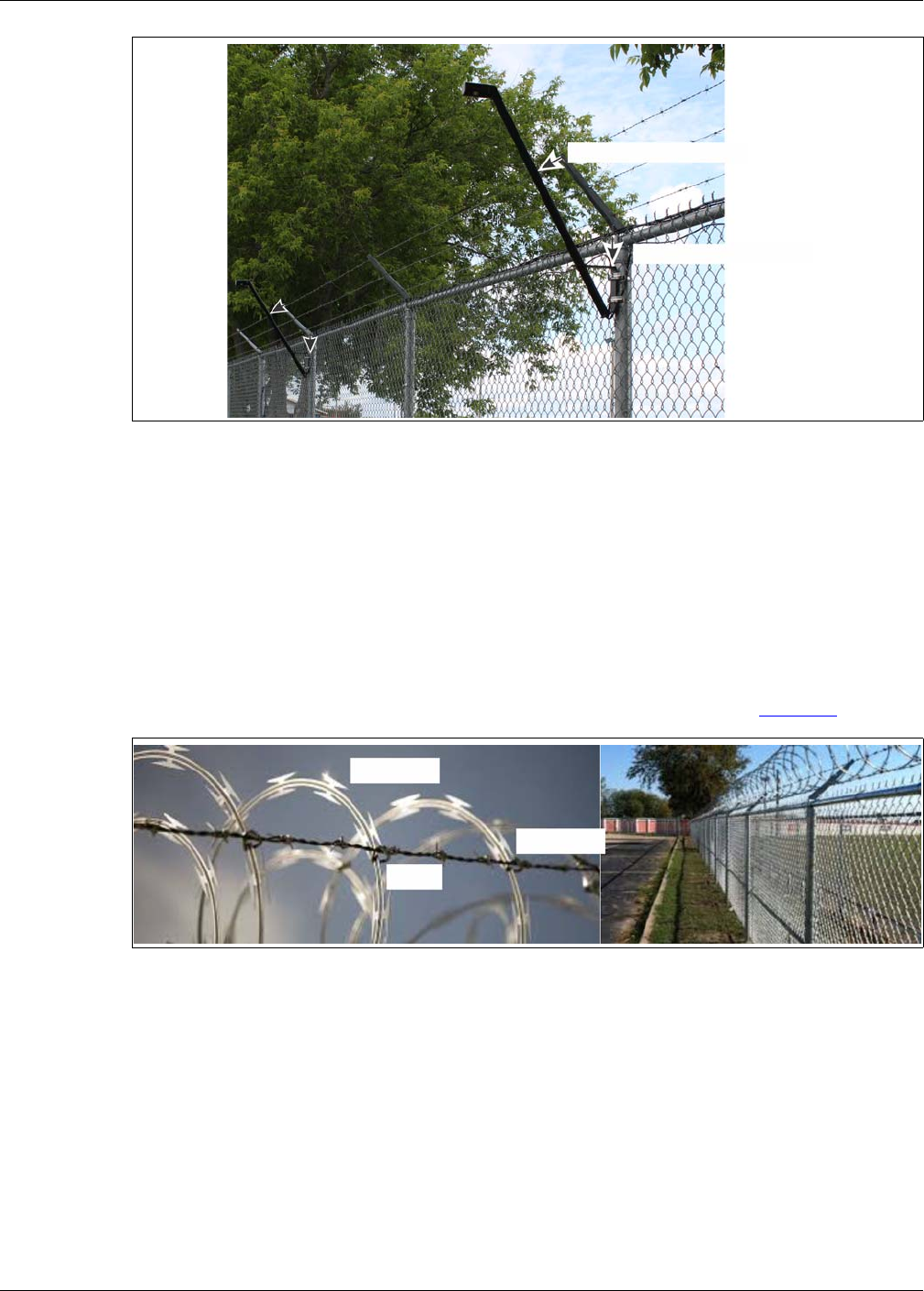
Figure 6: Avoiding contact with barbed wire
Figure 7: Razor ribbon
to avoid contact with the barbed wire
lower the luminaires mounting height
razor ribbon
bracing wire
wire tie

Site Survey
Senstar LM100 Product Guide Page 17
• Firmly attach all gate hardware accessories (minimum free-play).
• Make sure that double gates have travel stops (rigid anchors).
• Prevent locking hardware from moving in the wind.
• Prevent sliding gate track hardware, supports, guides, etc., from rattling in the wind.
There are two ways to protect gates with the Senstar LM100 system:
• The wireless gate sensor (WGS),
• An alternate technology (e.g., a microwave sensor).
Environment
For installations in environments which include hot sunny periods, install a sun shield to protect the
enclosure from direct sunlight, or install the enclosure in a shady area, or indoors. Extra care must
be taken at sites that experience strong winds on a regular basis. The fence must be well-
maintained to prevent any metal on metal contact caused by the wind. Any objects that can make
contact with the fence should be removed from the perimeter. Heavy vegetation (thick weeds,
brush, trees, etc.) should also be kept away from the fence. Vegetation should not touch or hang
over the fence fabric.
Site Survey
Conduct a site survey to ensure that site conditions are suitable, and to determine the number of
luminaires required to cover the perimeter fence. Also include any luminaires that will be used
exclusively for lighting purposes. The primary concern of the site survey is the condition of the
fence and gates.
Indicate the following on the site plan:
• The locations of existing structures (include fences, fence posts, heavy fence posts, gates,
buildings, roads, etc.).
• The locations of obstacles including vegetation and trees.
• The length of the fence that is being protected.
• The number of regular fence posts, heavy gauge fence posts, and the fence post spacing.
• Add any surface-mounted luminaires required at the site (in addition to fence-mounted).
Equipment layout
Depending on the height of the fence and the desired level of security, a luminaire is attached to
every fence post (3 m spacing) or every second fence post (6 m spacing). Regardless of the
regular spacing, each tension post, corner post and gate support post, should have a luminaire
attached as these types of posts are usually made of thicker steel and have a wider outside
diameter (OD) than regular fence posts. As a result of the heavier construction, these posts tend to
dampen vibrations.
Note The ambient temperature, as measured inside the gateway enclosure,
must be within the operational range of -40 to +70º C (-40 to +158º F).
Equipment layout
Page 18 Senstar LM100 Product Guide
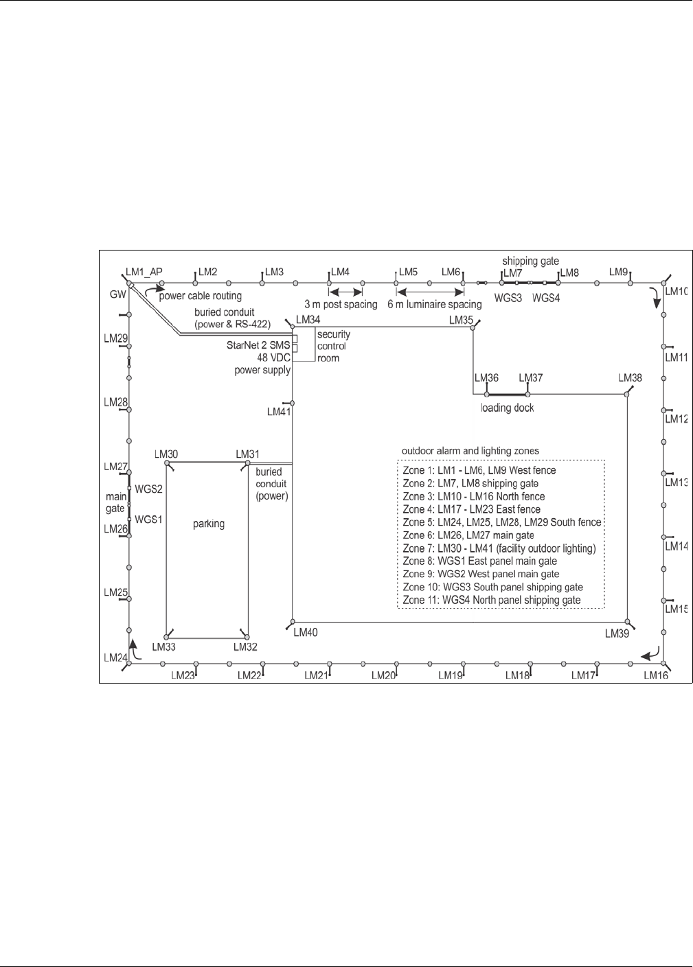
Use a site plan to mark the locations for the Senstar LM100 components:
• LM100 gateway - indicate the location and note the address for network based systems
• LM100 luminaire AP - indicate the location for the Access Point
• LM100 luminaires - indicate the location, the segment groupings, and zone boundaries (on the
site plan, number the luminaires in the order that will be used to form segments)
• Power supply - indicate the type and capacity of power supply and the power distribution plan
• Alarm communication wiring - relay output or network alarm communications
• Power cable - indicate the type and length of power cables that will be used
• Wireless Gate Sensor - the number of protected gates and the number of WGSs required to
cover them
Installation overview
Installing a Senstar LM100 system is a four step process:
1. Inspect and if necessary, repair the fence and the surrounding area.
2. Plan and design the system.
3. Install the Senstar LM100 gateway, luminaire AP and luminaires.
• ground rod
• power supply
• power cable
• data cable
4. Setup and calibrate the system.
Figure 8: Example site plan
Senstar LM100 Product Guide Page 19
2 Installation
Installing LM100 luminaires
Generally, a luminaire is attached to every second fence post (6 m spacing). In addition, all of the
heavier gauge fence posts should have a luminaire (tension posts, corner posts, gate support
posts). The luminaires should be installed on the side of the fence that faces the perceived threat.
Luminaires are installed so they are perpendicular to the fence line and plumb, with the head
facing directly downward.
The first step is mounting the gateway (or indicate the gateway’s installation location if it will be
installed later). Begin with the luminaire AP (the luminaire with a hard-wired connection to the
gateway).
At regular fence posts
Tools and equipment
• 8 mm (5/16 in.) nut driver or socket (low torque cordless drill with 8 mm socket recommended)
• ladder or scissor lift suitable for fence height
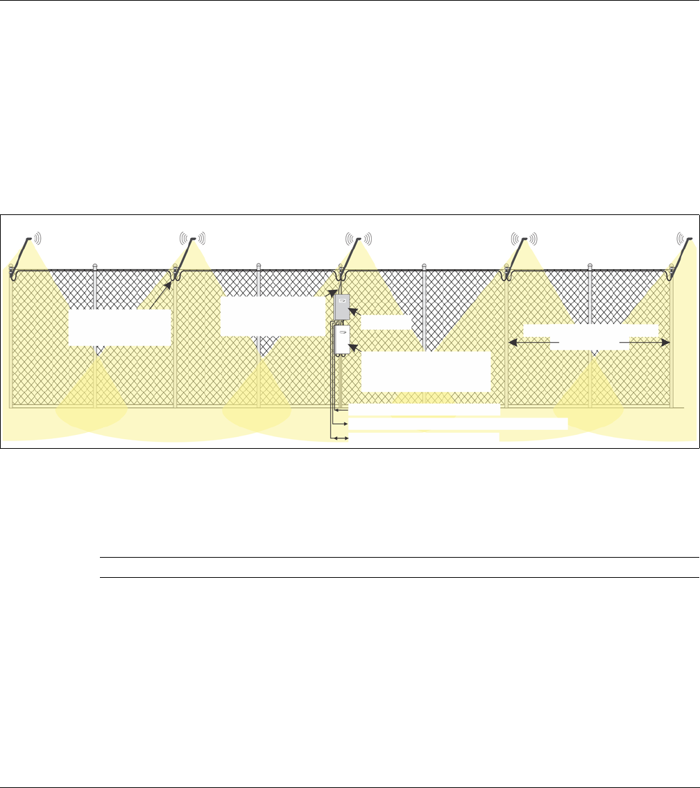
Figure 9: Senstar LM100 concept drawing
Tip Using a quick-grip clamp will simplify the installation of the luminaires.
2.4 GHz wireless mesh network (encrypted and supervised)
luminaire AP luminaire
gateway
48 VDC network
RS-485 connection
low voltage power
to luminaires typical luminaire spacing
6 m (20 ft.)
cable connection
(up to 100)
(1 required)
discrete inputs (light control)
discrete outputs (alarms / control points)
network interface to SMS
power supply for
gateway and luminaires
between gateway
and luminaire AP
Installing LM100 luminaires
Page 20 Senstar LM100 Product Guide
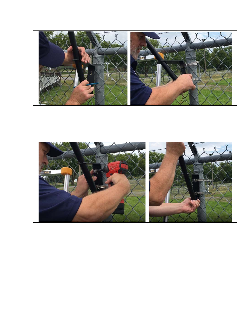
1. Hold the luminaire against the fence post as close to the top of the fence as possible without
making contact with the climb over barrier (minimum 25 mm {1 in.} separation between the
luminaire and the barbed wire) and mark the locations for the stainless steel post clamps.
2. Wrap the 2 post clamps around the luminaire and fence post to hold the luminaire in place.
3. Tighten the clamps so they fit into the slots on the luminaire’s bracket, and the luminaire is
perpendicular to the fence line and plumb to the ground.
4. If necessary, adjust the position of the luminaire on the fence post and finish tightening the
clamps until the luminaire is held securely against the fence.
5. Measure the space between the top of the fence post and the luminaire’s bracket and install
the remaining luminaires at the same height.
Figure 10: Luminaire installation steps 1 & 2
Figure 11: Luminaire installation steps 3 & 4
Installing LM100 luminaires
Senstar LM100 Product Guide Page 21
Figure 12: Luminaire installation example
Figure 13: 2.4 m (8 ft.) chain-link fence with luminaires
min. 2.5 cm separation
lower the mounting height
2 stainless steel clamps
power cable drip loop
to increase separation
Installing LM100 luminaires
Page 22 Senstar LM100 Product Guide
At corners or heavy gauge posts
Follow the directions for regular fence posts and install a luminaire on each heavy gauge fence
post.
Installing luminaires on welded-mesh fence
Mount the luminaire as high on the fence post as possible on the side of the fence that is facing the
threat.
Figure 14: Recommended luminaire spacing
Figure 15: Luminaire installation on heavy gauge posts
recommended luminaire spacing
cable ties secure power cable
to upper tension wire or top rail
drip loops
3 to 6 m (10 to 20 ft.)
regular spacing for
standard fence posts
reduced spacing for
heavy gauge posts
3 m (10 ft.)
single panel
6 m (20 ft.)
double panel
Installing LM100 luminaires
Senstar LM100 Product Guide Page 23
Installing luminaires on rigid fences
The technique used to install luminaires on rigid fences depends on the type, and brand, of fence.
Mount the luminaire as high on the fence post as possible on the side of the fence that is facing the
threat.
Figure 16: Welded-mesh fence with luminaires
Figure 17: Palisade fence with luminaire
back side front side
Impasse® II high-security
palisade fence
power cable
post clamps
drip loops
Installing LM100 luminaires
Page 24 Senstar LM100 Product Guide
Surface mounting luminaires
To surface mount a luminaire, hold the luminaire against the surface straight up and at the desired
height. Mark the locations of the four mounting holes on the surface. Drill the 4 holes and using
appropriate hardware, fasten the luminaire to the surface.
Power cable installation
Power cables are typically run along the top of the fence and daisy-chained from luminaire to
luminaire. The power cables pass through a grommet at the bottom of each luminaire and are
connected to the luminaire’s power wires with nylon-insulated, closed-end crimp connectors.
Figure 18: Residential palisade fence with luminaires
Figure 19: Surface mounting luminaires
1. Hold the luminaire against the surface and
mark the holes.
2. Drill the holes in the surface.
3. Using appropriate hardware, attach the
luminaire to the surface.
The luminaire includes four holes on the
bracket for surface mounting. Use 7 mm
(¼ in.) hardware that is appropriate for the
surface.
Installing LM100 luminaires
Senstar LM100 Product Guide Page 25
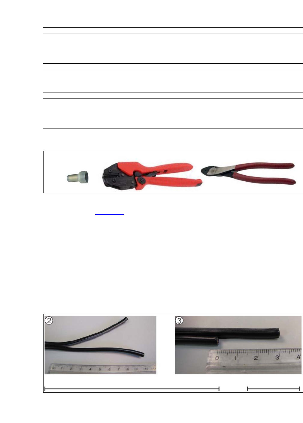
Tools and equipment
• crimp tool (see Figure 20: )
• wire stripper
• wire cutter
• linesman’s pliers
• needle-nose pliers
• ruler
• ladder or scissor lift suitable for fence height
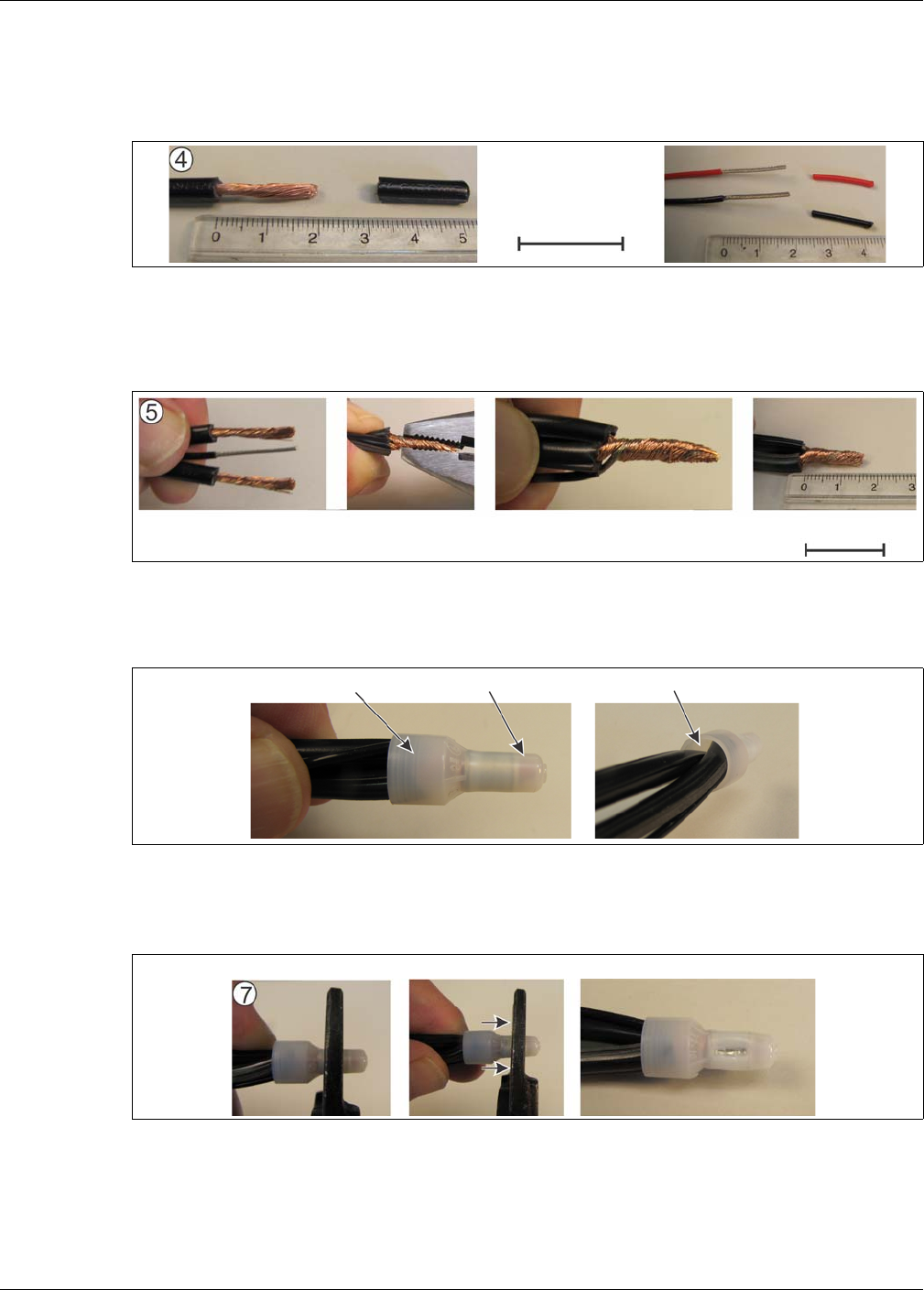
For daisy chain power cable wiring attach the power cable along the top of the fence:
1. Run the 2 sections of power cable from the top of the fence, down past the luminaire, and cut
the power cables 30 cm (1 ft.) below the base of the luminaire.
2. Separate the 2 conductors of the power cables for 10 cm (4 in) from the end.
CAUTION Use power cable that clearly distinguishes the 2 conductors to ensure
the correct polarity at each luminaire.
CAUTION Once the supplied grommet is inserted into the base of the luminaire it
is virtually impossible to remove without damaging the grommet.
Temporarily apply power and test each luminaire before inserting the
grommet.
Note Molex crimp tool p/n 64001-0600 is recommended for use with the
supplied Molex crimp connectors. However, the Klein model 1005 or
equivalent crimp tool is suitable for this application.
Note In harsh weather environments which include wind blown salt water
spray, Senstar recommends the use of a protective marine type
dielectric grease compound for the electrical connection to the
luminaires.
Figure 20: Power connection crimp tools
Figure 21: Power cable preparation
Molex SD-19160-001
closed-end connector
Molex 64001-0600 recommended crimp tool Klein 1005 suitable crimp tool
10 cm (4 in.) 1 : 1 scale 3 cm (1.2 in.) 1 : 1 scale
Installing LM100 luminaires
Page 26 Senstar LM100 Product Guide
3. Cut back the negative lead 3 cm (1.2 in.) to offset each power cable so the positive lead is
longer than the negative lead.
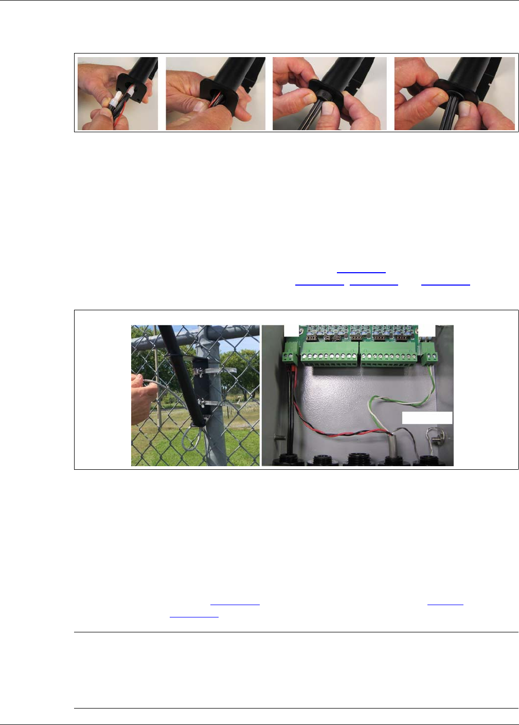
4. Remove 2 cm (3/4 in.) of the insulation from both conductors on each power cable, and from
both leads of the luminaire.
5. Tightly twist the 3 wires together to form a single conductor, and trim the single conductor back
to 15 mm (3/8 in.) (i.e., 2 negative conductors from power cables and black lead from
luminaire; 2 positive conductors from power cables and red lead from luminaire).
6. Insert the single conductor fully into the open-ended connector and verify through the
translucent connector before crimping.
7. Make the crimp. If the crimp tool you are using does not cover the full length of the internal
crimp ring make a second crimp.
8. Repeat this procedure for the power cables’ positive conductors and the red lead from the
luminaire.
9. Temporarily apply power to test the connection.
Figure 22: Stripping the leads
Figure 23: Forming a single conductor
Figure 24: Preparing the splice
Figure 25: Crimping the splice
2 cm (3/4 in.) 1 : 1 scale
15 mm (0.6 in.) 1 : 1 scale
insulation visible copper wires visible no visible wires
first crimp second crimp (if necessary) in-line crimps fully cover the crimp ring
Installing the LM100 gateway
Senstar LM100 Product Guide Page 27
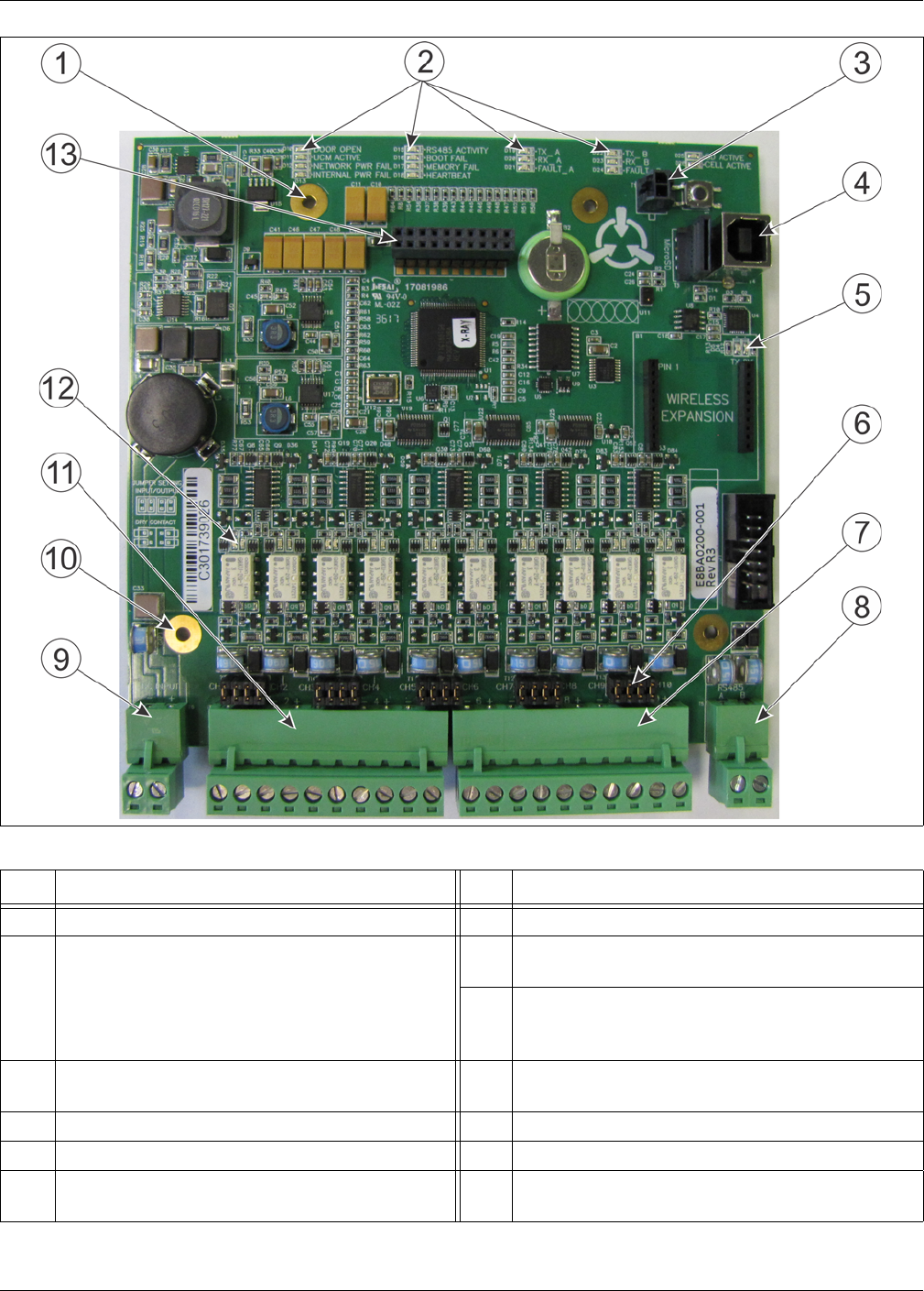
10. Push the 2 crimps up into the shaft of the luminaire, ensure that both of the power cables have
drip loops and press the grommet into the bottom of the shaft.
11. Attach the power cables neatly to the fence with UV resistant cable ties (P/N GH0916 - 1000
pieces) and continue making the power connections.
Installing the luminaire AP
The luminaire AP is usually attached to the same post as the gateway device. Mount the luminaire
AP in the same manner as the standard luminaires. The luminaire AP includes a 3 m (10 ft.) power
and data cable which is connected to the gateway device. Figure 27: shows an installed luminaire
AP and the AP connections to the gateway. See Figure 10: , Figure 11: and Figure 36: for
additional installation and connection details.
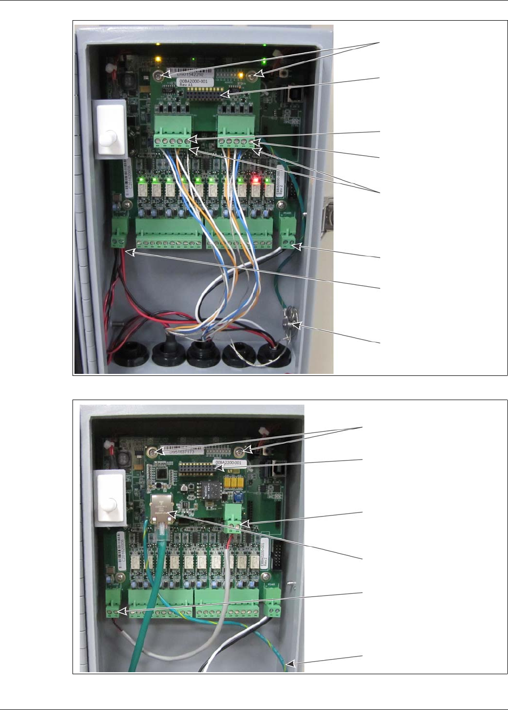
Installing the LM100 gateway
The gateway is shipped with two stainless steel clamps that are used for securing the enclosure to
a post (OD 4.5 to 12.7 cm). The hardware required to mount the enclosure on another type of
surface is customer-supplied. Figure 28: illustrates the gateway features and Table 1 includes
feature descriptions. Figure 30: shows a fence-mounted gateway.
Figure 26: Power connection crimp tools
Figure 27: Luminaire AP mounting and connection
Note The LM100 gateway can be installed up to 100 m (328 ft.) away from
the luminaire AP by splicing in a length of suitable power and data
cable. In this case, the 3 m cable that comes with the luminaire AP must
be shortened so the data and power splices can be fitted into the
luminaire AP’s shaft. Alternately, an outdoor-rated electrical junction box
can be used to protect the splice.
cable shield
RS-485
A B
DC power
_ +
luminaire AP
Installing the LM100 gateway
Page 28 Senstar LM100 Product Guide
Figure 28: Senstar LM100 gateway features
Item Description Item Description
1 Network interface card mounting hardware (X 2) 7 T8 - I/O ports 6 - 10
2 Activity LEDs - DOOR OPEN, UCM ACTIVE,
NETWORK POWER FAIL, INTERNAL POWER
FAIL, RS-485 ACTIVITY, BOOT FAIL, MEMORY
FAIL, HEARTBEAT, TXA, RXA, FAULT A, TXB,
RXB, FAULT B (LED ON = condition)
8 T5 - RS-485 connection to luminaire AP (green A
white B)
9 T6 - power input connection (- +) 12 to 48 VDC
(connect power supply leads and luminaire AP
power leads)
3 T1 - enclosure tamper input 10 gateway circuit card assembly (CCA) mounting
hardware (X 2)
4 T2 - USB connection to UCM PC 11 T7 - I/O ports 1 - 5
5 UCM activity LEDs (TX, RX) 12 I/O port activity LEDs - LED ON = port active
6 Input/Output configuration jumpers 13 T2 - Expansion header for network interface card,
gate sensor receiver and I/O card
Table 1 Gateway feature descriptions
Installing the LM100 gateway
Senstar LM100 Product Guide Page 29
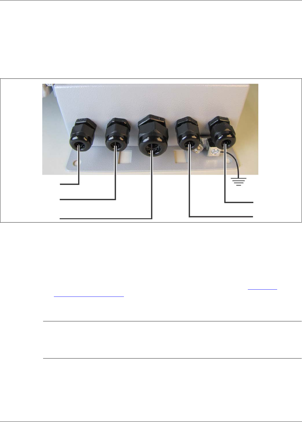
Cable entry ports
The bottom of the gateway enclosure includes five cable entry ports fitted with compression glands
for the power cable, I/O cable, and RS-485 cable. The central port includes a 12.7 mm (1/2 in.)
cable gland, which fits cables ranging between 4.3 - 11.4 mm (0.17 to 0.45 in.). The other four
ports (two on each side) provide 9.5 mm (3/8 in.) compression glands, which fit cables ranging
between 2.9 - 7.9 mm (0.115 to 0.312 in.). Five plugs are included for instances where not all of
the cable entry ports are required. The bottom of the enclosure also includes an exterior ground
lug for the earth ground connection.
Free-standing or fence post mounting the enclosure
• Install the gateway near eye-level on the secure side of the perimeter.
Mounting the enclosure away from the protected fence on the secure side of the perimeter can
help prevent tampering.
• Mount the enclosure with the cable entry ports on the bottom toward the ground.
• Install an approved earth ground at the gateway location, if required (see Grounding
considerations on page 13).
• If razor ribbon is installed along the bottom of the fence, mount the gateway on the secure side
of the perimeter, away from the fence and razor ribbon.
Figure 29: Cable entry recommendations
CAUTION For installations in environments which include hot sunny periods,
Senstar recommends that a sun shield be installed to protect the
enclosure from direct sunlight, or that the enclosure be installed in a
shady area. The maximum operating temperature, as measured
inside the enclosure, is 70º C (158º F).
RS-485 cable
network data cable
network data cable
12 to 48 VDC
I/O port wiring
earth ground
(luminaire AP)
Installing the LM100 gateway
Page 30 Senstar LM100 Product Guide
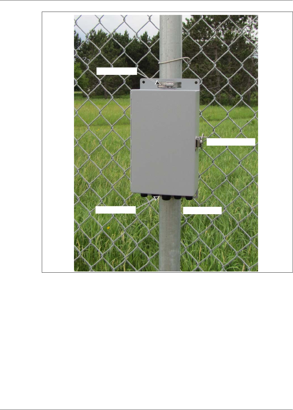
Figure 30: Fence-mounted gateway
lockable door latch
upper clamp
lower clamp I/O cable ports
Installing the LM100 gateway
Senstar LM100 Product Guide Page 31
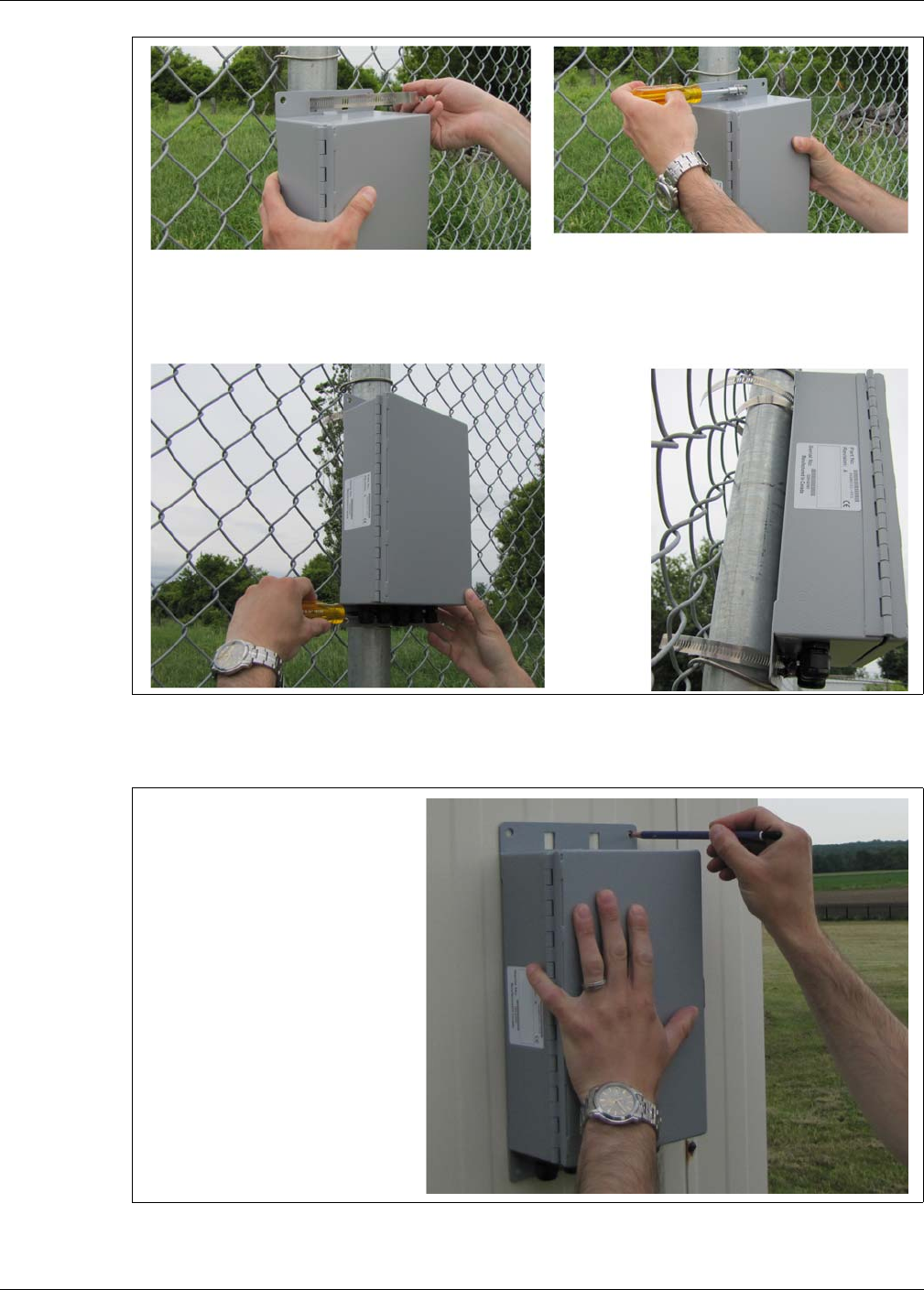
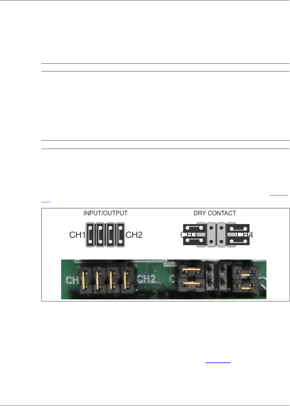
Surface mounting
Figure 31: Post-mounting the enclosure (on the fence)
Figure 32: Surface-mounting the enclosure
1. Hold the enclosure against the fence at the specified installation location.
2. Feed the end of the stainless steel clamp through an upper flange slot, around the fence post, and back
through the second slot.
3. Insert the end of the stainless steel clamp into the gear mechanism and tighten the screw.
4. Repeat this with the second clamp on the lower flange at the bottom of the enclosure.
1. Hold the enclosure against the
2. Drill 4 holes in the mounting surface.
3. Using appropriate hardware, mount
mounting surface, and mark the
positions of the 4 mounting holes.
the enclosure.
Use 7 mm (¼ in.) hardware.
Installing the LM100 gateway
Page 32 Senstar LM100 Product Guide
Grounding
The gateway requires a single ground reference. Connect the ground lug on the bottom of the
enclosure to an approved earth ground at the gateway’s location. The earth ground connection
must be stable and noise free. An improper or unstable earth ground can induce noise in the
gateway. Do not use the fence structure as an earth ground. Avoid sharp bends in the ground wire.
I/O ports
The LM100 gateway includes ten I/O ports that can be configured as either inputs or outputs in any
combination. The I/O ports are accessed through removable screw terminal blocks. Each port has
an associated LED, which indicates when the port is active (LED ON = port active). The optional
dry contact input card includes four additional inputs and the optional relay output card includes
four additional relays to supplement the I/O on the gateway.
I/O port jumpers
Each I/O port includes a pair of configuration jumpers which are set according to the intended use
of the port. For ports that will be configured as outputs and will source power to an external device,
and for all inputs, install the shunts on the headers. For ports that will be configured as outputs but
will not source power (dry contact outputs) park the shunts on a single pin, as indicated in Figure
33: .
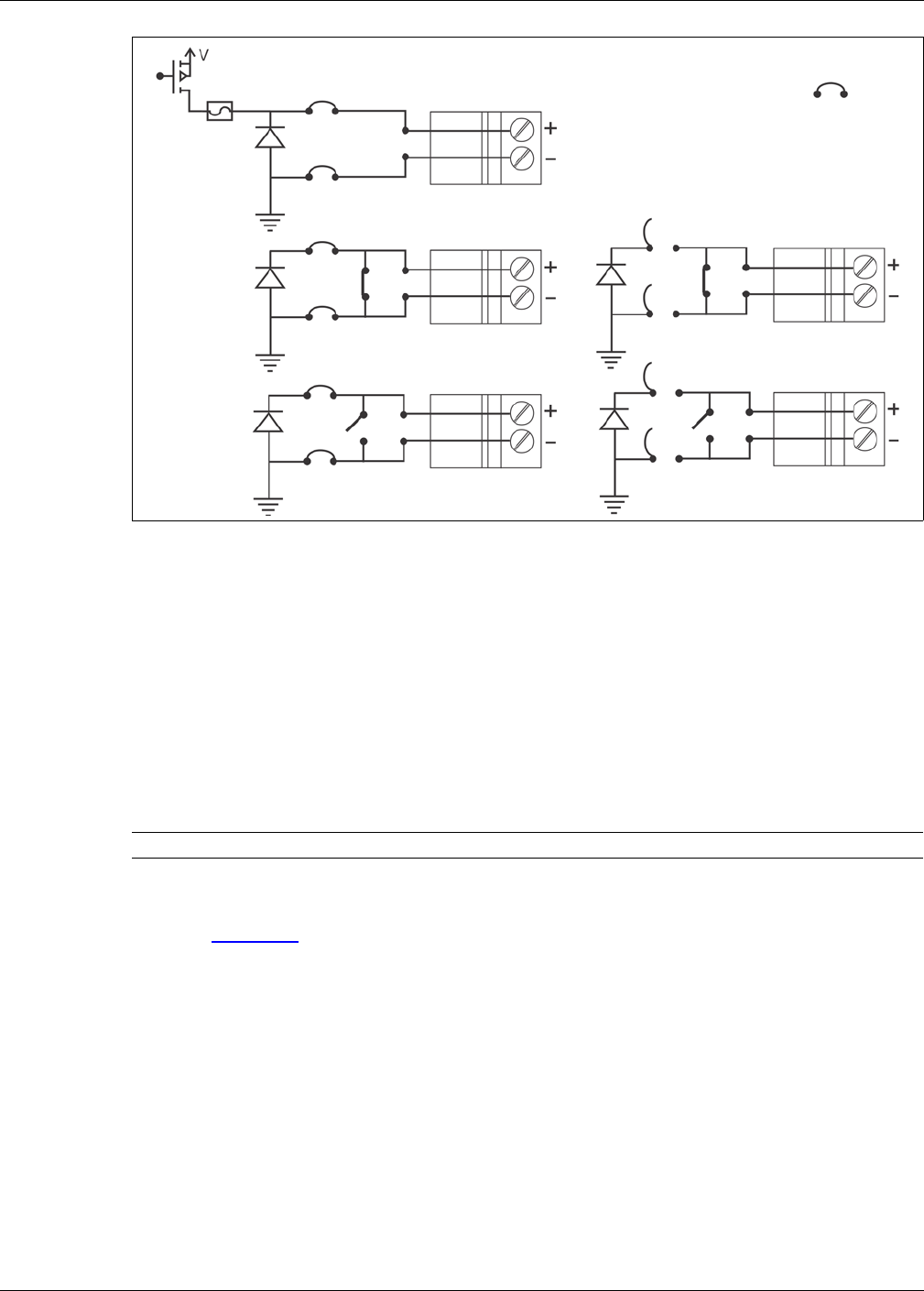
Outputs
The gateway’s relay outputs can source up to 100 mA at the same voltage as the gateway’s input
power in the high side drive configuration. The relays can also be configured to sink up to 100 mA
as Form A (normally open) or Form B (normally closed) contacts. The capability to source power
depends on the capacity of the connected power supply. The gateway’s relays can also be
configured as Form A or Form B dry contact outputs (no power). Figure 34: illustrates the
gateway’s five selectable output schematics.
Note Consult the local electrical code for grounding information.
Note The gateway can use either an input card or an output card, not both.
Figure 33: Gateway I/O port jumper settings
voltage sourcing outputs and dry contact inputs dry contact outputs
Installing the LM100 gateway
Senstar LM100 Product Guide Page 33
Relay contact ratings
The gateway’s relays are latching, and are rated for 30 V @ 1 A max. In Remote control mode, you
can configure the relays as latching (ON by command, OFF by command), in flash mode (ON-
OFF-ON-OFF... by command, then OFF by command), or pulse mode (ON for a period, then
OFF). For flash and pulse modes, the relay Active/Inactive times are selectable.
In Local control mode the relays remain active for the event’s duration or for the selectable Hold
Time, whichever is longer.
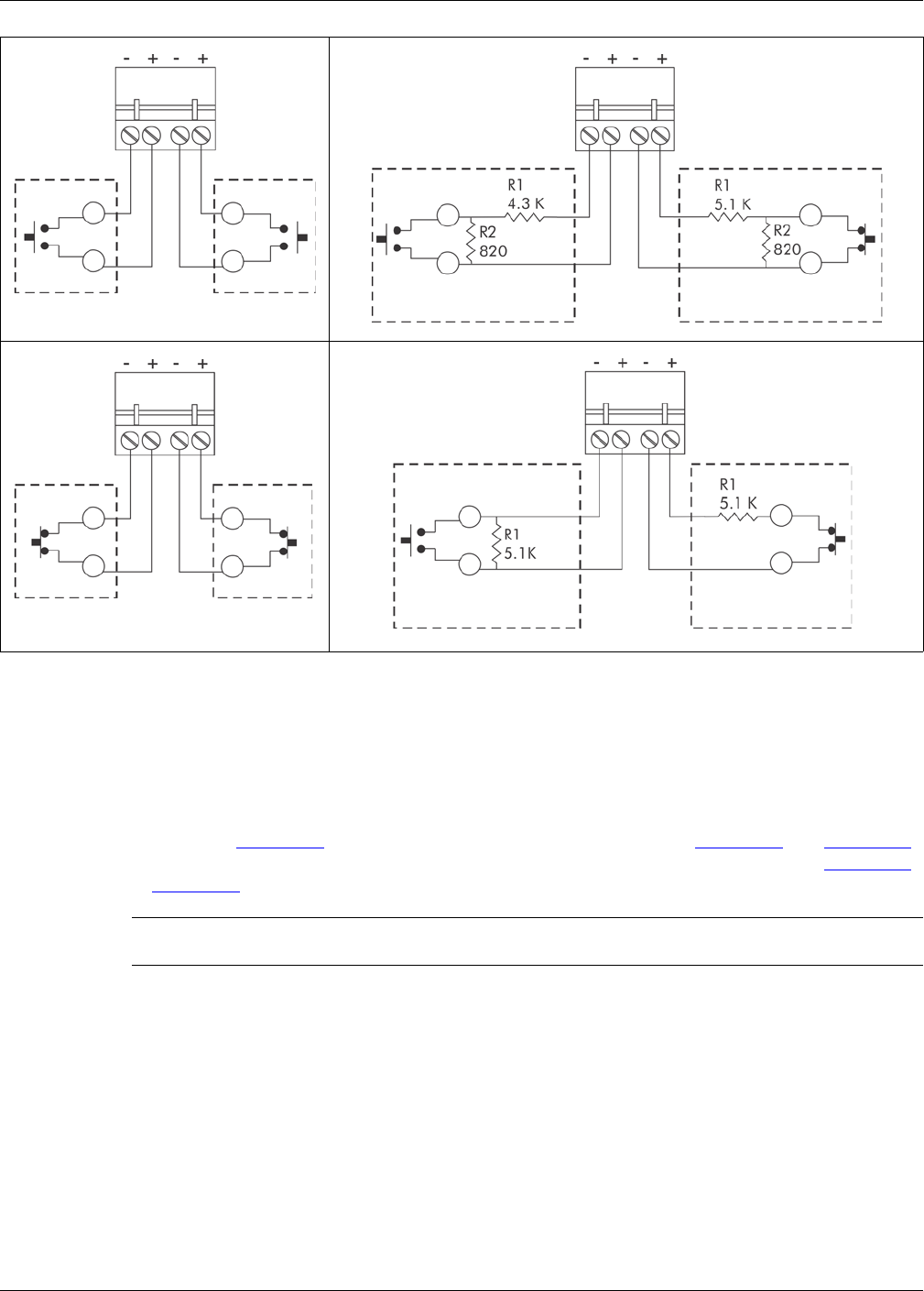
Auxiliary inputs
I/O points defined as inputs are voltage sensing inputs. The gateway determines an input’s status
via an internal reference voltage, and the configuration of the contact closures and supervision
resistors. Figure 35: provides wiring diagrams for auxiliary device inputs.
In Local control mode the inputs are used to activate luminaire zones. When the input goes high,
the specified luminaire zone is activated.
In Remote control mode the AUX inputs serve as inputs to the host SMS for reporting the status of
auxiliary security equipment.
Figure 34: Gateway output schematics
CAUTION The contact closure inputs to the gateway MUST be voltage-free.
power sourcing output
dry contact output
shunt
Form A
Form B
high side drive
Form A
Form B
power sinking output
power sinking output dry contact output
Installing the LM100 gateway
Page 34 Senstar LM100 Product Guide
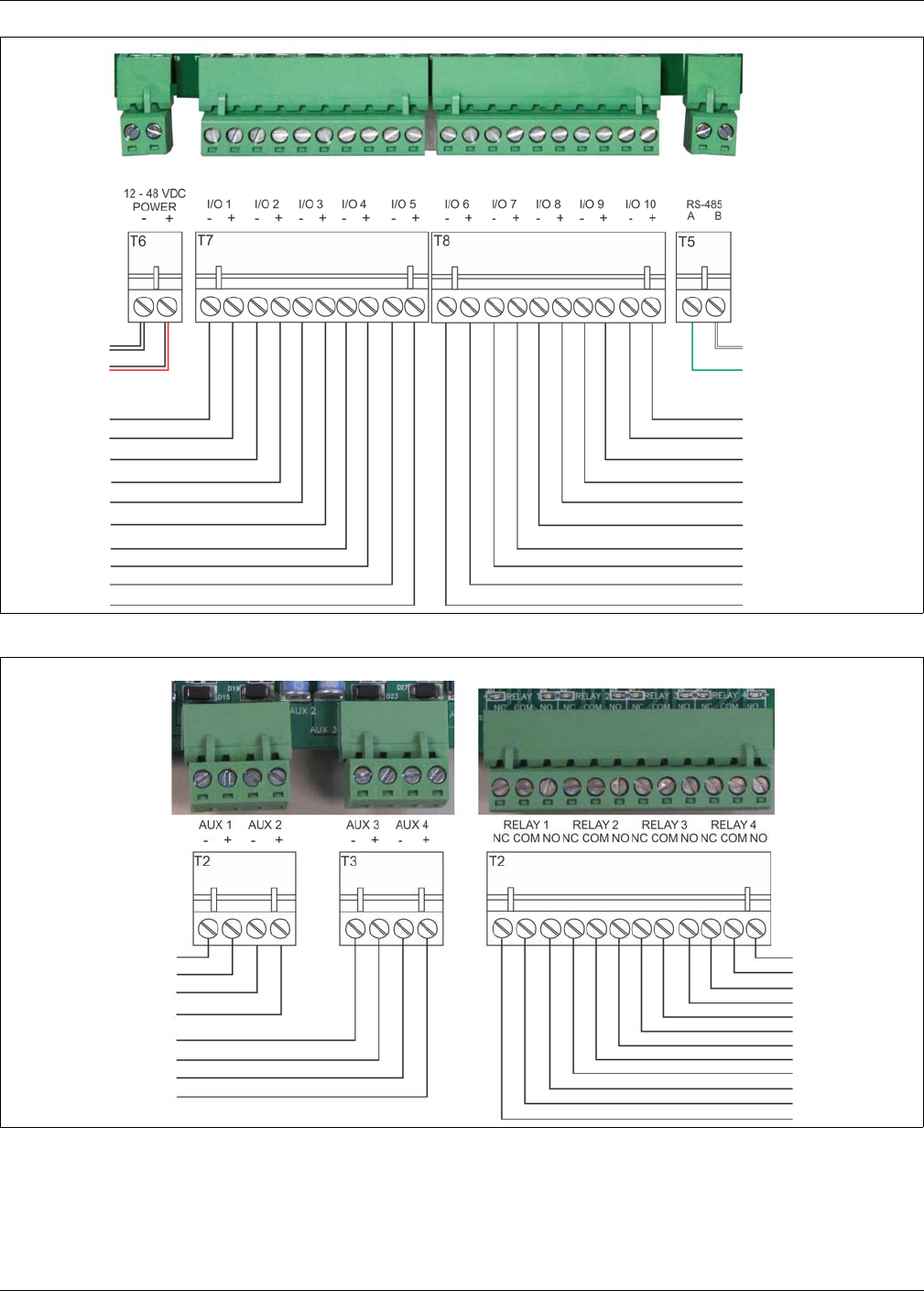
Gateway wiring connections
LM100 gateway wiring connections are made on removable terminal blocks. The screw terminals
accept wire sizes from 12 to 24 AWG, with a 6.4 mm (¼ in.) strip length. Remove the terminal
blocks to make the wiring connections. Reinstall the blocks after the connections are complete,
and verified. Figure 36: shows the gateway input wiring connections. Figure 36: and Figure 38:
illustrate the gateway wiring connections and the connections to the I/O option cards. Figure 38:
to Figure 43: show the Silver Network wiring options.
Figure 35: Gateway input wiring examples
Note See instruction sheet 00DA1503 for information about installing the
optional relay output card and dry contact input card.
NO inputs unsupervised
NO input
dual resistor supervision
NC input
cut and short supervision cut and short supervision
dual resistor supervision
NC inputs unsupervised
single resistor supervision single resistor supervision
cut supervision short supervision
NO input NC input
Installing the LM100 gateway
Senstar LM100 Product Guide Page 35
Figure 36: gateway wiring diagram
Figure 37: Option card wiring diagram
T6 DC power input T5 RS-485
- VDC
INPUT POWER
RS-485
T7 I/O ports 1 - 5 T8 I/O ports 6 - 10
(white wire from AP)
I/O 10 +
I/O 10 -
I/O ports 6 - 10
I/O 9 +
I/O 9 -
I/O 8 +
I/O 8 -
I/O 7 +
I/O 7 -
I/O 6 +
I/O 6 -
I/O 1 -
I/O 1 +
I/O ports 1 - 5
I/O 2 -
I/O 2 +
I/O 3 -
I/O 3 +
I/O 4 -
I/O 4 +
I/O 5 -
I/O 5 +
(green wire from AP)
(12 to 48 VDC)
+VDC
(black wire from AP)
(red wire from AP)
ROC outputs
DRIC inputs
auxiliary inputs
-
+
OPT input 1
-
+
OPT input 2
OPT 4 NO
OPT 4 COM
OPT 4 NC
-
+
OPT input 3
-
+
OPT input 4
OPT 3 NO
OPT 3 COM
OPT 3 NC
OPT 2 NO
OPT 2 COM
OPT 2 NC
OPT 1 NO
OPT 1 COM
OPT 1 NC

Installing the LM100 gateway
Page 36 Senstar LM100 Product Guide
Silver Network wiring connections
Silver Network specifications
• Data rate - fixed 57.6 k bps
• Maximum 60 devices spread over up to 4 independent network loops
• Two communication Channels (Side A, Side B)
• Response time - 1 second, or less from alarm source to Network Manager (per loop)
• Network termination - not required
• Transmission media/maximum separation distances between gateways:
• RS-422 copper wire - 1.2 km (0.75 mi.) - 2 pairs per Channel
• Multi-mode fiber optic cable (820 nm) - 2.2 km (1.4 mi.) - 2 fibers per Channel - optical
power budget 8 dB
• Single-mode fiber optic cable (1310 nm) - 10 km (6.2 mi.) - 2 fibers per Channel - optical
power budget 8 dB
• Ethernet - Category 5 cable, 100 m between PoE switch and gateway location
Note A network interface card is required on the gateway to enable Silver
Network communications.
Note Use low capacitance shielded twisted pair data cable for RS-422,
62.5/125 multi-mode fiber optic cable,
9/125 single-mode fiber optic cable, and
Category 5 Ethernet cable.
The maximum separation distances require high quality transmission
media and sound installation practices.
CAUTION Both the gateway and the network interface cards contain static
sensitive components. Follow proper ESD handling procedures when
handling the cards.
Ensure the expansion header on the NIC is properly lined up and fully
seated in T2 on the gateway.
Installing the LM100 gateway
Senstar LM100 Product Guide Page 37
Figure 38: Silver Network RS-422 wiring connections
Figure 39: Silver Network Ethernet (PoE) wiring connections
expansion header T1
use single point grounding
(plugs into T2 on gateway)
mounting hardware (X 2)
A-side comms
B-side comms
(connect one end of cable shield,
(on solder side)
NIC ground connection
to ground, trim the other end
and leave it disconnected)
gateway power input
luminaire AP power connection
luminaire AP RS-485 connection
luminaire AP cable shield
ground connection
expansion header T1
T6 gateway power input
(plugs into T2 on gateway)
NIC mounting hardware (X 2)
T2 PoE NIC DC output (12 VDC)
Ethernet network connection
(on solder side)
PoE NIC ground
Installing the LM100 gateway
Page 38 Senstar LM100 Product Guide
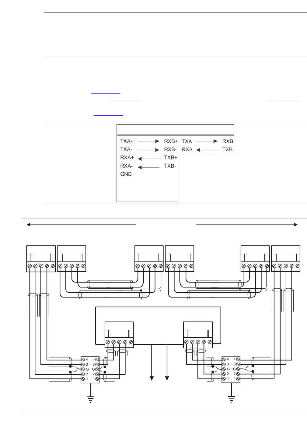
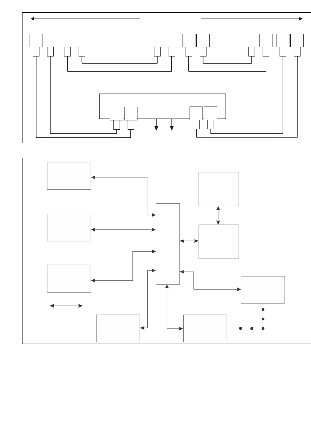
Silver Network data path connections
In the standard Silver Network setup, a point to point loop configuration is used for network
communications. Figure 40: shows the network connections for the RS-422 and fiber optic
communication options. Figure 41: illustrates an RS-422 based Silver Network and Figure 42:
shows a fiber optic based Silver Network. Silver Network’s using Ethernet communications use a
star configuration. Figure 43: illustrates an Ethernet based Silver Network (Star configuration).
Note The PoE NIC typically receives power over its Ethernet connection. It
provides power to the gateway through T6, the gateway power input.
The gateway then supplies power to the NIC through the expansion
header. If the PoE NIC does not receive power over its Ethernet
connection, the gateway must have another source of DC power
connected to T6.
Figure 40: Silver Network data connections (loop configurations)
Figure 41: Silver Network RS-422 wiring diagram
RS-422 Fiber Optic
(use single point
grounding, connect one
end of cable shield; trim
the other end and leave
it disconnected)
11
223344
55
RXB+
RXB-
GND
TXB+
TXB-
RXA+
RXA-
GND
TXA+
TXA-
11
223344
55
12345 12345
1
1
2
2
3
3
4
4
5
5
1
2
3
4
5
1
2
3
4
5
12345 12345
RXB+
RXB-
GND
TXB+
TXB-
RXA+
RXA-
GND
TXA+
TXA-
RXB+
RXB-
GND
TXB+
TXB-
RXA+
RXA-
GND
TXA+
TXA-
RXA+
RXA-
GND
TXA+
TXA-
12345
RXB+
RXB-
GND
TXB+
TXB-
12345
maximum 60 devices
max. distance between devices = 1.2 km (3/4 mile)
first device second device last device
shield shield
shield shield
shield
shield
NOTE: Use single point grounding - connect one end of the cable shield, trim the other end and leave it disconnected.
Network Interface Unit
lightning
arrestors
lightning
arrestors
to Network Manager
Installing the LM100 gateway
Senstar LM100 Product Guide Page 39
Figure 42: Silver Network fiber optic wiring diagram
Figure 43: Silver Network Ethernet wiring diagram
TXB RXBTXA RXA
TXB RXB TXA RXA
TXB
RXB
TXA
RXA
TXB
RXB
TXA
RXA
maximum 60 devices
first device second device last device
Network Interface Unit
to Network Manager
maximum distance between devices
multi-mode fiber optic = 2.2 km (1.4 miles)
single-mode fiber optic = 10 km (6.2 miles)
maximum 60 devices
first device
second device
last device
Network
maximum distance
third device
fourth device fifth device
Manager
computer
security
management
system
computer
between device
and PoE switch
100 m (328 ft.)
Category 5 Ethernet cable
class 3
PoE
switch

Installing the LM100 gateway
Page 40 Senstar LM100 Product Guide
Power supply connections
The LM100 gateway operates on 12 to 48 VDC. The power connection is made on removable
terminal block T6. In most cases, the luminaire AP’s power leads are also connected to T6.
Network power supply
When using a centrally located network power supply, ensure that the supply has sufficient
capacity if the gateway’s outputs will source power to auxiliary devices.
Local power supply
It is possible to use a local DC power supply when a source of AC power is readily available near
the gateway. The DC power supply must be installed in its own weatherproof enclosure. The local
supply can be mounted on the same post as the gateway to keep the wire runs to a minimum.
Power over Ethernet
For power over Ethernet, a class 3 PoE switch is required. In this configuration, minimum Category
5 cable must be used and the maximum distance between the gateway and the PoE switch is
100 m (328 ft.). Each gateway receiving PoE requires an earth ground connection. The PoE NIC
can also supply power for the luminaire AP. Figure 39: shows a PoE NIC mounted on the gateway
CCA.
Backup power
Senstar recommends that the Senstar LM100 system be powered from an uninterruptible power
supply (UPS). Connect AC mains to the UPS and the UPS to the DC power source. In this way, if
AC power is interrupted, the LM100 can operate on battery power while AC power is being
restored.
WARNING! DO NOT bring AC mains power into the gateway enclosure. If a local
power supply is being used, it must be installed in its own weatherproof
enclosure. Consult the local electrical code for information about the
connection of AC mains to your power supply.
Note When a central low voltage power supply is being used for primary
power, it should be powered from an uninterruptible AC power source.
Note See Figure 28: Figure 29: and Figure 36: for power connection details.
CAUTION The PoE NIC is intended to supply power only to the LM100 gateway
device on which it is mounted and the luminaire AP. Do not attempt to
power additional luminaires, or an auxiliary device, with the PoE NIC.
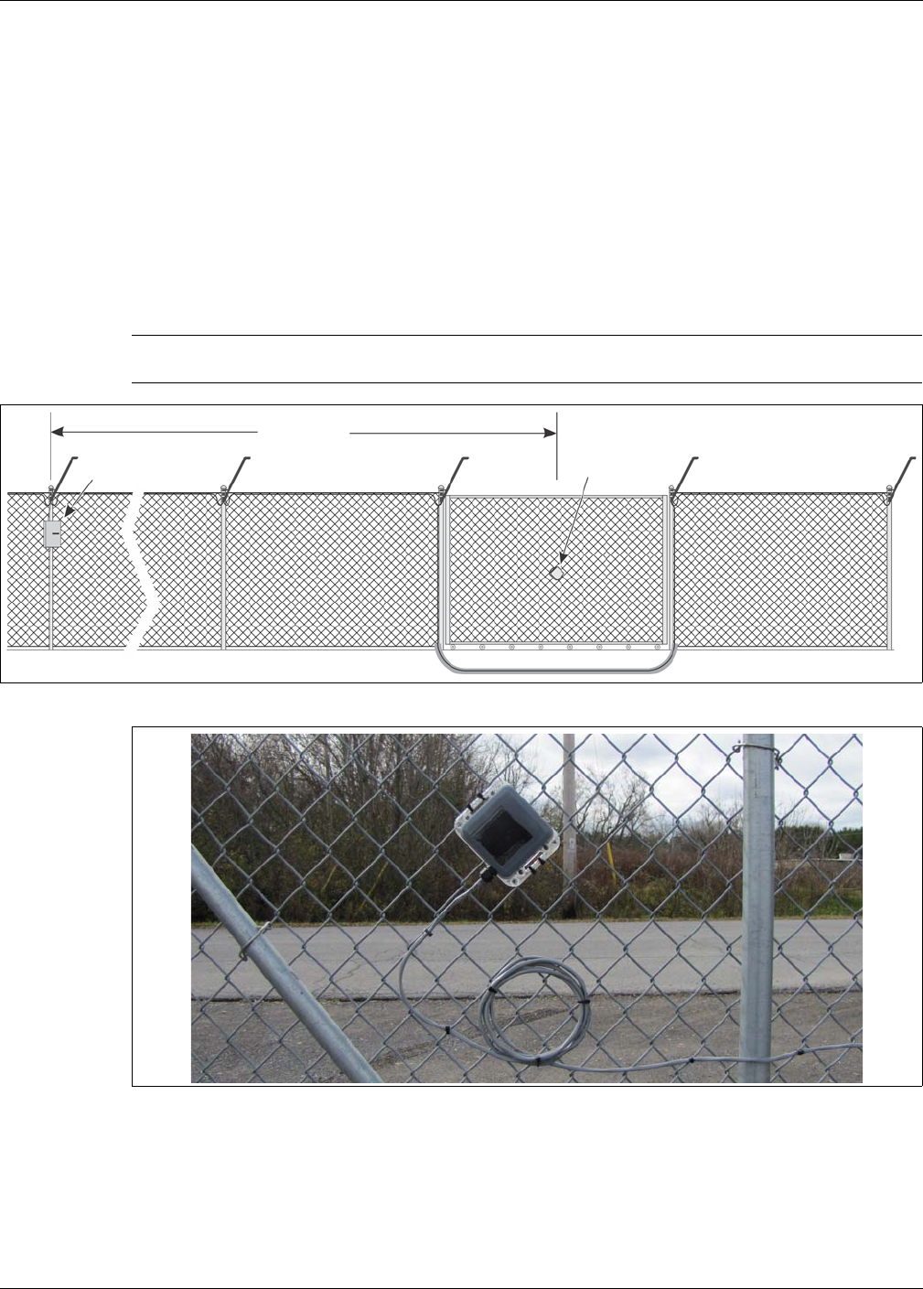
Using the wireless gate sensor
Senstar LM100 Product Guide Page 41
Using the wireless gate sensor
The wireless gate sensor (WGS) operates in conjunction with the Senstar LM100 system to
provide RF-based wireless security protection for gates. The WGS is comprised of two
components. The wireless gate sensor module (GSM) is attached to the gate. The GSM analyzes
signals picked up from the fence fabric on the gate and will transmit an alarm when it detects
vibration, motion, or positional changes. A wireless gate sensor receiver (GSR) mounted on the
LM100 gateway circuit card assembly (CCA) receives the transmission and passes on the alarm
signal to the gateway. Alarm data communications are via the gateway over the Silver Network or
by contact closures.
Note See E7DA0103 Wireless Gate Sensor for information on installing and
configuring the WGS.
Figure 44: Wireless Gate Sensor example
Figure 45: Solar powered Wireless Gate Sensor with magnetic gate contact
up to 300 m
gateway with Gate Gate Sensor
Sensor Receiver Module

Using the wireless gate sensor
Page 42 Senstar LM100 Product Guide
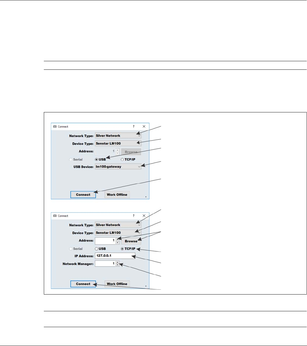
Senstar LM100 Product Guide Page 43
3 Calibration & setup
The Universal Configuration Module
The Universal Configuration Module (UCM) is a Windows based software application, which
serves as the calibration, setup and maintenance tool for the Senstar LM100 system. The UCM
communicates with the gateway locally through a USB connection, or remotely via the Silver
Network Manager. When the UCM software starts, the Connect window displays:
Note Consult the online help for detailed information on UCM operation.
Figure 46: Connecting the UCM
Tip Save UCM files with a meaningful name, which includes the time and
date. The files can then be reopened at a later time (Work Offline).
USB direct connection
TCP/IP connection via Network Manager
in the Network Type: field select the network to which
you are connecting (Silver for Senstar LM100)
in the Device Type: field select the device (Senstar LM100)
select the connection type (i.e., USB)
select the connect button to establish the connection
in the Network Type: field select the network to which you
are connecting (Silver for gateway)
to connect via the Silver Network Manager, use the Browse
button to locate the gateway address OR use the Address
field to specify the gateway address
select the connection type (i.e., TCP/IP)
enter the IP address of the Network Manager PC (if the NM and
UCM are on the same PC, enter 127.0.0.1 as the IP Address)
specify the ID number assigned to the Network Manager
select the connect button to establish the connection
in the Device Type: field select the device (Senstar LM100)
select the arrow to display the connected USB device
(i.e., lm100-gateway)
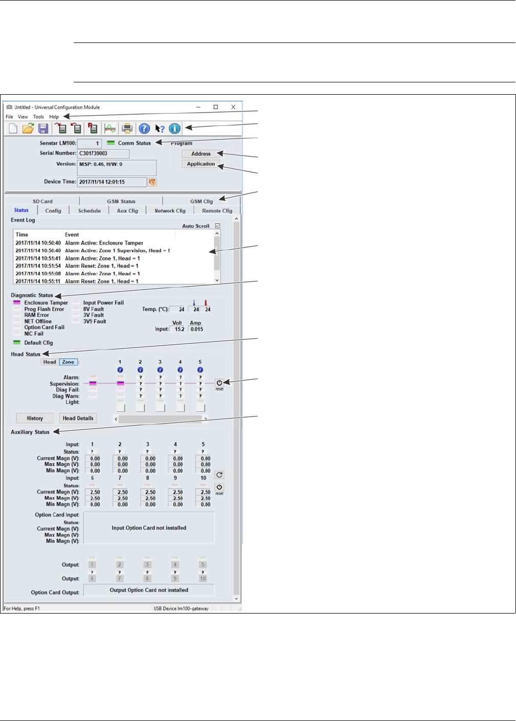
The Universal Configuration Module
Page 44 Senstar LM100 Product Guide
When you select the Connect button, the UCM status window displays.
The following table includes the Senstar LM100 configuration parameters along with a brief
description. The Sensor Head Configuration settings apply to all of the installed luminaires, unless
the parameter is assigned to a specific segment or zone.
Note Refer to the UCM help file and the appropriate section in this document
for additional details on configuring the Senstar LM100 and UCM
operation.
Figure 47: UCM Status window
UCM menu selection
UCM fast access buttons
details about the connected gateway
(green Comm Status Led indicates active UCM connection)
select Address to set the gateway’s Silver network address)
select Application to update the gateway or luminaire firmware
select a UCM tab to display or configure the selected properties
the Event Log contains the 500 most recent Events since the UCM
was connected
the Diagnostic Status field displays the results of ongoing self-tests
the Head Status field displays information about the luminaires on
the wireless mesh network
the Auxiliary Status field displays information about the gateway’s I/O
use the reset button to set the head supervision for their current
installation locations

The Universal Configuration Module
Senstar LM100 Product Guide Page 45
Configuration parameter Descriptions
Address Use the Address button to assign Silver Network based Senstar
LM100 gateway’s a unique network address (1 - 60)
Application Use the Application button to update the LM100 gateway or
luminaire firmware
Config tab (sensor head configuration, settings apply to all luminaires)
Comm Channel If 2 or more Senstar LM100 systems operate within 400 m (1300 ft.)
of each other, they must use different Comm Channels to prevent
mutual interference
Target Filter (Hz) There are 2 Target Filters for adjusting the frequency response of
the luminaires (2 - 400 Hz)
The high pass filter is used to screen out low frequency vibrations
such as the fence motion caused by wind sway and loose fence
fabric
The low pass filter is used to screen out high frequency vibrations
such as the thermal expansion and contraction of palisade fences
Event Window (sec) Sets the time period after an Event is recorded before the next Event
can be recorded (0.5 - 10 seconds)
Used to prevent vibrations caused by a single Event from being
recorded as subsequent Events
Event Count When the detection signal exceeds the Threshold setting an Event is
recorded and added to the Event Count;
When the number of recorded Events reaches the Event Count
setting an alarm is declared (1 - 10)
Alarm Window (sec) Sets the time period after the first Event is recorded in which the
specified number of Events must occur to trigger an alarm
(1 - 99 seconds)
Each time the Event Count is incremented, the Alarm Window time
begins to count down from the set value;
If a subsequent Event occurs before the Alarm Window time lapses
the Event Count is incremented and the Alarm Window time begins
to count down from the set value;
If the Event Count setting is reached before the Alarm Window time
expires, a sensor alarm is declared;
The Alarm Window resets after each Event;
If the Alarm Window time lapses before a subsequent Event is
recorded both the Alarm Window time and the Event Count are reset
Normal Light Control - Set the luminaire brightness for routine scheduled operation
Light Level Set the Light Level (brightness) for regularly scheduled light
activation (not alarm activation)
Auto Light Control - Set the luminaire response to alarm conditions
Mode Specify the luminaire’s lighting activity in response to a sensor alarm
(e.g., strobe the luminaire that recorded the alarm and activate all
luminaires that are assigned to the same zone)
Duration (min) The number of minutes the activated luminaires will remain in alarm
mode following an alarm (1 - 15 minutes)
Light Level Set the Light Level (brightness) for alarm response light activation

The Universal Configuration Module
Page 46 Senstar LM100 Product Guide
Segment Settings and Zone assignments
Segment The Segment field identifies the currently selected Segment;
The selected Segment is divided into 2 equal Segment and the
Segment number increments when you select the Split button;
The currently selected Segment merges with the previous Segment
and the Segment number decrements when you select the Delete
button; The LM100 system supports up to 50 segments
Zone Specify the Zone to which the selected Segment is assigned; The
LM100 system supports up to 50 zones
Relay
(Local Control mode)
Specify the Relay which will activate in response to an alarm
condition in the selected Segment
Sequence button The Sequence button is used to setup and define the physical
locations of the installed luminaires
Profile button The Sensitivity Profile records the detection signal response
magnitude for each luminaire based on a similar disturbance along
the full length of the protected fence
Split button Select the Split button to divide the currently selected Segment into
two equal segments
Delete button Select the Delete button to merge the currently selected Segment
with the preceding segment
Schedule tab Setup automatic lighting controls for the defined luminaire zones
SD Card tab Select the type of data that will be saved to an SD card on the
LM100 gateway (troubleshooting feature)
Aux Cfig tab (setup the method of control and the I/O response)
Aux Control Select Local to have the I/O controlled by the gateway;
Select Remote to have the I/O controlled by the host security
management system
Aux Option Card Select Input if the processor includes an optional input card;
Select Output if the processor includes an optional output card
Aux type Specify each of the ten I/O ports as either an Input or Output
Input Configuration Setup the gateway’s inputs and the optional input card’s 4 inputs
Output Configuration Setup the gateway’s relay outputs and the optional output card’s 4
outputs
Network Cfig tab Setup the Silver Network communication parameters
GSM Cfig tab Setup the parameters for the Senstar Wireless Gate Sensor
Remote Cfig tab Specify outputs that will activate in response to alarm and
supervision conditions for Senstar LM100s that are reporting alarms
and supervision conditions through an UltraLink I/O system
operating in Network Manager mode
Configuration parameter Descriptions

Senstar LM100 configuration overview
Senstar LM100 Product Guide Page 47
Senstar LM100 configuration overview
To setup and calibrate the Senstar LM100:
1. Set the gateway’s Silver Network parameters, if required (see Initial gateway setup on page
49).
• Silver Network Address
• Silver Network configuration (Loop or Star)
• IP settings for Silver Star configuration
2. Setup and define the luminaires wireless mesh network (see Sequencing the heads on page
50).
• discover the devices in the mesh network
• order the heads to identify locations
• sequence the heads for segment and zone setup
3. Reset the Heads supervision (see Figure 47: ).
4. Conduct a Sensitivity Profile for the protected fence (see The Sensitivity Profile on page 54).
5. Define the luminaires’ segment and zone settings according to the site plan (see Defining the
luminaire segments and alarm zones on page 56).
• assign the luminaires to their specific segments
• assign the luminaire segments to their specific zones
6. Adjust the luminaires’ alarm detection parameters and threshold (see Detection parameter
setup on page 55).
• Event Window
• Event Count
• Alarm Window
• Threshold
7. Setup the luminaires’ lighting properties and Schedule (see Scheduling routine light activation
on page 61).
• Normal Light Control
• Auto Light Control
• specify up to 8 independent zone-based routine lighting schedules
8. Configure the gateway’s input and output (I/O) ports (see Input/output configuration on page
62).
• define the method of I/O control
• specify an I/O option card, if required
• specify each of the 10 I/O ports as either an input or output
• set the I/O jumpers, if required
• configure the specified inputs
• configure the specified outputs
9. Test the installation (see System test procedure on page 65).
Senstar LM100 definitions
•head - Head is the term used to describe the electronic components of the luminaire. Each
luminaire includes a head. The UCM uses the head to define segments, which are in turn
assigned to zones. Each head is identified by a 5-digit mesh network Id (the head network Id is
not related to the gateway’s Silver Network address).

Senstar LM100 configuration overview
Page 48 Senstar LM100 Product Guide
•segment - A segment can be made up of a single head or a contiguous group of heads
(numerically sequential). Segments are software-defined during setup, and are assigned to
zones for display and control purposes. Each Senstar LM100 system can be comprised of up
to 50 segments. A single segment, or multiple segments, can be assigned to one zone. A
segment can have a relay associated with it for alarm reporting. Each luminaire segment has
an independent event threshold. Segments can also be defined as inactive (no alarm
detection) by setting the threshold to the maximum value of 255.
•zone - A zone is made up of one or more segments, and is used for the control and
annunciation of sensor alarms (graphic map display with target location to the nearest head).
There can be up to 50 alarm zones per Senstar LM100 system. Zones are defined in software
to match the site-specific zone layout details (e.g., scheduled luminaire activation, CCTV
coverage, fence sections, gates, buildings, etc.). Any grouping of segments can be assigned
to a zone. The segments do not have to be contiguous, and can come from any combination
of heads.
•threshold - The threshold defines the received signal strength at which a fence disturbance is
added to the Event Count for each head. When the received signal exceeds the threshold, the
Event Count is incremented.
Senstar LM100 alarm detection
The luminaires provide the detection for the Senstar LM100 system by evaluating the minute
vibrations from the fence to determine whether a disturbance is a valid intrusion or environmental
activity. The characteristic signal response of a cut event is a sharp spike with a fast rising edge
and fast falling edge. For a climb event, the response includes the fast rising edge caused by the
initial contact with the fence, which is followed by a series of peaks and valleys resulting from the
continued presence and changing stresses on the fence. Environmental activity is generally of
longer duration, lower magnitude, and has more gradual increases and decreases. Each luminaire
analyzes the fence disturbance signals from the section of fence it monitors to determine a valid
alarm condition. The luminaires communicate over the wireless mesh network and pass the alarm
data to the gateway via the luminaire AP. The gateway records and reports the alarm. The
gateway can record and report multiple disturbances simultaneously for the full length of the
protected fence.
The Threshold defines the signal strength for an Event (disturbance) to be added to the Event
Count for each luminaire. An independent Threshold can be set for each defined luminaire
segment communicating on the wireless network.
For each luminaire:
• When the received signal exceeds the Threshold setting, the Event Count is incremented.
• The next Event will not be recorded until the period specified by the Event Window has lapsed.
• Once the Event Window has lapsed, the next time the received signal exceeds the Threshold,
the Event Count is incremented.
• The Event Count is incremented when the received signal remains above the Threshold for
the period specified by the Event Window (i.e., a climbing intrusion).
• Each time the Event Count is incremented, the Alarm Window time is reset and begins
counting down.
• When the Event Count setting is reached within the Alarm Window time, a sensor alarm is
triggered, and the Event Count is reset to zero.
• If the Alarm Window Time lapses before the Event Count setting is reached, the Event Count
is reset to zero without causing an alarm.

Initial gateway setup
Senstar LM100 Product Guide Page 49
Intrusion detection
The Senstar LM100 system guards against three intrusion scenarios:
• An intruder attempting to cut through the fence.
• An intruder attempting to climb over the fence.
• An intruder attempting to crawl under the fence by lifting the fence fabric.
In local control mode, the relay that signals an intrusion alarm resets automatically when the event
is over or when the relay Hold Time expires, whichever is longer. The relay Hold Time can be set
to values ranging between 125 mS and 10 seconds.
Cut detection
Cutting the fence fabric produces a high amplitude signal that exceeds the Threshold. The first
time the detection signal exceeds the Threshold, the Event Count is incremented, and the Alarm
Window time count begins. The Event Window time setting must lapse before another Event will
be counted. Each time the Event Count is incremented the Alarm Window time count is reset to
zero. When the Event Count reaches the specified value within the Alarm Window time setting, the
luminaire reports a sensor alarm to the gateway. If a subsequent Event is not recorded before the
Alarm Window time runs out, the Event Count and the Alarm Window reset to zero.
Climb detection
When an intruder attempts to climb over the fence, or lift the fence fabric to crawl under, a large
number of energy pulses rapidly occur causing the received signal to exceed the Threshold. When
the signal first exceeds the Threshold, the Event Count is incremented by one, and the Alarm
Window time count begins. Typically, during a climb or lift type intrusion, the received signal
remains above the Threshold as a result of the continued flexing and stressing of the fence fabric.
The initial contact with the fence activates the Event Window time counter. Each time the Event
Window time is reached, and the received signal strength remains above the Threshold, the Event
Count is incremented by one. Each time the Event Count is incremented the Alarm Window time
count is reset to zero. When the Event Count reaches the specified number within the Alarm
Window time period, the gateway reports a sensor alarm at that location.
Initial gateway setup
Senstar recommends that the initial setup be done at the gateway location using a direct USB
connection to the UCM.
Note An enclosure tamper condition must exist to enable UCM
communication via a USB connection.
Note The gateway’s Address and Network Configuration settings can be
adjusted only through a direct USB connection.

Sequencing the heads
Page 50 Senstar LM100 Product Guide
Connecting the UCM via USB
1. Open the enclosure cover and connect the UCM computer to the gateway via USB (T3).
2. Start the UCM software (the UCM Connect dialog displays see Figure 46: ).
3. Specify the connection details:
(e.g., Network Type: = Silver Network; Device Type = Senstar LM100; Address = 1 {default
address}; select USB radio button; USB Device = gateway)
4. Select Connect to establish a connection to the Senstar LM100.
The Senstar LM100 Status window opens.
Setting the gateway’s Silver Network address
1. In the Program field select the Address button.
The change Device Address dialog displays.
2. In the Change Device Address dialog, specify the New Address for the connected Senstar
LM100 gateway.
3. Select the Program button.
The new address takes effect when communications are reestablished.
Silver Network configuration
For Senstar LM100 gateways that use Silver Network alarm data communications, you must
define the network Protocol under the Network Cfig tab. There are two selectable Protocols based
on the network configuration:
• The Silver Star Protocol uses an IP backbone and an Ethernet connection to the gateway. This
configuration is often used when the sensor network is distributed over a large area and
consists of isolated blocks of sensors with only a few nodes in each block. A PoE switch can
be used for communications and to power the gateway and luminaire AP.
• The Silver Loop Protocol uses a ring topology and sends data in both directions around a
perimeter to provide communication redundancy. The Silver Loop Protocol can use RS-422
wiring or fiber optic cable to connect the distributed sensors to the Silver Network Manager.
1. Specify the network Protocol - Silver (Loop) or Silver (Star).
2. For the Silver Star configuration, specify the IP address, the subnet mask, the IP address of
the switch (gateway) and the Speed and Duplex setting.
3. Save and download the configuration changes to the gateway.
Sequencing the heads
The process of sequencing the heads is used to identify each luminaire by its installation location
rather than its 5-digit network Id. Once the locations of the luminaires are known, they can be put
into a logical order. The sequenced heads are then organized into segments and zones.
Note Senstar LM100 gateways that are on a Silver Network require a unique
network address (valid range from 1 to 60). Gateways that are not on a
Silver Network can use the default address of 1.
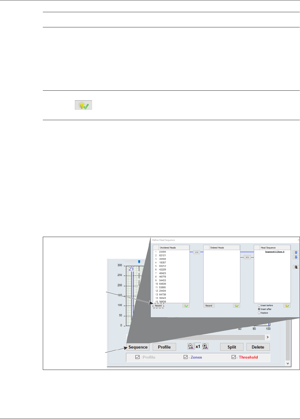
Sequencing the heads
Senstar LM100 Product Guide Page 51
Sequencing can be done by 1 person who starts the recording and then does the location tests, or
by 2 people with 1 monitoring the UCM and the other doing the location tests. To determine the
physical position of each luminaire, and put them into an ordered list, 1 person goes around the
perimeter fence causing a disturbance at each luminaire while the results are recorded on the
UCM. The luminaire AP is the recommended starting point for the sequencing procedure.
However, for your site-specific sensor layout you may prefer to begin at a particular corner or
some other identifiable feature.
Step 1: The Unordered Heads table is populated automatically by selecting the Record button.
The Unordered Heads table includes a numbered list of all luminaires that are communicating on
the wireless mesh network. Each luminaire is identified by a 5-digit mesh network Id. The
Unordered Heads list is based on the luminaires’ RF communication pattern rather than the
installation locations. This process can take several minutes to complete.
Step 2: The Ordered Heads table is completed by conducting location tests to identify specific
luminaires. The luminaires are moved automatically into the Ordered Heads table in the same
order as the location tests are conducted. This enables the luminaires to be organized so that
numerically sequential luminaires can be assigned to segments, regardless of their
communication pattern. The segments are then assigned to zones for alarm reporting and routine
scheduled lighting.
Step 3: The Head Sequence table is completed manually by moving the heads from the Ordered
Heads table. The Heads Sequence table also includes segment and zone number assignments,
once the segments and zones are defined in the segment setting window on the Config tab.
Note Senstar LM100 heads are organized into segments and zones in the
same manner as a FlexZone sensor cable.
Note The Define Head Sequence window includes 3 indicate buttons to
assist in identifying specific luminaires. Select a luminaire from a list,
select the indicate button below the list, and the specified head will flash
5 times.
Figure 48: Define head sequence window (Unordered Heads)
select the Sequence button
select the Record button to
create a list of unordered
(becomes Stop button
to open the Define
while recording)
Head Sequence window
heads

Sequencing the heads
Page 52 Senstar LM100 Product Guide
Compiling the Unordered Heads list
1. Establish a UCM connection to the gateway (USB or TCP/IP).
2. On the Config tab, select the Sequence button.
3. Select the Record button below the Unordered Heads table and wait for the LM100 gateway to
compile the list of unordered heads (this process can take several minutes).
4. Select the Stop button once the compiled list is displayed in the Unordered Heads column.
Verify that all of the installed luminaires have been added to the list to ensure that each
luminaire in the system is communicating properly (e.g., If there are 38 luminaires in your
Senstar LM100 system there should be 38 luminaires in the unordered list.)
If the unordered list is incomplete, repeat this process extending the wait time, before selecting
the stop button. If the list is still incomplete, you must determine which head is not
communicating, and rectify the situation.
5. Proceed to Compiling the Ordered Heads list on page 52.
Compiling the Ordered Heads list
Location testing is done to identify the physical location of each installed luminaire. Each luminaire
is moved from the Unordered Heads list into the Ordered Heads list in the order that the tests are
conducted. To do the location testing, use a screwdriver (or a length of wood like a broomstick) to
strike the shaft of the luminaire (if it is not possible to strike the luminaire’s shaft, strike the fence
post on which the luminaire is mounted). Strike the shaft once firmly, to register the luminaire in the
Ordered Heads list. This will cause the luminaire to flash twice, pause for a second, and then flash
three times to indicate the luminaire has been moved into the Ordered Heads list. In the Ordered
Heads list, the luminaire is identified by a number indicating the test order and by its 5-digit
network Id (see Figure 49: ).
If the luminaire flashes 4 times, this indicates that a second luminaire has also detected the
location test event. In this case, repeat the procedure using less force when striking the shaft.
If the luminaire flashes 5 times, this indicates that the luminaire is already included in the Ordered
Heads table. In this case, proceed to the next luminaire and continue the location testing.
1. Select the Record button below the Ordered Heads table and proceed to the designated first
luminaire (usually the luminaire AP).
2. Strike the shaft of the first luminaire firmly once.
The luminaire will flash twice pause and then flash three times.
The number one and the luminaire’s 5 digit Id are displayed at the top of the Ordered Heads
list.
3. Proceed to the second luminaire and strike the shaft of the second luminaire once.
The luminaire will flash twice pause and then flash three times.
The number two and the luminaire’s 5 digit Id are displayed on the second line of the Ordered
Heads list.
4. Proceed around the perimeter doing a location test at each luminaire, thereby, moving each
luminaire to the Ordered Heads list in the desired sequence.
5. After conducting the test at the final luminaire on the perimeter, return to the UCM computer
and select the Stop button.
6. The Ordered Heads table is now populated by luminaires in the same order that the location
tests were done.
7. Proceed to Compiling the Head Sequence list on page 53.
Tip Use a site plan and mark the number down (from the test order) beside
each luminaire’s location as the tests proceed.
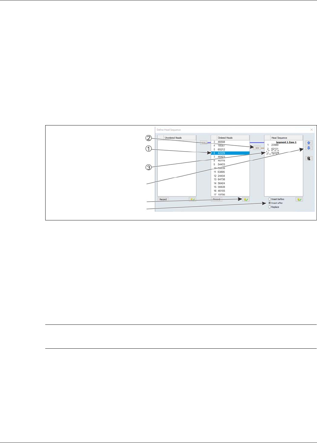
Sequencing the heads
Senstar LM100 Product Guide Page 53
Compiling the Head Sequence list
The Head Sequence list can be compiled one by one, or all of the heads in the Ordered Heads
column can be moved to the Head Sequence table at once. To compile the list one head at a time,
select a head from the Ordered Heads list then select the double arrow beside the Head
Sequence column. To move all of the heads to the Head Sequence table at once, select the first
luminaire in the Ordered Heads list, hold down the shift key and select the last luminaire in the
Ordered Heads list to highlight all of the luminaires. Next, select the double arrow button to move
the Ordered Heads list to the Head Sequence list in the same order.
The Head Sequence list is used to setup segments and zones. To be a part of a segment, the
position numbers of the heads must be sequential. For example, if six heads in the Ordered Heads
list will make up a segment covering the South-West section of fence, then the six heads must be
sequential in the Head Sequence list.
1. Select the first luminaire from the Ordered Heads list and move it to the Heads Sequence
column by selecting the double arrow button.
2. Select the second (sequential) luminaire from the Ordered Heads list and move it to the Head
Sequence column by selecting the double arrow button.
3. Continue this process until all of the heads are moved to the Head Sequence table in the
desired order.
4. If necessary, move the heads around the Head Sequence list by selecting a head and using
the up down arrows to move the selected head’s position in the list.
5. Close the Define Head Sequence window and select the Yes button to save the changes.
6. Save the UCM file and download the configuration changes to the LM100 gateway.
Figure 49: Define Head Sequence window (Head Sequence)
Note Once the segment and zone assignments are made on the Config tab,
the Head Sequence table will include the segment and zone information
with the heads that are assigned to them.
select a head from the Ordered Heads list
select the double arrow button to move the
the highlighted head is moved to the next
(the head will be highlighted in blue)
highlighted head to the Head Sequence list
position in the Head Sequence column
use the up/down arrows to move a head
up or down in the Head Sequence list
use the indicate button to activate a head
use the radio buttons to select the position
in the list for a highlighted head
(the selected head will flash 5 times)
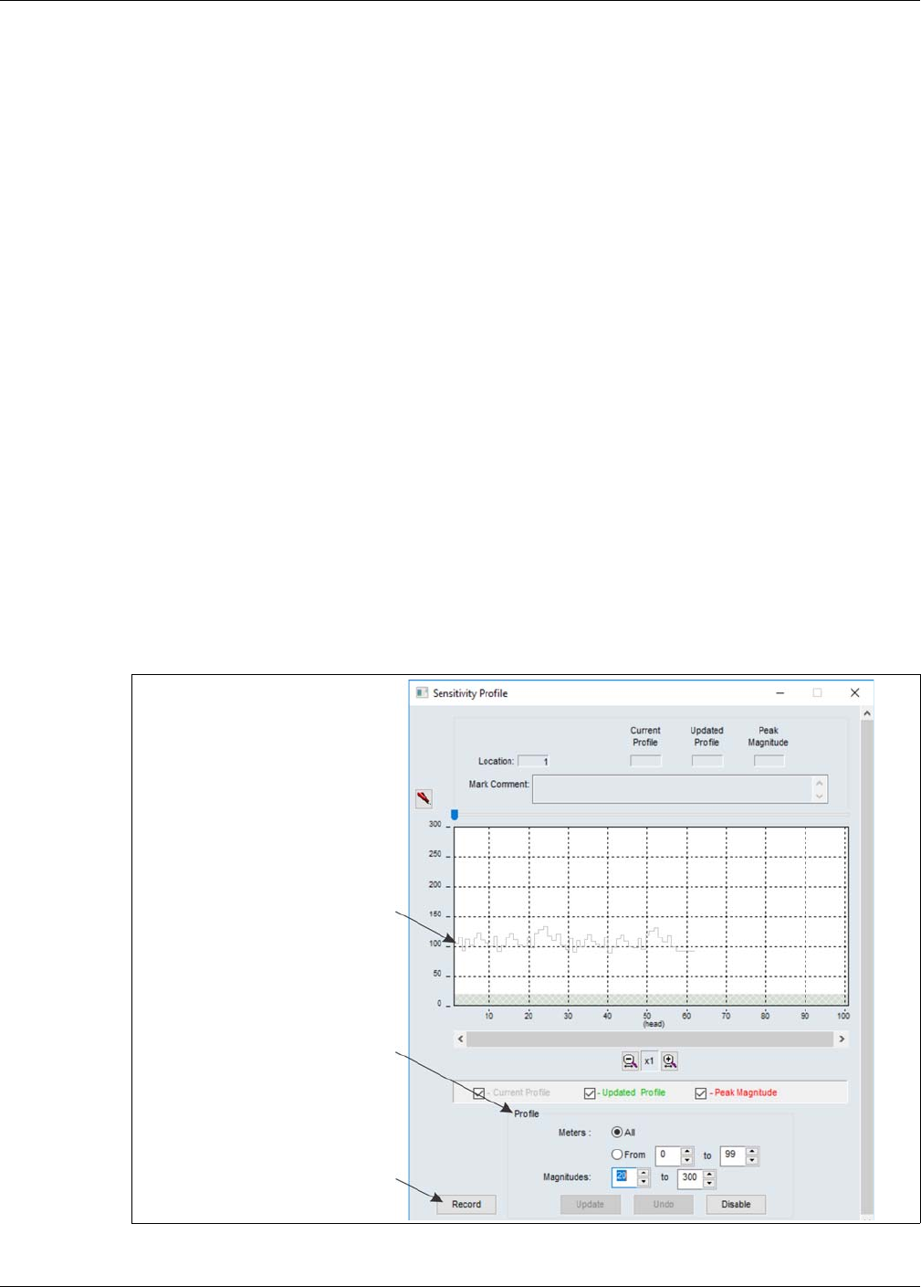
Senstar LM100 calibration
Page 54 Senstar LM100 Product Guide
Senstar LM100 calibration
When calibrating the Senstar LM100 for the first time, begin with the detection parameters in the
default settings.
The Sensitivity Profile
A Sensitivity Profile should be recorded for the full length of the protected fence. The Sensitivity
Profile records each luminaire’s measured response to a consistent fence disturbance. The profile
will verify the luminaire’s detection performance and can identify problems on the fence, or
problems with a luminaire’s attachment.
Recording the Sensitivity Profile
The recommended method for creating the Sensitivity Profile is to drag a screwdriver or similar
instrument along the fence fabric at a consistent height below, the luminaires. Beginning at the
luminaire AP (or the designated first luminaire according to the Head Sequence table) place the
screwdriver against the fence fabric and apply consistent pressure as you walk along the side of
the fence. Keep the pressure steady and maintain a uniform pace as you drag the screwdriver
along the fence fabric. When you reach the first fence post, lift the screwdriver over the post.
Continue dragging the screwdriver along the fence fabric maintaining a consistent distance below
the luminaires and lifting the screwdriver over each fence post until you reach the end of the
protected fence. Keep the pressure of the screwdriver and your walking pace as consistent as
possible. Repeat this process from the end of the protected fence back to the start point.
Figure 50: Sensitivity Profile
raw sensitivity profile data
(gray line)
use the controls in the Profile field
select the Record button to start
recording the profile
(becomes Stop button while recording)
to setup the profile being recorded

Senstar LM100 calibration
Senstar LM100 Product Guide Page 55
1. Establish a connection between the UCM and the gateway.
2. On the Config tab, select the Profile button.
3. Verify that the All radio button is selected, and then select the Record button to begin
recording the Sensitivity Profile.
4. At the luminaire AP, begin dragging the screwdriver along the fence fabric. Lift the screwdriver
over the post at each fence post (i.e., do not strike the fence posts with the screwdriver).
5. Maintain consistent pressure and a steady pace and continue dragging the screwdriver along
the fence fabric at the same level height until reaching the end of the protected fence.
6. Repeat this process, dragging the screwdriver from the end point back to the start point.
7. Select the Stop button to stop recording the Sensitivity Profile.
8. Review the Sensitivity Profile to verify that it was successful.
9. Once you are satisfied with the profile, select the Update button to load the Sensitivity Profile
data. If the recorded Sensitivity Profile is not acceptable, select the Undo button and repeat
the profile procedure.
10. Close the Profile window and download the Sensitivity Profile data to the gateway.
Detection parameter setup
The Senstar LM100 detection parameters are setup globally through the gateway, and are applied
to all of the luminaires. Senstar LM100 detection parameters include the Event Window, the Event
Count and the Alarm Window. The Threshold is set independently for each defined luminaire
segment.
Each LM100 installation includes many site-specific factors. Therefore, the system should be
calibrated to meet the site’s detection requirements:
• Adjust the Threshold to increase or decrease the detection sensitivity of the selected segment.
• Specify the number of Events required to trigger an alarm.
• Specify the period of time that must lapse before a subsequent Event will be recorded at the
same location.
• Specify the period of time in which a subsequent Event must occur.
Note If a sensitivity profile indicates a drop of 50 units within a 10 m length of
the fence, it indicates that there is likely a problem at that location either
with a luminaire or with the fence condition at that location (e.g., loose,
sagging, stretched).
Tip Senstar recommends that you save a UCM file that includes the
recorded sensitivity profile. This can be useful for future maintenance
and troubleshooting activities.
Note The LM100 UCM Config tab includes an indicate button to assist in
identifying specific luminaires. Select a luminaire, or a defined segment,
select the indicate button, and the selected luminaire, or all of the
luminaires in a segment, will flash 5 times.
Senstar LM100 calibration
Page 56 Senstar LM100 Product Guide
Defining the luminaire segments and alarm zones
Each Senstar LM100 system can be organized into up to 50 segments. The defined segments can
then be assigned to as many as 50 distinct alarm zones. Use the UCM software to organize the
luminaires into segments, according to the site’s requirements for alarm detection and response.
The segments are then assigned to zones to fit the alarm zone layouts for display and control, and
routine lighting. Once the segments and zones are setup, you adjust the Threshold independently
for each defined segment to match the sensors response to the fence conditions and to increase
or decrease the detection sensitivity for that segment.
Figure 51: LM100 Config tab
Note Luminaires must be numbered sequentially in the Head Sequence list
to be assigned together in a segment (e.g., heads 4, 5, 6, 7 could be
assigned to a segment, but heads 4, 5, 6, 9 could not).
Note Any luminaires that are used only for lighting purposes (e.g., to light a
walkway or entrance) should be assigned to a segment in which the
threshold is set to maximum. This enables routine scheduled lighting
control and disables alarm detection.
Event Window setting
Event Count setting
Alarm Window setting
Threshold adjustment arrows
recorded Profile (gray line)
Threshold set slightly below profile (red line)
(period that must lapse before a subsequent
Event is added to the Event count)
(number of Events that will cause an alarm)
(period in which a
Target Filter
Comm Channel
Normal Light Control (brightness)
Auto Light Control
(alarm response)
Segment definition and control settings
(setup segments, zones and alarm relays)
Sequence button (setup head sequence)
Profile button (record Sensitivity Profile)
Split button (divide selected Segment)
Delete button (delete selected Segment)
subsequent Event must occur)
(use to adjust all thresholds simultaneously)
Segment setting window
Senstar LM100 calibration
Senstar LM100 Product Guide Page 57
Defining the initial zone
When the sequencing procedure is completed, the segment setting window on the Config tab will
have one segment which is assigned to zone 1 (see Figure 51: ).
Defining the segments
The first segment, Segment 1, Zone 1 includes Head: 1 to 100 (even if the system does not
include 100 luminaires). Select the Split button and there will be 2 segments, with both assigned to
Zone 1. Segment 1 includes luminaires 1 - 50 and Segment 2 includes luminaires 51 - 100. (Each
time you select the split button, you divide the selected segment into two equal sections.) Next,
specify the luminaire that will be the start point of the second segment. (e.g., If the first segment
will include luminaires 1 to 7, then the second segment will start with luminaire 8.) Next, assign the
defined segment a zone number for alarm reporting and lighting control. Each LM100 can include
up to 50 segments and up to 50 distinct alarm zones.
1. Below the segment setting window, select the Split button.
The selected segment is divided into 2 sections, the white section is the currently selected
segment.
2. Left-click the boundary line and drag the zone boundary to the appropriate point in the
segment setting window (or use the Head: field spin control to enter the number of the
luminaire that represents the start of the currently selected segment).
3. Use the Zone: spin control to assign the segment to an alarm zone (label the zone according
to the site plan; multiple segments can be assigned to one zone).
4. Repeat this procedure to define each luminaire segment and zone, as specified in the site
plan.
5. Save the UCM file and download the configuration data to the gateway.
Note You can use the horizontal magnification button to provide a closer
view.
Figure 52: Defining luminaire segments
magnification buttons
use the Delete button to merge the selected
segment with the preceding segment
segment assigned to Zone 5 has threshold set
the assigned Zone label is centered at the top
of the segment
to maximum (255) to enable scheduled light
control and disable alarm detection
Senstar LM100 calibration
Page 58 Senstar LM100 Product Guide
Verifying the luminaire segment boundaries
1. Establish a UCM connection to the LM100 gateway and select the Config tab.
2. Select File > Response Plot and set the Senstar LM100 response plot so the Display Format is
Magnitude vs Location, the Heads: All radio button is selected, and the Peak Capture
checkbox is selected.
3. Select the Record button to start the plot.
4. Have the tester tap the fence post of the luminaire that is defined as the start point of the
second segment with the blade of a screwdriver (or similar object). Use consistent force and
tap 3 times waiting 2 seconds between each tap.
5. On the UCM, verify that the alarm was reported by the luminaire defined as the second
segment’s start boundary.
6. Move along and continue tapping fence posts to mark the start points of the designated
segment boundaries.
Setting the Threshold
The Threshold represents the received signal strength at which the Event Count is incremented.
An independent Threshold can be set for each of the defined segments. Thresholds can be
adjusted for any high risk or low threat areas, as well as any areas that may be subject to a higher
NAR such as an open stretch of fence that is regularly exposed to strong winds. The Threshold
can also be used to disable alarm detection in a segment by setting the Threshold to the maximum
value of 255. Reducing the Threshold in high risk areas will increase the Pd in that area. However,
a lower Threshold setting may increase the nuisance alarm rate. For an area where the threat is
considered low, increasing the Threshold will reduce the chance of nuisance alarms occurring
while still providing an acceptable Pd.
Note Senstar recommends marking a site plan (or a table) with numbered
luminaire locations, the segments to which the luminaires are assigned
and the alarm zones to which the luminaire segments are assigned.
The initial segment begins with luminaire 1 (by default).
Note You can use the indicate button to identify boundary locations by
activating the head that represents the boundary.
Figure 53: Segment and zone assignments on the Head Sequence window
Senstar LM100 calibration
Senstar LM100 Product Guide Page 59
The Threshold is usually set with respect to the recorded Sensitivity Profile. Select a segment,
then use the Threshold: spin controls to set the Threshold for that segment. A good starting point
is to set the Threshold just below the recorded Sensitivity Profile in each segment. You can use the
up down arrows beside the segment setting window to lower, or raise the Threshold for all defined
segments.
Segment threshold setting procedure
1. Establish a UCM connection to the gateway and select the Config tab.
2. Select a segment then use the Threshold: spin controls to set the Threshold for that segment.
3. Repeat for each defined segment.
4. Use the Threshold adjustment arrows to adjust the Threshold for all installed luminaires, if
desired.
5. Save the UCM file and download the configuration data to the gateway.
Figure 54: illustrates a Segment setting window for an LM100 system, which has been split into 6
segments and 5 zones. Segments 1, 2, 4 and 5 (Zones 1, 2 and 4) use the same Threshold
setting. Segment 4 (Zone 3) is considered a high threat area and the Threshold has been set to a
lower value to increase the detection sensitivity in that zone. Segment 3 represents a group of
luminaires that are used exclusively for lighting purposes (no alarm detection required) so the
segment Threshold is set to the maximum value of 255.
Note Left-clicking in the Segment window and using the up and down arrows
on the keyboard, or the mouse wheel will also adjust the Threshold.
Note Set the Threshold after the Sensitivity Profile is completed and
downloaded to the gateway.
Note Intrusion testing is used to verify the Threshold settings.
Figure 54: Setting the segment Thresholds
Threshold
lower Threshold setting
for high security Zone 3
Threshold set for scheduled light
control without alarm detection
(segment Threshold set to 255)

Senstar LM100 calibration
Page 60 Senstar LM100 Product Guide
Intrusion simulations
Conduct simulations for both cut and climb intrusions to test the Senstar LM100 system. The
easiest method for simulating a cut intrusion is to firmly tap the fence with the blade of a medium
sized screwdriver. Hold the screwdriver by the handle, and flip your wrist to bring the blade into
contact with the fence. The metal on metal contact generates an impulse that is similar to the
cutting of a fence wire.
Weaving a length of fence wire into the fence fabric and then cutting the inserted wire can also
simulate a cut intrusion. Both methods generate a signal that is similar to the response of an actual
cut intrusion. An actual fence cut also creates a significant amount of secondary fence noise as
the cut section of wire pulls apart.
For a simulated climb intrusion, the best method is to actually climb the fence. It is not necessary
to climb over the fence. The tester simply needs to climb on the fence for a period that exceeds the
Event Window time setting X the Event Count setting (e.g., 1 second X 3 Events = 3 seconds). If
climbing on the fence is not possible, dragging a screwdriver across the surface of the fence can
be used as a climb simulation. Place the blade of a screwdriver against the fence fabric and drag
the screwdriver back and forth across the fence panel while applying light pressure. Continue this
for the Event Window time setting X the Event Count setting.
Start a UCM magnitude response plot and then thoroughly test the detection along the full length
of the protected fence, while running the plot. Adjust the detection parameters if any of the test
intrusions fails to report an alarm simulation. Next, run a long term UCM magnitude response plot
to monitor the system for nuisance alarms, especially during periods of inclement weather. Adjust
the detection parameters if bad weather causes an unacceptable nuisance alarm rate. Once the
system is detecting all intrusion simulations and the NAR is at an acceptable rate, the system is
properly calibrated for the site. Save a UCM file that includes the gateway’s current settings.
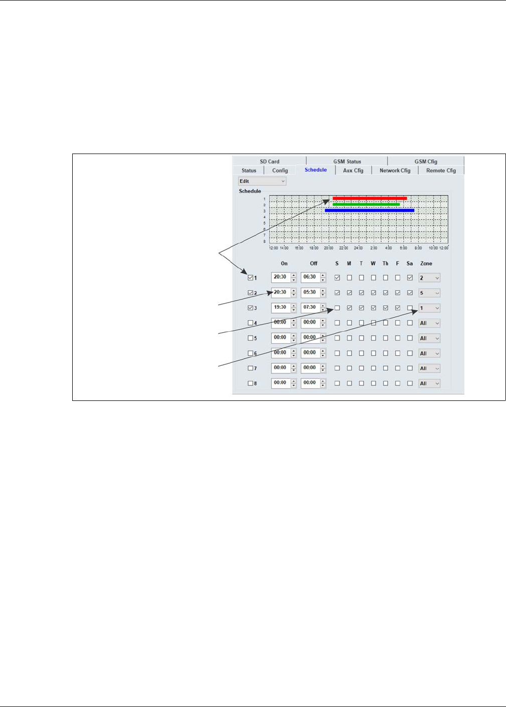
Scheduling routine light activation
Senstar LM100 Product Guide Page 61
Scheduling routine light activation
Once the segment and zone assignments are made, a schedule can be setup for routine light
activation. The Senstar LM100 enables up to 8 independently scheduled light activations for
defined luminaire zones. Set the light level (brightness) for normal light control on the Config tab.
Specify the time at which the lights turn on, the time at which the lights turn off, the days of the
week on which the activations occur, and the zone to which the schedule applies, on the Schedule
tab.
Scheduling routine luminaire activation
1. On the Config tab, use the slider in the Normal Light Control section to set the brightness of
the luminaires that will be activated by the schedule.
2. Select the Schedule tab and select (check) the first scheduling checkbox.
3. Set the time at which the luminaire(s) will turn ON.
4. Set the time at which the luminaire(s) will turn OFF.
5. Choose the days of the week that the activation will occur.
6. Choose the luminaire zone that will activate according to the schedule.
7. Save the UCM file and download the configuration changes to the LM100 gateway.
Figure 55: Setting individual segment Thresholds
select a checkbox to setup a
set the time at which the lights
routine lighting schedule
turn On and Off
select the days of the week
specify the zone to activate
(select All to activate all
installed luminaires)
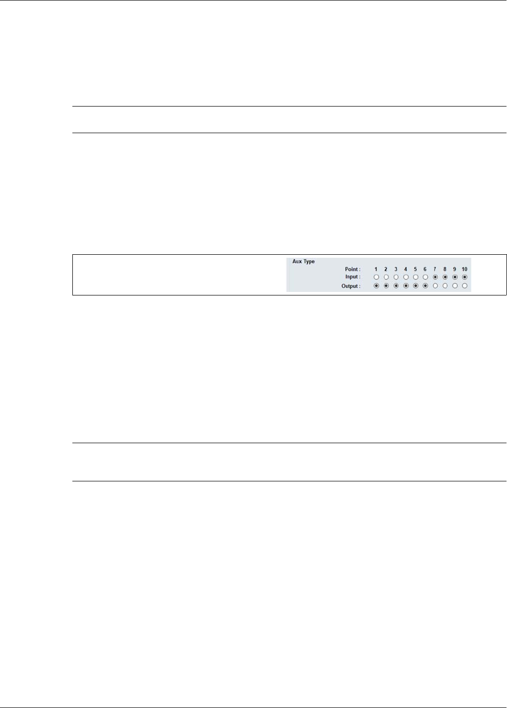
Input/output configuration
Page 62 Senstar LM100 Product Guide
Input/output configuration
This section details the procedures for configuring the gateway’s inputs and outputs (I/O) for Local
control and Remote control operation.
Specifying the Auxiliary I/O control mode, I/O type and option card
1. On the Aux Cfig tab select the Arrow beside the Aux Control: field.
2. Specify the control mode for this gateway (Local or Remote).
3. If the gateway includes an option card, specify the type (Input or Output).
4. Use the 10 Aux Type radio buttons to set each I/O point as either an input or an output.
5. Save the UCM configuration file and download the configuration changes to the gateway.
Auxiliary (Aux) inputs
The I/O points specified as inputs on the gateway are voltage sensing inputs. The gateway
determines an input’s status via an internal reference voltage, and the configuration of the contact
closures and supervision resistors. Input contact closures MUST be voltage-free. Define the inputs
as normally open (NO) or normally closed (NC) with single resistor supervision, dual resistor
supervision, or unsupervised. The Filter Window parameter enables the setting of the time period
for which an input must be active, before the gateway reports an event.
Local control mode
In local control mode, the Aux inputs are used to activate luminaire zones in response to the inputs
of auxiliary security equipment. Select the input, specify the input’s parameters, and then specify
which luminaire zone will be activated when the input is activated.
Remote control mode
In Remote control mode, the Aux inputs serve as auxiliary device inputs to the host Security
Management System (SMS). The inputs are available for reporting the status of other security
devices. The gateway reports any change of an input’s state to the SMS via the Silver Network
Manager.
Note See document # 00DA1003-002 for details on using the UltraLink
modular I/O system to report Senstar LM100 alarm conditions.
Figure 56: Aux Type settings
Note The four inputs on the (dry contact input card) DRIC function the same
as the inputs on the gateway. Follow the directions for setting up the
gateway’s AUX inputs to setup the inputs on the DRIC (if applicable).
use the radio buttons to specify each port’s function
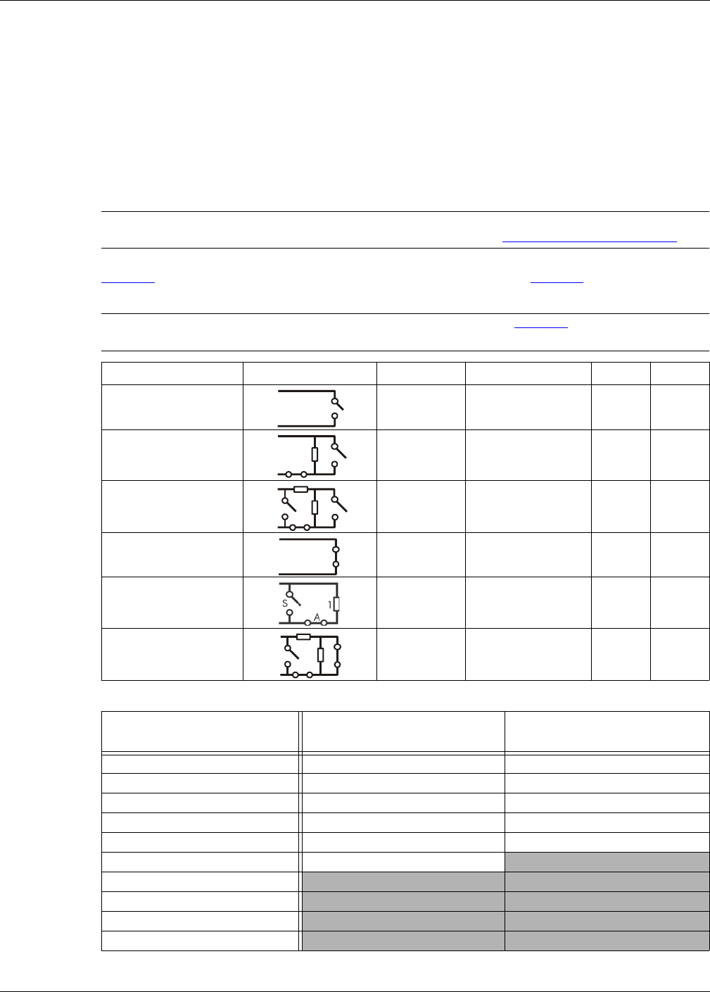
Input/output configuration
Senstar LM100 Product Guide Page 63
Remote light activation
In both local control mode and remote control mode, the LM100 can be configured to have specific
luminaires activated from remote locations. In local control mode, a simple on/off switch in a
central control room can be connected to an Aux input on the gateway. When the switch is turned
on the aux input goes high and the luminaire zone that is specified to activate in response turns on
(Zone Light Activate on the Aux Config tab). In remote control mode a command from the host
SMS can activate a luminaire zone.
Input wiring configurations
Table 2: includes the selectable Aux input wiring configurations, and Table 3: includes the
selectable supervision resistor values.
CAUTION The I/O port configuration jumpers must be correctly set according to
the specific function of each port (see I/O port jumpers on page 32).
Note Use ¼ W 1% supervision resistors (see Table 3: for recommended
resistor values).
Input option UCM selection Alarm relay Supervision R1 R2
unsupervised NO --- --- ---
single resistor
supervision NO cut 5.1 k ---
dual resistor
supervision NO cut & short 4.3 k 820
unsupervised NC --- --- ---
single resistor
supervision NC short 5.1 k ---
dual resistor
supervision NC cut & short 5.1 k 820
Table 2: Selectable input configurations
R1 values (single resistor
supervision)
R1 values (double resistor
supervision)
R2 values (double resistor
supervision)
820 1.1 k 820
1 k 2.2 k 1.1 k
1.1 k 4.3 k 2.2 k
1.2 k 4.7 k 3.3 k
1.5 k 5.1 k 5.6 k
2.2 k 5.6 k
3.3 k
4.7 k
5.1 k
5.6 k
Table 3: Selectable resistor values
A
1A
S
1
2A
S
A
1
2A
S

Input/output configuration
Page 64 Senstar LM100 Product Guide
Input configuration procedure
1. Select the Aux Cfig tab on the UCM window.
2. From the Supervision drop down, select the desired supervision scheme for the input.
3. Select the Resistor 1 value, if applicable.
4. Select the Resistor 2 value, if applicable.
5. Set the Noise Tolerance, if required.
6. Set the Line Drop, if required.
7. Set the Filter Window.
8. For Local Control mode, specify the luminaire zone to activate when the input is activated.
9. Repeat this procedure for each input.
10. Save the UCM configuration file and download the configuration changes to the gateway.
Output relays
Output relay setup (Local control mode)
In Local control mode, the Aux outputs are setup via the Local Aux Control Activation check boxes
to report alarm and supervision conditions. The outputs are then controlled by the gateway to
activate on the user-specified conditions. The outputs remain active for an event’s duration or for
the selectable relay Active Time, whichever is longer.
1. Use the Output selection arrows to select a relay.
2. Select the relay’s function: high side drive power sourcing; Form A (N.O.) or Form B (N.C.)
power sinking (up to 100 mA power sourcing/sinking); or dry contact Form A or Form B.
3. Specify the Hold/Active Time parameter.
4. Specify the conditions from the Local Aux Control Activation field under which this relay will
activate. Zone alarms are assigned on the segment setting window on the Config tab.
5. Repeat this procedure for each defined output.
6. Save the UCM configuration file and download the configuration changes to the gateway.
Output relay setup (Remote control mode)
In Remote control mode, the relays are controlled by the host SMS to operate auxiliary equipment
as output control points (e.g., to activate lights, doors, sirens, CCTV equipment, etc.). The relays
are configured to respond to commands from the host computer. Configure the relays as latching
(ON by command, OFF by command) or in flash mode (ON-OFF-ON-OFF etc. by command, OFF
by command) or in pulse mode (ON for a period, then OFF). For flash and pulse modes, the ON-
OFF time duration is configurable.
CAUTION The I/O port configuration jumpers must be correctly set according to
the specific function of each port (see I/O port jumpers on page 32).
Note The four outputs on the ROC are Form C (selectable as N.O. or N.C.).
The ROC outputs cannot source or sink power.
Note To use the onboard relays, the gateway ports must be configured as
outputs via the Aux Type radio buttons.
Note To assign relays to specific zones, see Linking segments to relays (local
control mode) on page 65.
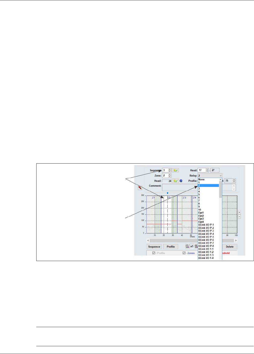
System test procedure
Senstar LM100 Product Guide Page 65
1. Use the Output selection arrows to select a relay.
2. Select the relay’s function: high side drive power sourcing; Form A (N.O.) or Form B (N.C.)
power sinking (up to 100 mA power sourcing/sinking); or dry contact Form A or Form B.
3. Select the type of relay Activation (latching, or flash mode, or pulse mode).
4. Select the Hold/Active Time parameter, if applicable.
5. Select the Inactive Time parameter, if applicable.
6. Repeat this procedure for each defined output.
7. Save the UCM configuration file and download the configuration changes to the gateway.
Linking segments to relays (local control mode)
The gateway’s outputs and the four relays on the ROC (OPT 1, OPT 2, OPT 3, OPT 4) can be
linked to the defined luminaire segments. This provides up to 14 relays per gateway, for signaling
alarm conditions.
1. Under the Config tab, on the Segment Settings window, select the segment to which a relay
will be associated.
2. From the pull down menu, select the relay which will be associated with the segment (the
selected relay activates to signal an alarm in the luminaire segment).
3. Repeat steps 1 and 2 until the defined segments have associated relays, as required.
4. Save the UCM configuration file and download the configuration changes to the gateway.
System test procedure
Once the system is setup and calibrated, conduct a series of tests to verify detection. Run a UCM
Response plot during the testing. Network based gateways can be tested over the network to
verify network communications.
Figure 57: Linking relays to segments
Note The following tests can be used to verify gateway system operation.
The tests are described in a generic manner, which does not take into
account site specific details.
select the segment to which a relay
will be assigned
select the relay from the drop down menu

System test procedure
Page 66 Senstar LM100 Product Guide
•Cut detection - Use the tap test, or weave a piece of scrap fence wire into the fabric of the
fence and cut the scrap wire. Test each zone in at least three separate locations.
At each location, tap the fence fabric, or cut the scrap wire, the number of times specified by
the Event Count parameter + 1. Wait at least 2 seconds between taps.
PASS ____ FAIL____
•Climb detection - Have a tester climb on the fence fabric for at least as long as it would take
to climb over the fence (or use the screwdriver drag method). Repeat the climb simulation in at
least three locations per zone.
PASS ____ FAIL____
•Fence lift detection (This test may not be possible on a number of fence types. Use care to
ensure that the fence is not damaged during this test) - Have a tester lift or pry up the bottom
the fence fabric for a minimum of the Event Time X the Event Count (depending on the amount
of fence noise being generated, the test may have to exceed the Event Time setting by several
seconds). Repeat the lift test in at least three locations per zone.
PASS ____ FAIL____
•Enclosure tamper - Open the gateway’s enclosure. The DOOR OPEN LED (D1) turns ON,
and the UCM Enclosure Tamper indicator turns ON, and the Event log reports an Enclosure
Tamper alarm. If a relay is configured to activate for an enclosure tamper, the designated relay
activates.
PASS ____ FAIL____
•Auxiliary inputs - For Local control mode the Aux inputs activate luminaire zones. In this
case, activate the input, and verify that the specified luminaire zone activates in response.
For Remote control mode, the Aux inputs serve as auxiliary device inputs to the host Security
Management System. In this case, activate the connected device, and verify the status
change is reported by the host SMS. Repeat for each configured input.
PASS ____ FAIL____
•Relay outputs - For Local control mode the relay outputs are used to report events. Cause an
event, and verify that the configured relay activates for a minimum of the relay hold time. Verify
that the connected device activates. Repeat this procedure for each specified event.
For Remote control mode, the relays serve as output control points for the host SMS. Send an
activation command from the host SMS to a relay and verify that the relay activates. Verify that
the connected device activates. Repeat this procedure for each relay.
PASS ____ FAIL____
•Normal Light Control - If a schedule has been setup to activate luminaire zones at specific
times on specified days, verify that the luminaire zones activate and deactivate according to
the schedule.
PASS ____ FAIL____
•Auto Light Control - For luminaire zones that are setup to activate in response to alarm
conditions, simulate an alarm and verify that the luminaire zone activates as specified.
PASS ____ FAIL____

Senstar LM100 Product Guide Page 67
4 Maintenance
Recommended maintenance
The Senstar LM100 system requires minimal maintenance to ensure proper operation. However,
setting up and following a maintenance schedule based on your site-specific requirements can
ensure proper detection performance, prevent nuisance alarms and extend the operational lifetime
of the system. The frequency at which the maintenance should be scheduled depends on the
site’s security requirements and on the installation environment. This section includes the
recommended maintenance activities along with suggested intervals.
1. Perform a visual inspection of the installation (once per month). Check for the following:
• fence condition - ensure the fence is in good condition and that there are no loose panels,
loose fittings or metal bits that can move with the wind and cause nuisance alarms (a
shake test in which you grip the fence fabric in the middle of a panel and gently shake it
with an increasing motion can help identify any loose pieces)
• there are no washouts or depressions under the fence
• vegetation beside and above the fence is cut back and cannot make contact with the
fence or the luminaires, and there is no debris or loose material close to the fence
• there are no loose clamps; each luminaire is held tightly against the fence post
• power cables are neatly installed and are held securely by the cable ties
• there is no corrosion or moisture inside the gateway enclosure
• the ground connection is tight
• there are no vehicles or equipment close enough to the fence to be used as bridging aids
2. Physically test the system (once per week).
• use a screwdriver to simulate a series of cut intrusions and verify that alarms are declared
and accurately located each time
• climb the fence at several locations and verify that alarms are declared and accurately
located each time
3. Record a UCM LM100 response plot (quarterly).
Connect the UCM to the gateway and record a sensor response plot while conducting tap
tests along the protected fence. Note the environmental conditions at the time of the recording.
Review the plot to examine the response and the ambient noise level, and compare the plot to
any previously recorded plots. Depending on the weather conditions, the recorded plots
should be quite similar. During inclement weather the noise level will be higher, and during
good weather with very little wind, the noise level should be extremely low.
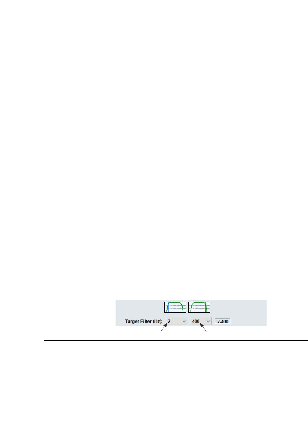
Recommended maintenance
Page 68 Senstar LM100 Product Guide
4. Snow removal (as required)
If the weather conditions at your site include snow falls, the fence should be kept clear of
accumulating snow. If snow accumulates against and around the fence, it will absorb and
dampen the vibrations caused by an intrusion attempt. In addition, if there is significant snow
accumulation, the snow can serve as a bridging aid to defeat the system.
Preventing weather related nuisance alarms
If your Senstar LM100 system is having a problem with nuisance alarms during inclement weather,
connect the UCM to the gateway and review the alarm history to try to determine the source of the
nuisance alarms. Investigate the areas near the luminaire(s) with the highest alarm count. Inspect
the fence to ensure it is in good condition and there are no loose fittings that can cause metal on
metal contact. Check the attachment and test the detection of any luminaire(s) with a higher than
average nuisance alarm rate.
For network based systems, run a UCM response plot through the Network Manager during
periods of inclement weather. If the weather causes an unacceptable number of nuisance alarms,
review the plot and the processor history and adjust the Threshold to mitigate the effects of the
weather. For standalone systems that encounter an unacceptable number of nuisance alarms
during inclement weather, connect the UCM to the gateway, review the processor history and
adjust the Threshold to mitigate the effects of the weather.
To determine if there are any loose fittings or parts of the fence that can cause nuisance alarms in
windy weather, grip a fence panel in the middle and push and pull on the fence with an increasing
motion. Run a response plot to record the shake tests, and listen for any metal on metal contact.
Review the plot, looking for any response spikes that are over the threshold. If the shake test
causes metal on metal contact, or generates response spikes over the threshold, locate and
correct the problems on the fence. This will help to prevent weather related nuisance alarms.
Adjusting the Target Filters
The gateway includes both a high pass and a low pass filter which can be used to screen out some
sources of nuisance alarms. Before adjusting the Target Filters, verify that the fence is not loose
and that there are no objects or vegetation that may be contacting the fence in strong winds. The
default value for the high pass filter is 2 Hz, the default value for the low pass filter is 400 Hz.
• If the site is encountering an unacceptably high NAR during moderate to strong winds,
increase the high pass filter setting slightly to lessen the effects of wind sway and continue
monitoring for nuisance alarms.
• If the site is encountering detection problems (low sensitivity) rather than nuisance alarms, the
most likely source of the problem is loose fence conditions. Repeat the profiling procedure and
compare it to the original sensitivity profile. Once the location of the low sensitivity has been
determined, correct the problem by repairing the damaged section of fence.
If the fence has been restored to the fullest extent possible and the sensitivity problems
persist, it may be necessary to install additional luminaires in this area.
Note After adjusting the Threshold, retest the system to ensure that the
detection meets the site’s security requirements.
Figure 58: Target Filters
high pass filter low pass filter

Replacing the gateway
Senstar LM100 Product Guide Page 69
Replacing the gateway
The gateway PCB is mounted inside the enclosure on four standoffs.
Removing the gateway assembly
1. Label and disconnect the removable terminal blocks.
2. Disconnect the tamper switch connector from the gateway.
3. If required, remove the network interface card.
4. Remove and retain the mounting hardware from the gateway CCA (2 standoffs, 2 machine
screws + washers) (see Figure 28: ).
5. Lift the gateway CCA out of the enclosure. Place the CCA into an anti-static bag.
Replacing the gateway assembly
1. Fit the replacement gateway inside the enclosure so the 4 mounting holes are lined up with the
standoffs.
2. Use the retained mounting hardware to secure the CCA to the enclosure.
3. If required, replace the network interface card.
4. Reconnect the tamper switch connector.
5. Reinstall the removable terminal blocks.
6. Apply power to the gateway, connect the UCM and download the replaced gateway’s
configuration file to the replacement gateway.
7. Retest the protected fence.
Updating the Senstar LM100 Firmware
To update the Senstar LM100 device firmware (gateway, luminaire, wireless gate sensor) select
the Application button in the Program field at the top of the UCM screen. The following example
will illustrate updating the luminaire firmware, which can take up to 30 minutes to complete due to
the distributed locations of the luminaires, and the low power RF transmissions. Begin by obtaining
the firmware upgrade from Senstar Technical Services. Save the firmware file to a known location
(e.g., a folder on your desktop). Save a UCM file with your current settings as a safety backup
before proceeding with the update.
1. Select the Application button in the Program field at the top of the UCM screen.
Note Always reprofile and retest the fence if the Target Filters are adjusted or
fence repairs are made
CAUTION The gateway and the NIC include static sensitive components. Follow
proper ESD handling procedures when working on the electronics.
Place both circuit card assemblies (CCA) into anti-static bags once
they are removed from the enclosure.
Disconnect all power sources before removing the gateway from the
enclosure.
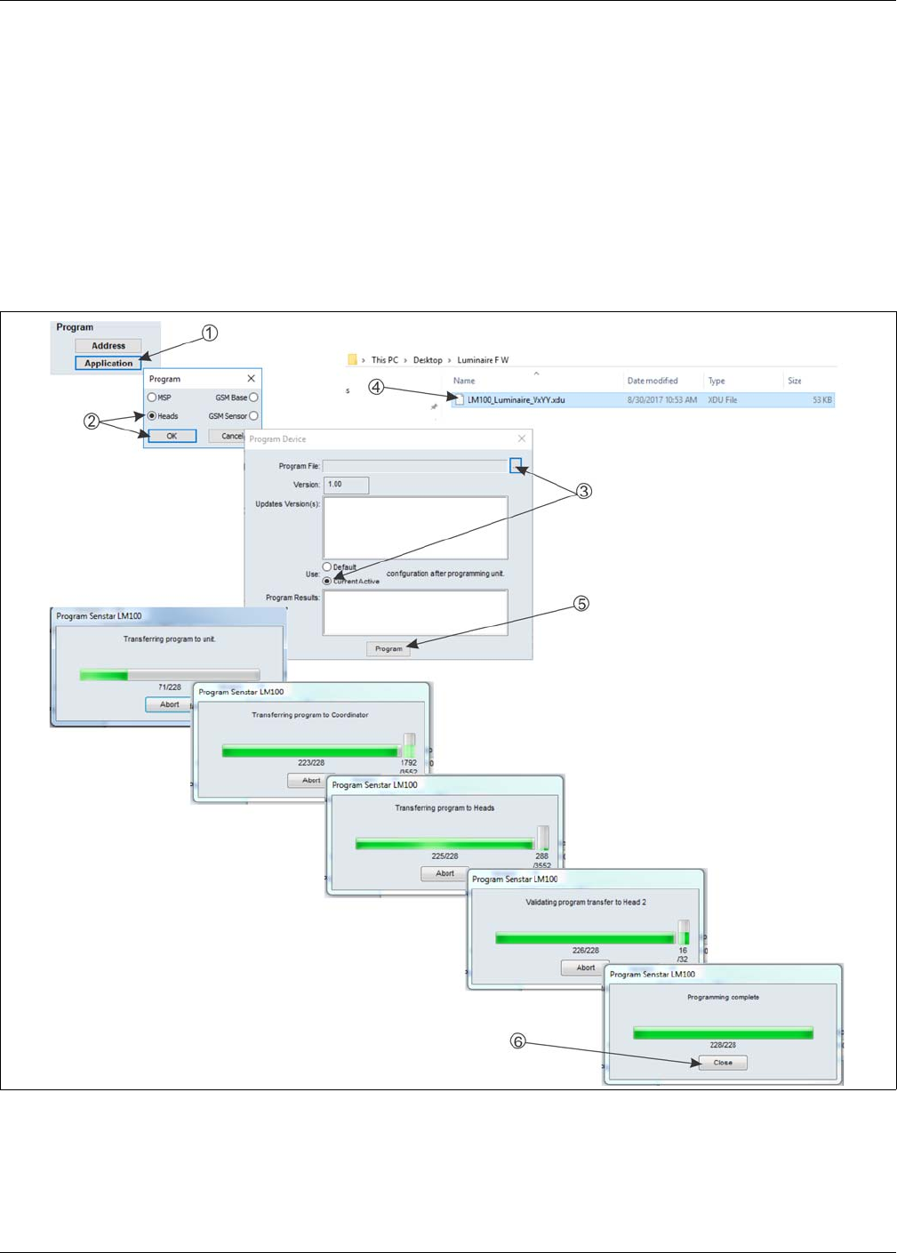
Updating the Senstar LM100 Firmware
Page 70 Senstar LM100 Product Guide
2. Specify the device firmware being updated and select OK (i.e., MSP for gateway, Heads for
luminaires, GSM Base for wireless gate sensor receiver, GSM Sensor for gate sensor
module).
3. Select the Use: Current Active configuration after programming unit radio button, then select
the Browse button.
4. Navigate to the location of the firmware file and select the appropriate .XDU file.
If you select an incorrect .XDU file, the UCM will not allow the installation.
5. Select the Program button on the Program Device dialog.
A series of progress windows will be displayed as the firmware is loaded into the devices.
6. When the programming Complete window is displayed, select OK.
7. Reset or restart the gateway.
Figure 59: Target Filters
high pass filter low pass filter

Senstar LM100 Product Guide Page 71
aParts list
Component Part Number Description
Senstar LM100
Senstar LM100 gateway and
enclosure
E8EM0300 gateway mounted in an outdoor rated painted aluminum enclosure,
provides electronic processing for up to 100 luminaires on up to 600
m (1970 ft.) of fence
Senstar LM100 gateway and
luminaire AP
E8FG0300 gateway in enclosure with luminaire AP and documentation CD
Senstar LM100 gateway E8BA0200 gateway circuit card (spare with no enclosure)
Senstar LM100 luminaires
Senstar LM100 luminaire AP E8FG0110 luminaire AP with 3 m (10 ft.) RS-485 comm/power cable for hard-
wired connection to gateway (1 required per Senstar LM100 system)
Senstar LM100 luminaire E8FG0210 1 luminaire with post clamps, power cable crimps and grommet
Senstar LM100 luminaire E8FG0250 5 luminaires with post clamps, power cable crimps and grommets
Senstar LM100 luminaire E8FG0220 20 luminaires with post clamps, power cable crimps and grommets
Senstar LM100 accessories
UV resistant cable ties GH0916 UV resistant polypropylene cable ties for power cable installation,
1000 piece bag
stainless steel clamps GH1080 stainless steel post clamps for post mounting gateway/luminaire (fits
4.5 to 12.7 cm; 1¾ to 5 in. OD post size)
power cable (14/2) GW0337-14 152 m (500 ft.) reel of 14 AWG, 2 conductor, outdoor rated, low
voltage power cable
power cable (16/2) GW0337-16 152 m (500 ft.) reel of 16 AWG, 2 conductor, outdoor rated, low
voltage power cable
power cable crimps GX0310 manual installation tool for stainless steel cable ties
luminaire grommet GH1095 grommet used to secure the power cable inside the base of the
luminaire
Molex crimp tool G6KT0300 recommended crimp tool for power cable crimps
Klein crimp tool G6KT0300 suitable crimp tool for power cable crimps
input card 00BA2400 plug-in option card provides 4 dry contact (voltage sensing) inputs

Page 72 Senstar LM100 Product Guide
output card 00BA2500 plug-in option card provides 4 relay outputs
Gate accessories
wireless gate sensor module
(GSM)
E7EM0201 battery powered wireless gate sensor module mounts on gate and
communicates via RF with plug-in module on the gateway
wireless gate sensor module
(GSM)
E7EM0202 solar powered wireless gate sensor module mounts on gate and
communicates via RF with plug-in module on the gateway
gate sensor receiver card for
WGS
E7FG0301 plug-in module for SenstarLM100gateway, communicates via RF
with GSM
Network accessories
Silver Network Interface Unit 00EM0200 Silver Network data converter for RS-422 and multi-mode fiber optic
applications
Silver Network Interface Unit 00EM0201 Silver Network data converter for RS-422 and single-mode fiber
optic applications
Mini Silver Network Interface
Unit
00EM1301 Silver Network data converter for USB to RS-422 and multi-mode
fiber optic applications DIN rail mount
Mini Silver Network Interface
Unit
00EM1302 Silver Network data converter for USB to RS-422 and single-mode
fiber optic applications DIN rail mount
Data converter GB0360-ST Ethernet to dual RS-422 data converter (0 to 60º C operating temp)
Data converter GB0360-ET Ethernet to dual RS-422 data converter (-40 to +75º C operating
temp)
Data converter mounting kit GB0360-MK 35 mm DIN rail mounting kit for Ethernet to dual RS-422 data
converters
Network Interface Card
(multi-mode fiber)
00BA1901 Network interface card for multi-mode fiber optic communications
Network Interface Card (RS-
422)
00BA2000 Network interface card for copper wire communications
Network Interface Card
(single-mode fiber)
00BA2101 Network interface card for single-mode fiber optic communications
Network Interface Card
(Ethernet PoE)
00BA2200 Power over Ethernet network interface card for Ethernet
communications
UCM software
UCM cable GE0444 UCM interface cable, 3 m, USB (connects PC running UCM to
gateway)
UCM 00SW0100 Universal Configuration Module software, Windows-based
application, setup, calibration and diagnostic tool
UltraLink CD
Network Manager service
software
00FG0220 Network Manager service software CD for Silver Network plus Alarm
Integration Module software (requires hardware key for operation)
AIM hardware key 00SW0230 USB security dongle for AIM software operation
Component Part Number Description

Senstar LM100 Product Guide Page 73
b Specifications
gateway
Model • gateway circuit card and enclosure
PCB dimensions (L x W) • 13.2 x 14.5 cm (5.2 x 5.7 in.)
Quantity • one gateway per Senstar LM100 system
Enclosure • IP66/NEMA 4 painted aluminum, outdoor rated
• L x W x D
26 cm (+2.5 for cable glands) x 16 cm x 9 cm
10.25 in. (+1 for cable glands) x 6.3 in. x 3.5 in.
• 4 holes for flat surface mounting, use 7 mm (¼ in.) hardware
Cable entry ports • 4 small cable ports (17 mm, 0.67 in.) fitted with 9.5 mm (3/8 in.)
compression glands: cable range: 2.9 - 7.9 mm (0.115 to 0.312 in.)
• 1 large cable port (22.2 mm, 0.875 in.) fitted with compression gland:
cable range: 4.3 - 11.4 mm (0.17 to 0.45 in.)
Probability of detection • 95% with a 95% confidence factor for cutting the fence, lifting the fence
fabric, or climbing over the fence unaided (based on a high quality
chain link fence, and following manufacturers’ installation and
calibration recommendations)
Maximum recommended
fence coverage
(per system)
• 600 m (1970 ft.) max. recommended fence length
• 100 luminaires (including luminaire AP)
Power consumption • 0.5 W nominal; 1.0 W nominal with NIC and option card
Power input • 12 to 48 VDC (nominal)
• absolute minimum 10 VDC
• absolute maximum 60 VDC
Connectors • removable terminal block for power input
• removable terminal block for input/output connections
• removable terminal block for RS-485 cable input
• USB port for UCM connection
• 20-pin socket for network interface card/option card/wireless gate
sensor receiver
• micro SD card slot

Page 74 Senstar LM100 Product Guide
gateway
Controls • calibration adjustments via the Universal Configuration Module
(Windows-based software application)
Inputs • up to 10 user-configured voltage sensing auxiliary device inputs (in
combination with outputs)
Outputs • up to 10 user-configured relay outputs rated 30 VDC @ 1 A maximum,
non-inductive load (in combination with inputs)
• high side drive sourcing up to 100 mA @ the gateway’s input voltage
level;
• Form A/B dry contact relays;
• Form A/B power sinking up to 100 mA;
• user-configurable relay response
LED indicators • power
• one per I/O point
• UCM connected
• Enclosure door open
• diagnostic activity
Supervision • mechanical enclosure tamper switch
• luminaires
• gateway operation
Temperature • -40º to +70ºC (-40º to +158º F) (as measured inside the enclosure)
Relative humidity • 0 to 100%
luminaire/luminaire AP
Controls • light intensity (normal lighting)
• light intensity (alarm response lighting)
• alarm response activity and duration
• routine lighting schedule
power input • 12 - 48 VDC
power consumption • 2.5 W nominal
Supervision • installed orientation and communication of each luminaire
Temperature • -40º to +70ºC (-40º to +158º F)
Relative humidity • 0 to 100%