Sensus Metering Systems 510R2 Utility Meter Transceiver User Manual amr 321
Sensus Metering Systems Utility Meter Transceiver amr 321
User Manual
AMR-XXX
Sensus RadioRead
Model 510R2 – Non Pit Unit
Installation Instructions-Draft
Page 1 of 4
The following information contains installation instructions for the
Sensus Model 510R2 MXU.
Note: This installation sheet is only for installation of the Sensus
Model 510R2. For instructions on installing other AMR devices,
please request and refer to the individual installation instruc-
tion for those devices.
The Model 510R2 MXU is designed for non pit, non submersible
applications and is available for both a single port and dual port
operation. The Model 510R2 can be mounted indoors or outdoors
where it is not subject to submergence. The Model 510R2 is not
intended for outdoor meter pits or vaults. The unit can be installed
with either a TouchCoupler connection or wire connection. Please
refer to AMR-326 for compatibility.
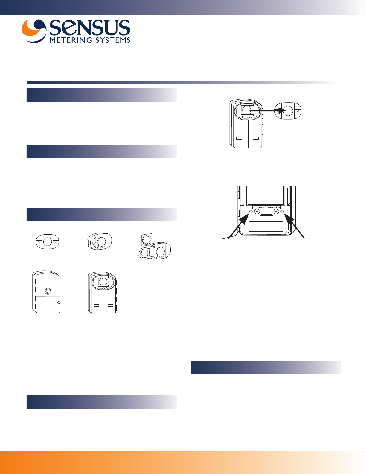
1. Sensus TouchPad
2. TouchPad Cover Assembly Complete
3. TouchPad Cover
4. TouchPad Fastener
5. TouchPad Cover Locking Clip
6. Model 510R2 Radio (Front View)
7. Model 5102 Radio TouchCoupler Enabled Assembly
(Rear View with TouchPad Cover)
Single Port – TouchCoupler Installation
1. Perform a TouchRead on TouchPad(s) to insure TouchRead to
the encoder works.
2. Taking a completely assembled Model 5102 Radio and Touch-
Coupler Spacer with TouchPad Cover, align the TouchPad
Cover over an installed Sensus TouchPad.
Important
General Information
Definitions
12
67
3
4
5
TouchCoupler - Installation Instructions
3. Place the unit over the TouchPad and press firmly until secure.
4. For additional support (optional), open the MXU door and pre-
drill the holes designed to fasten the unit to the wall. (Fastener
holes are located above the battery).
5. Secure the unit to the wall with screws.
6. Once unit is secured with the screws, close the door of the
MXU and tighten security screw until unit is firmly sealed.
7. Once the unit is closed and secured, begin the activation
process. (See Activate Radio section).
8. Coil excess wire and then secure to the body of the meter or
service line in a presentable manner.
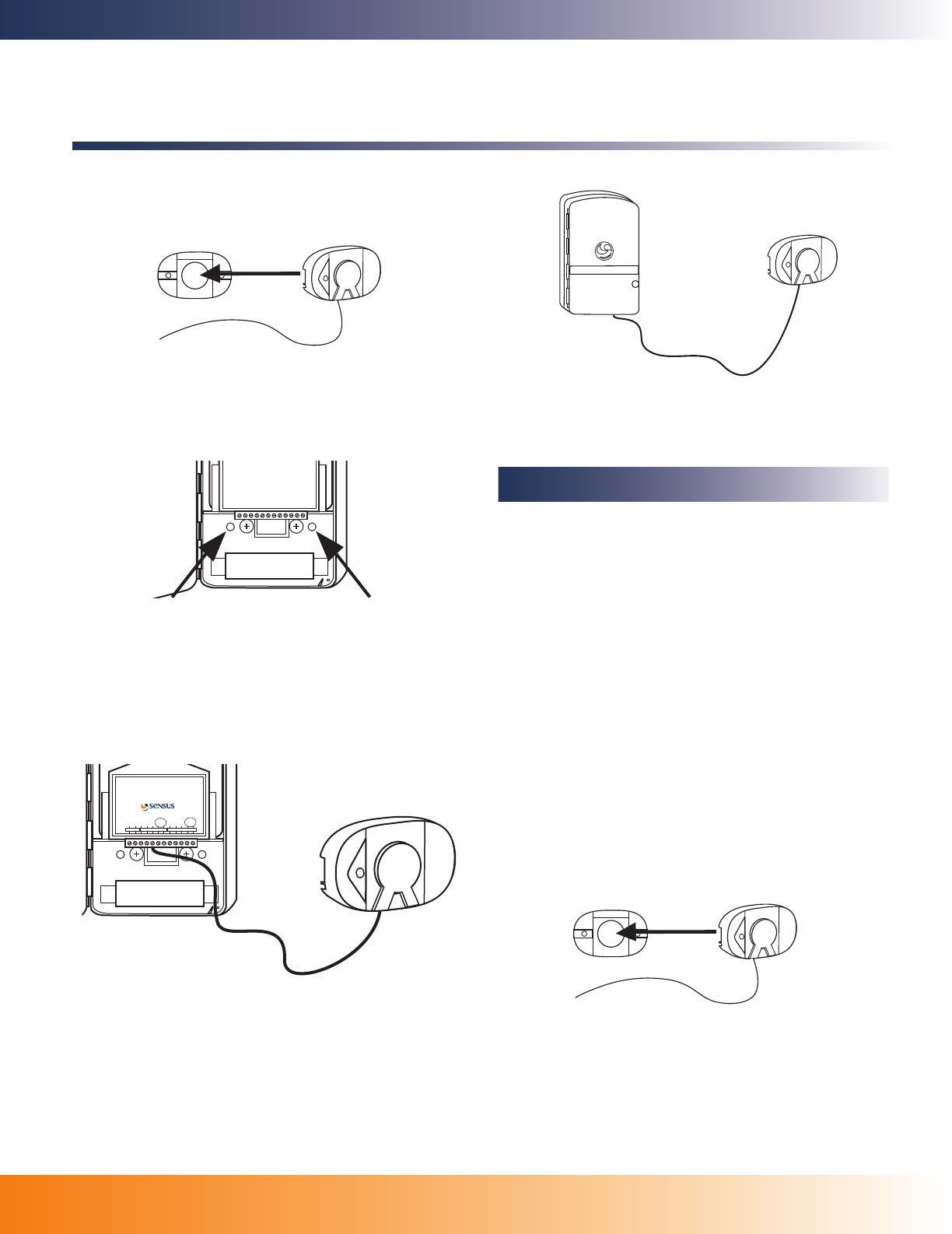
Single Port - Remote TouchCoupler
Installation
Remote TouchCoupler installations are an option when a direct
TouchCoupler (Sensus only) connection cannot be completed due
to physical limitations. Before proceeding with the installation of a
remote TouchCoupler application, be sure to find a location free
from obstacles that would interfere with the connection from the
TouchPad Cover to the MXU.
●
Wire stripping tool
●
Screwdriver - Small standard head for terminal connections
●
SR II security screw socket with 1/4" nut driver or ratchet wrench
●
Power drill and bit (1/4")
●
8 x 1" sheet metal screws
1. Find a suitable location for the installation where the TouchPad
Cover and MXU installation will be free from interference.
Note: If TouchPad is not already installed, install TouchPad allowing
enough room for the TouchPad Cover to be securely placed over
the installed TouchPad.
Recommended Tools and Materials
amr_321.fm Page 1 Tuesday, July 18, 2006 3:55 PM
AMR-XXX
2. Perform a TouchRead on TouchPad(s) to insure TouchRead to
the encoder works.
3. Place the remote TouchPad Cover firmly over the Sensus
TouchPad until secured.
4. Once the TouchPad Cover is secured on the TouchPad, find a
location close to the TouchPad Cover to install the MXU.
5. Place the MXU at the location for installation, with the door open,
mark the location to pre-drill the holes designed to fasten the
unit to the wall. (Fastener holes are located above the battery).
6. Remove the MXU from the wall and use a 1/4" drill bit to pre-drill
the fastener holes.
7. Place the unit on the wall and align the pre-drilled holes with the
fastener locations.
8. Secure the unit to the wall with screws.
9. Connect the wires from the TouchPad Cover to the coordinating
port terminals in the MXU labeled TouchCoupled.
Note: Red and black wires are non-polarized.
10. Once all the connections are complete, close the door of the
MXU and tighten security screw until unit is firmly sealed.
11. Once the units are secured, begin the activation process. (See
Activate Radio section).
BATTERY
Blue
Black &
White
Red
Green
Black
Red
Green
Black
RadioRead
PORT 1 PORT 2
Touch
Coupled
Touch
Coupled
Sensus Metering Systems Uniontown, PA 15401
Model 510R Pt. No. 539-61-537-51006T
M510R-D2-CMB-CMB-T
Patent Pending. Date 06/05
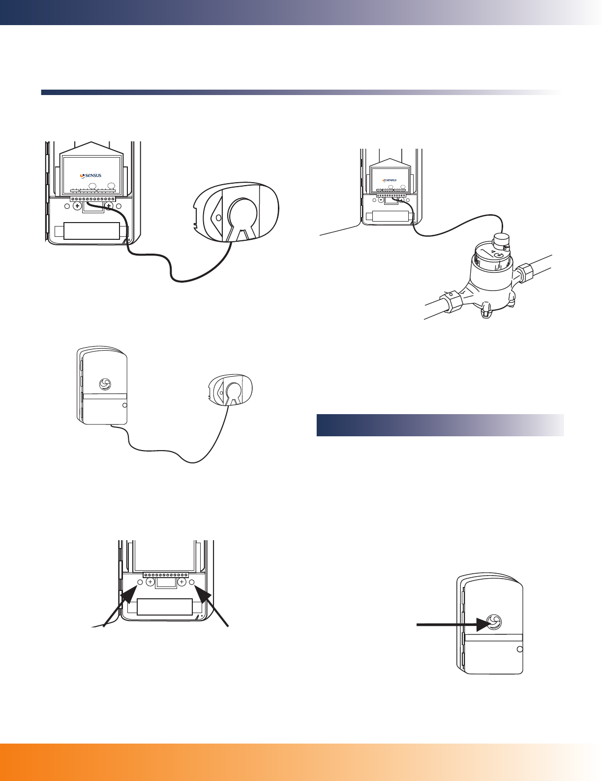
Dual Port – TouchCoupler Installation
●
Wire stripping tool
●
Screwdriver - Small standard head for terminal connections
●
SR II security screw socket with 1/4" nut driver or ratchet wrench
●
Power drill and bit (1/4")
●
8 x 1" sheet metal screws
1. Perform a TouchRead on TouchPad(s) to insure TouchRead to
the encoder works.
2. For new installations of dual ports, find a suitable location for an
installation where two TouchPads can be installed that will be free
from interference. The optimum distance should be less than 12"
otherwise wires may require field splicing. (For existing TouchPad
connections and second port is added, select a location for the
second TouchPad installation that will be free from interference).
3. Determine which of the two TouchPads will use the TouchPad
Cover only and which will use the TouchCoupler unit as the pri-
mary connection.
Note: If TouchPad is not already installed, install TouchPad allowing
enough room for the TouchPad Cover to be securely placed over
the installed TouchPad.
4. Place the remote TouchPad Cover firmly over the Sensus Touch-
Pad until secured.
5. With the MXU door open, place the MXU over the second Touch-
Pad location and press firmly until unit is secured to the Touch-
Pad. For additional support (optional), pre-drill the holes
designed to fasten the unit to the wall. (Fastener holes are
located above the battery). Secure the unit to the wall with
screws.
Note: If not already installed, install the second TouchPad allowing
enough room to connect the MXU to the TouchPad.
Recommended Tools and Materials
Installation Instructions-Draft
Page 2 of 4
Sensus RadioRead
Model 510R2 – Non Pit Unit
amr_321.fm Page 2 Tuesday, July 18, 2006 3:55 PM
AMR-XXX
Page 3 of 4
6. Connect the wires from the TouchPad Cover to the coordinating
port terminals in the MXU labeled TouchCoupled.
Note: Red and black wires are non-polarized.
7. Once all the connections are complete, close the door of the
MXU and tighten security screw until unit is firmly sealed.
8. Once the unit is closed and secured, begin the activation pro-
cess. (See Activate Radio section).
Single and Dual Port – Wired Installation
1. Place the MXU at the location for installation, with the door open,
mark the location to pre-drill the holes designed to fasten the unit
to the wall. (Fastener holes are located above the battery).
2. Remove the MXU from the wall and use a 1/4" drill bit to pre-drill
the fastener holes.
3. Place the unit on the wall and align the pre-drilled holes with the
fastener locations.
4. Secure the unit to the wall with screws.
5. Strip wires prior to inserting into terminal strip.
6. Connect the wires from the register to the coordinating port termi-
nals in the MXU. Wire connections to terminal strip are red to red,
black to black, and green to green.
BATTERY
Blue
Black &
White
Red
Green
Black
Red
Green
Black
RadioRead
PORT 1 PORT 2
Touch
Coupled
Touch
Coupled
Sensus Metering Systems Uniontown, PA 15401
Model 510R Pt. No. 539-61-537-51006T
M510R-D2-CMB-CMB-T
Patent Pending. Date 06/05
Note: For the Neptune ProRead encoder, the color coded wire
connections are not standard – For ProRead, connect the MXU red
to ProRead black, MXU green to ProRead red, and MXU black to
ProRead green.
7. Once all terminal connections are complete, close the door of the
MXU and tighten security screw until unit is firmly sealed.
8. Once the unit is closed and secured, begin the activation pro-
cess. (See Activate Radio section).
Note: if encoders or multiread modules are not connected to this radio,
the radio will not activate.
Once all meters are connected, the radio must be activated in order
for it to perform its function. To activate, using a TouchReader or
Model 4090 AutoGun, perform a TouchRead on the Programming/
TouchRead port (See picture below). To use TouchReader+ to acti-
vate, follow instructions below. During activation process, the radio
will determine what is connected to this unit automatically. This may
take up to 3-6 seconds depending if the unit is dual port capable
and what type of encoders are connected.
TouchReader+
1. If the TouchReader+ is not in Programmer Mode, press both Up
and Down arrow simultaneously to cycle through the different
modes.
BATTERY
Blue
Black &
White
Red
Green
Black
Red
Green
Black
RadioRead
PORT 1 PORT 2
Touch
Coupled
Touch
Coupled
Sensus Metering Systems Uniontown, PA 15401
Model 510R Pt. No. 539-61-537-51006T
M510R-D2-CMB-CMB-T
Patent Pending. Date 06/05
Activate Radio
Programming /
TouchRead
Installation Instructions-Draft
Sensus RadioRead
Model 510R2 – Non Pit Unit
amr_321.fm Page 3 Tuesday, July 18, 2006 3:55 PM
AMR-XXX
Page 4 of 4
Installation Instructions-Draft
Sensus RadioRead
Model 510R2 – Non Pit Unit
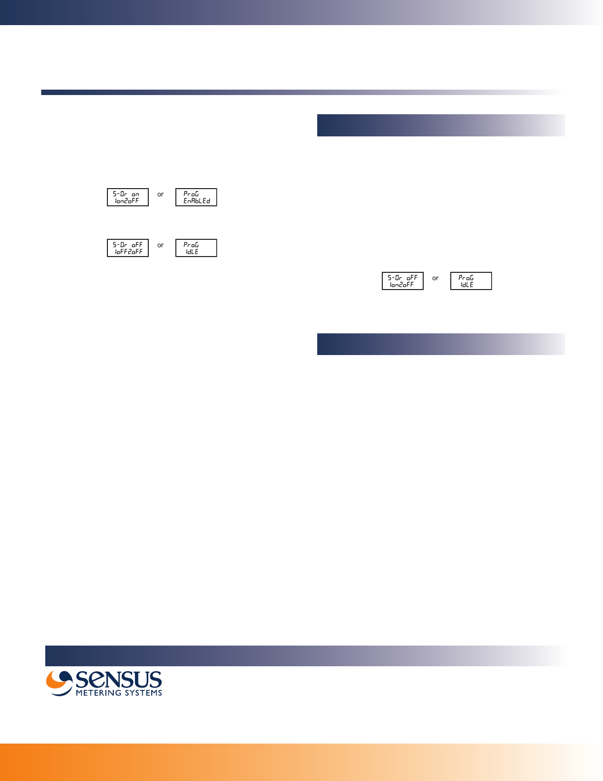
2. Once in Programmer Mode, pictured below, use the Up/Down
arrows until ENABLE is displayed.
3. Place the TouchReader+ Sensor on the Programming port of the
radio and press the Read button. This will send a message to
the radio to start the activation process. Keep TouchReader+ in
place until complete – messages will appear on the screen.
4. Once complete, the TouchReader+ will beep once upon suc-
cess and display the radio’s status.
If unsuccessful, the radio will remain in an idle state and the
TouchReader+ will beep twice and display the radio’s status.
TouchReader
1. The TouchReader will beep once indicating that the radio
acknowledged the TouchRead and is now detecting the type of
register connection.
2. After waiting approximately 3 seconds, perform another
TouchRead, if a read error occurs, the radio is still in detect
mode. Repeat this step again in 3 more seconds if read error
occurs.
3. If port detection is successful, the reading unit should provide
either a TouchRead reading (Sensus only) or a single beep to
indicate that the encoder is connected.
Note: TouchRead is not supported on Neptune registers.
AutoGun (ID type set to Factory ID – see AutoGun manual for
instructions)
1. The AutoGun will beep and display the ID with a
“0”
at the end.
This indicates that the radio acknowledged that TouchRead is
in inactive/idle mode "0". This will start the detecting process.
2. After waiting approximately 3 seconds, perform another
TouchRead, if a read error occurs, the radio is still in detect
mode. Repeat this step again in 3 more seconds.
3. If successful detection, the AutoGun will display either a
TouchRead reading (Sensus only) or
•
ID: 1
– which means a TouchRead was attempted on an
unsupported meter (Neptune).
•
ID: 2
– which means that the port was configured for a meter
type that supports TouchRead (Sensus only) but there was no
response from the meter.
4. If unsuccessful detection, the TouchRead will start the activation
process again. The ID on the AutoGun will display
“0”
similar to
the step 1 above.
Note: Once the radio is activated and it detects the type of register con-
nection, the only way to change its configuration to the correct
type of register connection is to deactivate the radio using a pro-
gramming tool and then re-activate the radio or use a program-
ming tool to reprogram the port manually.
TouchReader+
1. If the TouchReader+ is not in Programmer Mode, press both Up
and Down arrow simultaneously to cycle through the different
modes.
2. Once in Programmer Mode, pictured below, use the Up/Down
arrows until Deact is displayed.
3. Place the TouchReader+ Sensor on the Programming port of the
radio and press the Read button. This will send a message to the
radio to start the deactivation process. Keep TouchReader+ in
place until complete – messages will appear on the screen.
4. Once complete, the TouchReader+ will beep once upon success
and display the radio’s status.
If unsuccessful, the radio will remain in an active state and the
TouchReader+ will beep twice and display the radio’s status.
This equipment has been tested and found to comply with the limita-
tions for a Class B digital device, pursuant to Part 15 of the FCC
rules. These limits are designed to provide reasonable protection
against harmful interference in a residential installation. This equip-
ment generates uses and can radiate radio frequency energy and,
if not installed and used in accordance with these instructions, may
cause harmful interference to radio communications. However, there
is no guarantee that interference will not occur in a particular installa-
tion. If this equipment does cause harmful interference to radio and
television reception, which can be determined by turning the equip-
ment off and on, the user is encouraged to try to correct the interfer-
ence by one or more of the following measures:
●
Reorient or relocate the receiving device
●
Increase the separation between the equipment and receiver
●
Connect the equipment into an outlet on a circuit different from
that to which the receiver is connected
●
Consult the dealer or an experienced radio/TC technician
Warning: No party shall make any modifications or changes to the
Sensus Model 510R2 MXU (the equipment) without express
written consent of Sensus Metering Systems. Doing so could
result in the equipment becoming non-compliant with the
requirements of the Federal Communications Commission
Rules CFR47 part 15 and could void the user’s authority to
operate the equipment.
Deactivate Radio
FCC Compliance
AUTHORIZED SENSUS DISTRIBUTOR
P.O. Box 487 • 450 N. Gallatin Avenue
Uniontown, PA 15401
1-800-METER-IT • 1-800-638-3748
Fax: Direct to Factory
Local: 724-439-7729 • Toll Free: 1-800-888-2403
www.sensus.com (select "North America Water")
Email: h2oinfo@sensus.com
amr_321.fm Page 4 Tuesday, July 18, 2006 3:55 PM