Sensus Metering Systems 520C Transmitter for Utility Meter User Manual Sensus Model 520C User s Guide
Sensus Metering Systems Transmitter for Utility Meter Sensus Model 520C User s Guide
UserManual.wiki
>
Sensus Metering Systems
>
520C User Manual
User Manual
Navigation menu
Upload a User Manual
Namespaces
Wiki Guide
HTML
PDF
Info
Views
User Manual
Discussion / Help
Navigation
![Sensus Metering Systems-North America Inc. CellNet Water MTU User’s Guide 3 1. Introduction This document describes how to install, activate, operate and deactivate the CellNet Meter Transponder Unit (MTU). 1.1 Reference Documents The following documents are referenced by this document: [1] RF LAN1 Air Interface Specification (95-1501Rev. A), CellNet, 5 May 2004 [2] Preliminary – Protocol Data Unit Specification, PID 0x02, 0x03, 0x04 – Electric, Gas and Water Meter Packets Rev. C, CellNet, 5 May 2004 1.2 Open Issues •](https://usermanual.wiki/Sensus-Metering-Systems/520C/User-Guide-494140-Page-4.png)
![Sensus Metering Systems-North America Inc. CellNet Water MTU User’s Guide 5 2. CellNet Water MTU Overview The sections which follow provide a high-level functional description of the CellNet Water MTU. 2.1 Features The CellNet Water MTU provides the following features: 2.1.1 Field Configurable The CellNet Water MTU can be configured via the programming interface using the Touch Gun. Configurable parameters are as specified in [ref 2]. Note that configuration is limited to parameter settings that are consistent with the Marketing Specification – particularly with respect to battery life. Field re-configurability is not supported for this release, but will be supported in subsequent releases of this product. 2.1.2 Magnetic Switch Controlled Activation/Deactivation The CellNet Water MTU can be “activated” and “deactivated” by passing a magnet over a magnetic switch present on the endpoint. 2.1.3 Magnetic Switch Forced Transmission Once the CellNet Water MTU has been activated, it can be forced to transmit meter readings by passing a magnet over the magnetic switch. 2.1.4 Touch Coupled Register Interface The CellNet Water MTU communicates with the register via an inductive interface, making the endpoint/register connection easier to install and less prone to water damage due to incorrect installation. 2.1.5 Battery Life The CellNet Water MTU, when deployed as configured at the factory, will operate for [TBD] years.](https://usermanual.wiki/Sensus-Metering-Systems/520C/User-Guide-494140-Page-6.png)
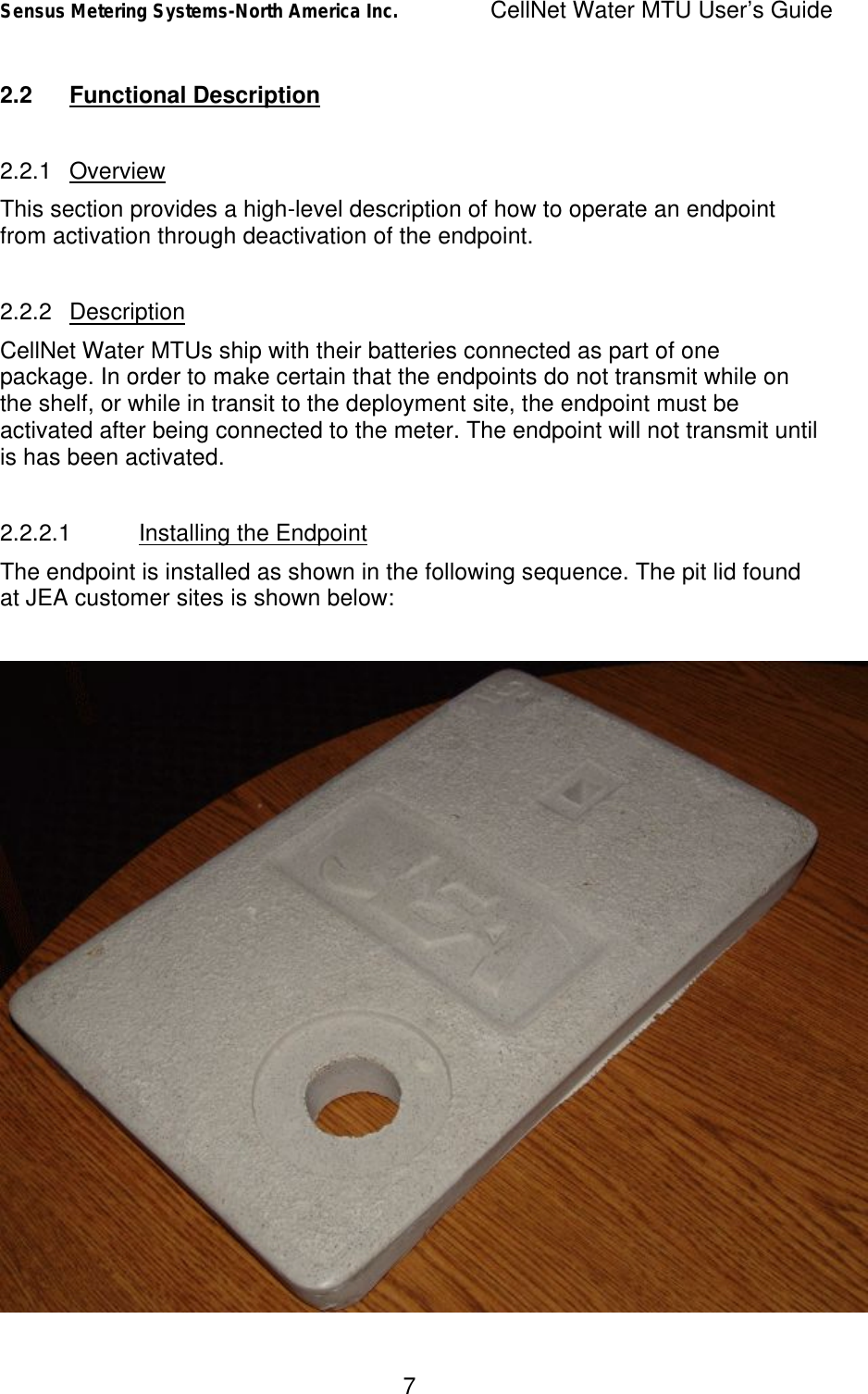
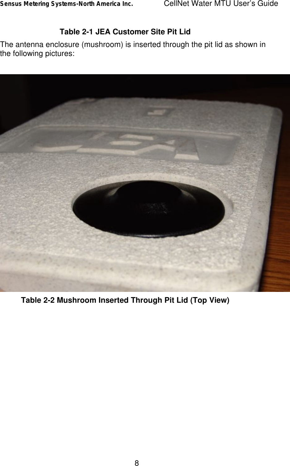
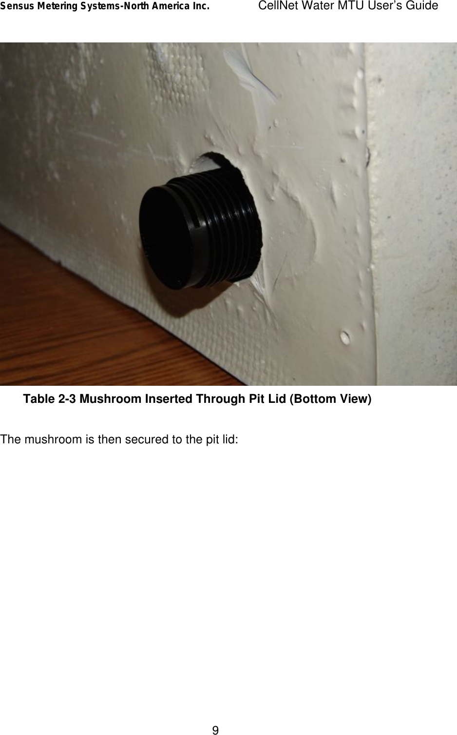
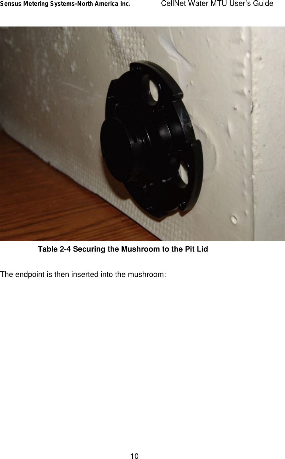
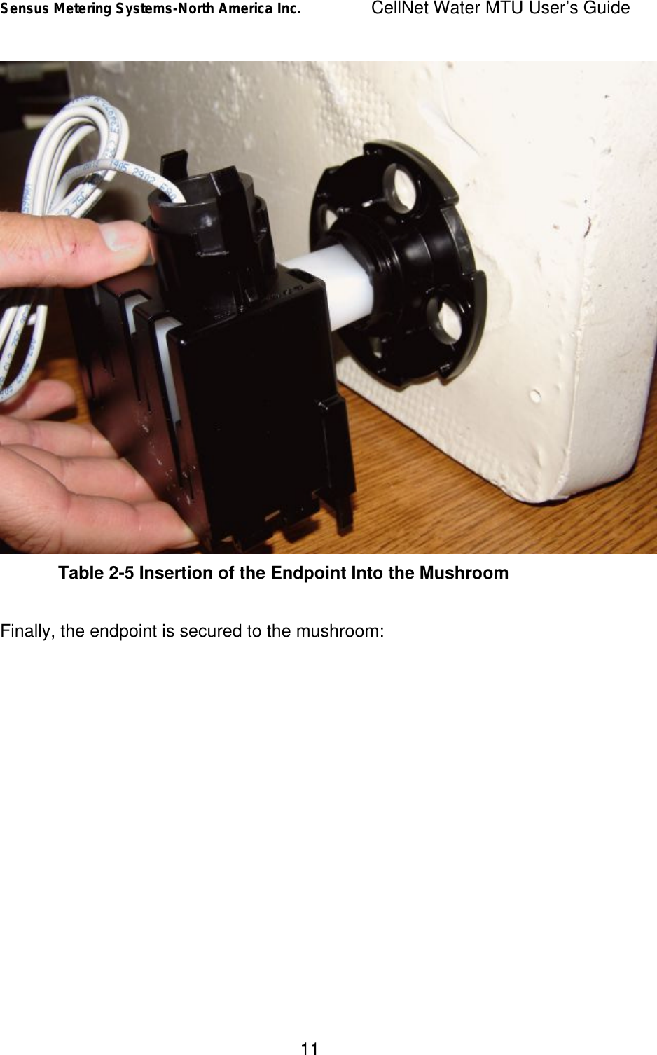
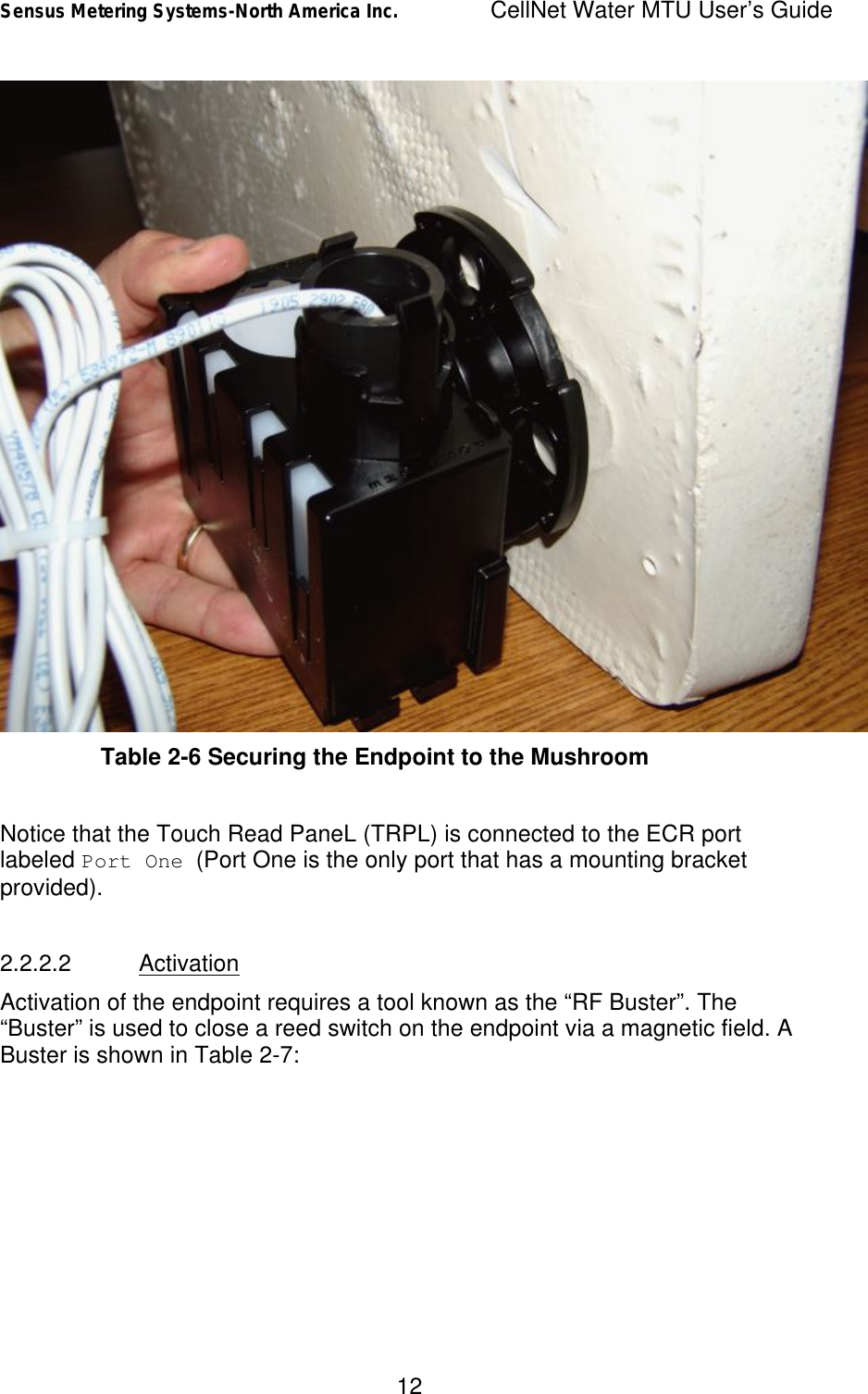
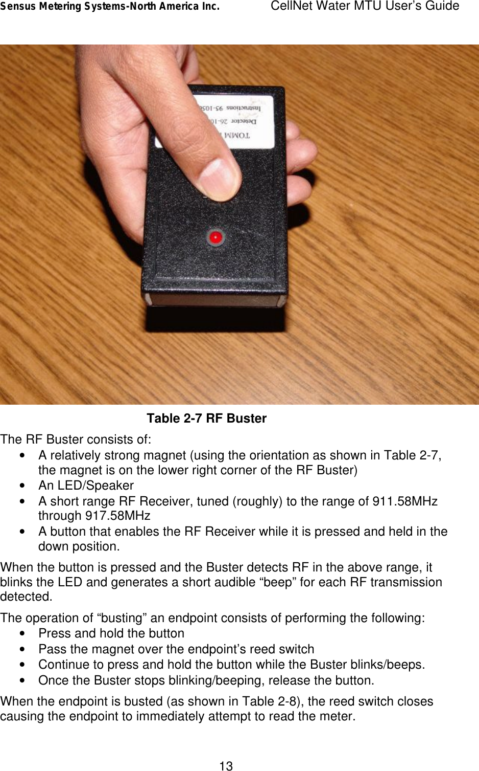
![Sensus Metering Systems-North America Inc. CellNet Water MTU User’s Guide 15 2.2.2.3 Operation Once the unit has been activated, it will read the meter and transmit Consumption data using the timing configured at the factory. Packets transmitted by each endpoint are uniquely identified by a 10 digit LAN Address. The 10 digit LAN Address of each endpoint can be found on the label applied to the endpoint enclosure, and can be queried through the programming interface. The default timing of RF transmissions from the CellNet Water MTUs, and the type of data transmitted, is as follows: • Consumption Data: Consumption data consists of the current cumulative meter reading. Consumption data is transmitted once every 15 minutes (15 minute intervals) • Administration Data: Administration data consists of the current cumulative meter reading, as well as the current configuration of the endpoint. Administration data is transmitted once every 60 minutes (1 hour intervals). In order to guarantee that all meters are able to be read over the course of a few hours, the meter read/RF transmissions are scheduled for a random time during each interval. Thus, the time between two consecutive Consumption data read/transmissions could be as short as a couple of seconds, or as long as 30 minutes. Consumption data contains only the current cumulative meter reading. The CellNet Network requires additional data to ensure the integrity of the network over time. Thus, in addition to the Consumption data that is transmitted 4 times per hour, Administrative data is transmitted once per hour. Administrative data provides the network with the configuration of the endpoint, in addition to a cumulative reading of the meter. Thus, the packets used to convey this data over the air are much larger than those used to convey Consumption data – and are transmitted less often. The meter read/RF transmission required to convey Administrative data over the network is randomized to occur at an arbitrary time within the hour. Thus, the time between two consecutive Administrative data read/transmissions could be as short as a couple of seconds, or as long as 2 hours. NOTE: The interval timing of the endpoint is configurable as per [ref 2]. Most endpoint parameters can be programmed via the Programming interface. For the remainder of this document, the reader may assume that any behavior mentioned can be configured via the programming interface unless otherwise indicated. NOTE: The re-programming of endpoint parameters should only be performed by knowledgeable technicians, as it can](https://usermanual.wiki/Sensus-Metering-Systems/520C/User-Guide-494140-Page-16.png)
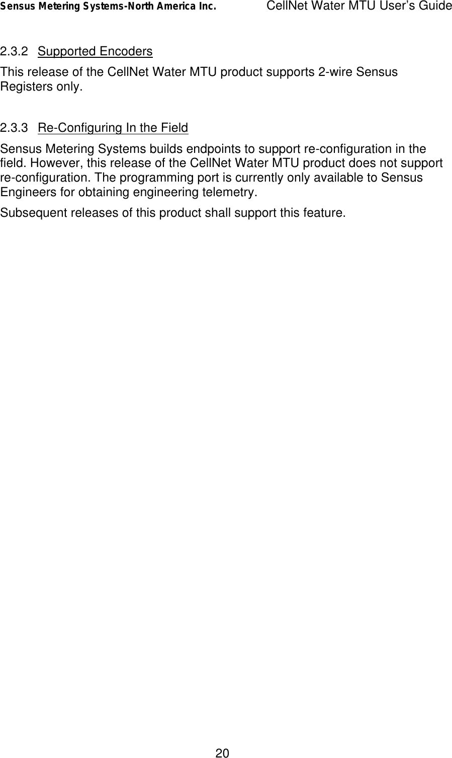
![Sensus Metering Systems-North America Inc. CellNet Water MTU User’s Guide 16 adversely affect the battery life of the endpoint. 2.2.2.4 Diagnostics [Ref 2] describes the diagnostics that are available via the CellNet RFLAN1 Protocol. For details on diagnostics, please refer to [ref 2]. When an endpoint detects an error condition, these conditions are reported via diagnostic bits in the RF LAN1 Frames transmitted by the endpoint. While the error condition exists, the endpoint will transmit packets with the corresponding diagnostic bit set. If the error condition clears, the bit will be set for the next 14 transmitted packets following the clearing of the condition. Thus, diagnostic bits will be set based on an error condition for a minimum of 15 packet transmissions. There are 4 diagnostic bits provided: Bit Description S Sensor Bit: This bit is set if an error occurs when reading the register. R Low Battery: This bit will be set when the endpoint has approximately 7 days of battery life left. W Watchdog Reset: This bit will be set at any time the unit resets. This will almost always be due to a watchdog reset, however might occur due to events such as a direct lightening strike. C Memory Corruption: This bit will be set if at any time the endpoint’s non-volatile storage becomes corrupted. Note that endpoints are built to recover gracefully from this situation, however may not be able to recover if a memory device is damaged (say as the result of a lightening strike), or if the product has reached the end of its useful life-cycle. Table 2-9 Description of Diagnostic Bits 2.2.2.5 Forcing a Meter Read Since a technician might have to wait up to 30 minutes to receive a reading of the meter based on the timing described above, the RF Buster can be used to force a read of the meter. An endpoint (that has been activated, and is properly connected to a register) will always respond to a magnet event in the manner previously described. 2.2.2.6 Deactivation](https://usermanual.wiki/Sensus-Metering-Systems/520C/User-Guide-494140-Page-17.png)