Sensus Metering Systems 520C Transmitter for Utility Meter User Manual Sensus Model 520C User s Guide
Sensus Metering Systems Transmitter for Utility Meter Sensus Model 520C User s Guide
User Manual

Model 520C User’s Guide
Revision 1.0, 13 September, 2004
Sensus Metering Systems-North America Inc.
This document contains proprietary information. It may not be copied,
transmitted or distributed, in whole or in part, without the consent of Sensus
Metering Systems-North America Inc.

Sensus Metering Systems-North America Inc. CellNet Water MTU User’s Guide
1
REVISION SUMMARY
Date Author Change Description
12 August, 2004 GM/CP/AN
Baseline
13 September, 2004
GM Removed references to Register wiring. Cleanup.
Sensus Metering Systems-North America Inc. CellNet Water MTU User’s Guide
2
TABLE OF CONTENTS
1. INTRODUCTION ......................................................................................................................................3
1.1 REFERENCE DOCUMENTS.....................................................................................................................3
1.2 OPEN ISSUES........................................................................................................................................3
1.3 GLOSSARY ...........................................................................................................................................4
2. CELLNET WATER MTU OVERVIEW..................................................................................................5
2.1 FEATURES ............................................................................................................................................5
2.1.1 Field Configurable.....................................................................................................................................5
2.1.2 Magnetic Switch Controlled Activation/Deactivation...............................................................................5
2.1.3 Magnetic Switch Forced Transmission......................................................................................................5
2.1.4 Touch Coupled Register Interface .............................................................................................................5
2.1.5 Battery Life................................................................................................................................................5
2.1.6 FCC ...........................................................................................................................................................6
2.2 FUNCTIONAL DESCRIPTION ..................................................................................................................7
2.2.1 Overview ...................................................................................................................................................7
2.2.2 Description ................................................................................................................................................7
2.2.2.1 Installing the Endpoint.........................................................................................................................7
2.2.2.2 Activation...........................................................................................................................................12
2.2.2.3 Operation............................................................................................................................................15
2.2.2.4 Diagnostics.........................................................................................................................................16
2.2.2.5 Forcing a Meter Read.........................................................................................................................16
2.2.2.6 Deactivation .......................................................................................................................................16
2.2.3 Summary..................................................................................................................................................18
2.3 CONFIGURATION ................................................................................................................................19
2.3.1 Configuration as Shipped ........................................................................................................................19
2.3.2 Supported Encoders.................................................................................................................................20
2.3.3 Re-Configuring In the Field....................................................................................................................20

Sensus Metering Systems-North America Inc. CellNet Water MTU User’s Guide
3
1. Introduction
This document describes how to install, activate, operate and deactivate the
CellNet Meter Transponder Unit (MTU).
1.1 Reference Documents
The following documents are referenced by this document:
[1] RF LAN1 Air Interface Specification (95-1501Rev. A), CellNet,
5 May 2004
[2] Preliminary – Protocol Data Unit Specification, PID 0x02, 0x03, 0x04
– Electric, Gas and Water Meter Packets Rev. C, CellNet, 5 May 2004
1.2 Open Issues
•

Sensus Metering Systems-North America Inc. CellNet Water MTU User’s Guide
4
1.3 Glossary
BPSK Binary Phase Shift Keying
CRC Cyclic Redundancy Check
ECR Electronically Controlled Register
FCC Federal Communications Commission
JEA Jacksonville Electric Authority
kHz Kilohertz
LAN Local Area Network
LED Light Emitting Diode
MHz Megahertz
MTU Meter Transmitter Unit
OOK On-Off Keying
RAD-40 CellNet proprietary compression scheme
RF Radio Frequency
TRPL Touch Read Pit-Lid
TX Transmit

Sensus Metering Systems-North America Inc. CellNet Water MTU User’s Guide
5
2. CellNet Water MTU Overview
The sections which follow provide a high-level functional description of the
CellNet Water MTU.
2.1 Features
The CellNet Water MTU provides the following features:
2.1.1 Field Configurable
The CellNet Water MTU can be configured via the programming interface using
the Touch Gun. Configurable parameters are as specified in [ref 2]. Note that
configuration is limited to parameter settings that are consistent with the
Marketing Specification – particularly with respect to battery life.
Field re-configurability is not supported for this release, but will be supported in
subsequent releases of this product.
2.1.2 Magnetic Switch Controlled Activation/Deactivation
The CellNet Water MTU can be “activated” and “deactivated” by passing a
magnet over a magnetic switch present on the endpoint.
2.1.3 Magnetic Switch Forced Transmission
Once the CellNet Water MTU has been activated, it can be forced to transmit
meter readings by passing a magnet over the magnetic switch.
2.1.4 Touch Coupled Register Interface
The CellNet Water MTU communicates with the register via an inductive
interface, making the endpoint/register connection easier to install and less
prone to water damage due to incorrect installation.
2.1.5 Battery Life
The CellNet Water MTU, when deployed as configured at the factory, will
operate for [TBD] years.

Sensus Metering Systems-North America Inc. CellNet Water MTU User’s Guide
6
2.1.6 FCC
The CellNet Water MTU is FCC Approved. The CellNet Water MTU transmits
using frequencies in the 900MHz ISM band and as such deployment of the
CellNet Water MTU does not require an FCC license.
Changes or modifications not expressly approved by Sensus Metering
Systems could void the user's authority to operate the equipment.
To meet FCC RF exposure requirements a distance of at least 20 cm (8
inches) must be maintained between the transmit antenna and all
persons.
Sensus Metering Systems-North America Inc. CellNet Water MTU User’s Guide
7
2.2 Functional Description
2.2.1 Overview
This section provides a high-level description of how to operate an endpoint
from activation through deactivation of the endpoint.
2.2.2 Description
CellNet Water MTUs ship with their batteries connected as part of one
package. In order to make certain that the endpoints do not transmit while on
the shelf, or while in transit to the deployment site, the endpoint must be
activated after being connected to the meter. The endpoint will not transmit until
is has been activated.
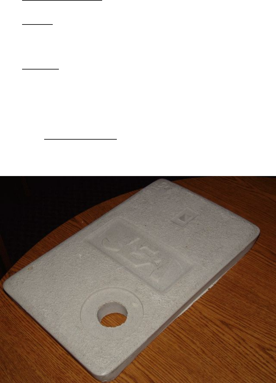
2.2.2.1 Installing the Endpoint
The endpoint is installed as shown in the following sequence. The pit lid found
at JEA customer sites is shown below:
Sensus Metering Systems-North America Inc. CellNet Water MTU User’s Guide
8
Table 2-1 JEA Customer Site Pit Lid
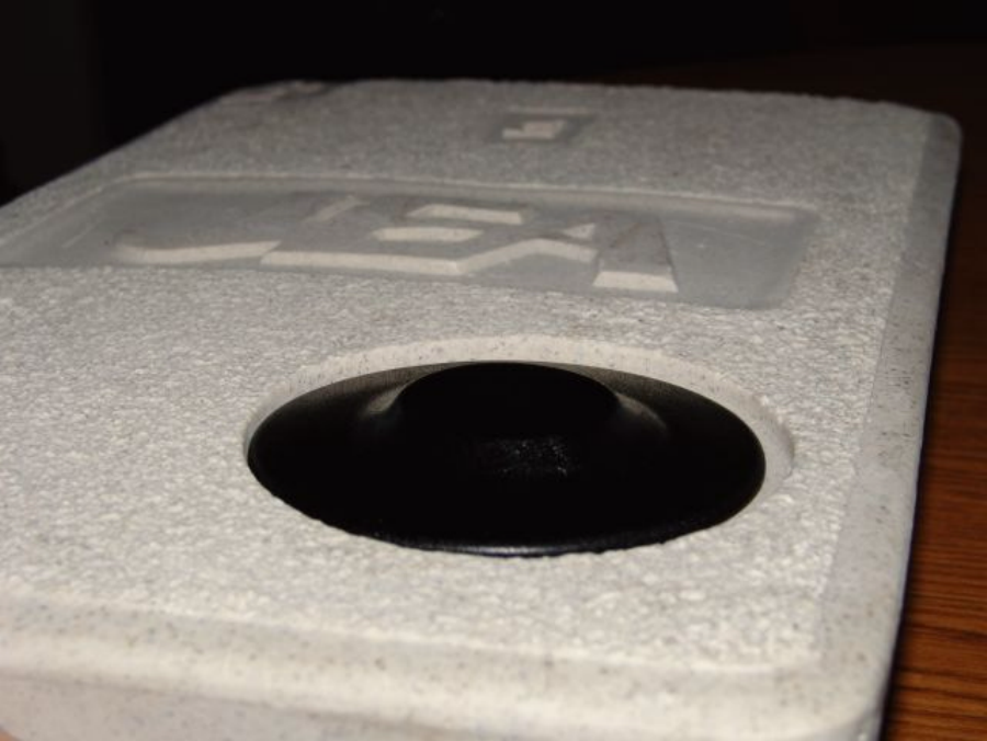
The antenna enclosure (mushroom) is inserted through the pit lid as shown in
the following pictures:
Table 2-2 Mushroom Inserted Through Pit Lid (Top View)
Sensus Metering Systems-North America Inc. CellNet Water MTU User’s Guide
9
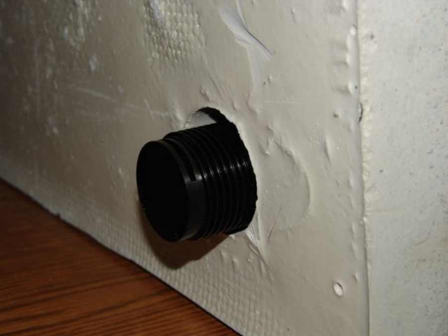
Table 2-3 Mushroom Inserted Through Pit Lid (Bottom View)
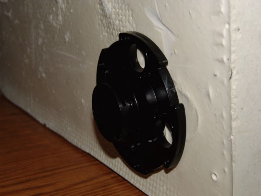
The mushroom is then secured to the pit lid:
Sensus Metering Systems-North America Inc. CellNet Water MTU User’s Guide
10
Table 2-4 Securing the Mushroom to the Pit Lid
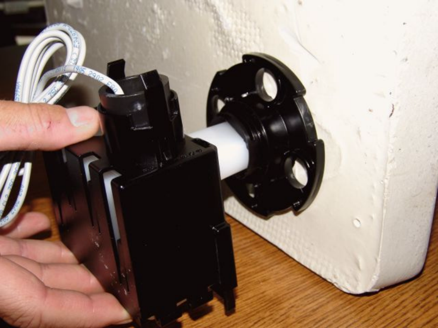
The endpoint is then inserted into the mushroom:
Sensus Metering Systems-North America Inc. CellNet Water MTU User’s Guide
11
Table 2-5 Insertion of the Endpoint Into the Mushroom
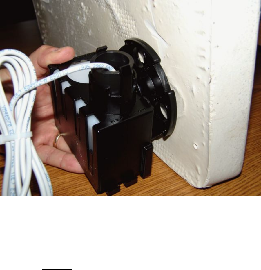
Finally, the endpoint is secured to the mushroom:
Sensus Metering Systems-North America Inc. CellNet Water MTU User’s Guide
12
Table 2-6 Securing the Endpoint to the Mushroom
Notice that the Touch Read PaneL (TRPL) is connected to the ECR port
labeled Port One (Port One is the only port that has a mounting bracket
provided).
2.2.2.2 Activation
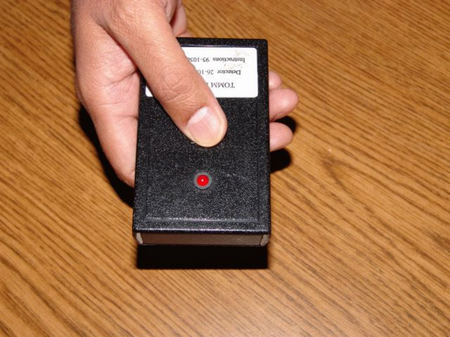
Activation of the endpoint requires a tool known as the “RF Buster”. The
“Buster” is used to close a reed switch on the endpoint via a magnetic field. A
Buster is shown in Table 2-7:
Sensus Metering Systems-North America Inc. CellNet Water MTU User’s Guide
13
Table 2-7 RF Buster
The RF Buster consists of:
• A relatively strong magnet (using the orientation as shown in Table 2-7,
the magnet is on the lower right corner of the RF Buster)
• An LED/Speaker
• A short range RF Receiver, tuned (roughly) to the range of 911.58MHz
through 917.58MHz
• A button that enables the RF Receiver while it is pressed and held in the
down position.
When the button is pressed and the Buster detects RF in the above range, it
blinks the LED and generates a short audible “beep” for each RF transmission
detected.
The operation of “busting” an endpoint consists of performing the following:
• Press and hold the button
• Pass the magnet over the endpoint’s reed switch
• Continue to press and hold the button while the Buster blinks/beeps.
• Once the Buster stops blinking/beeping, release the button.
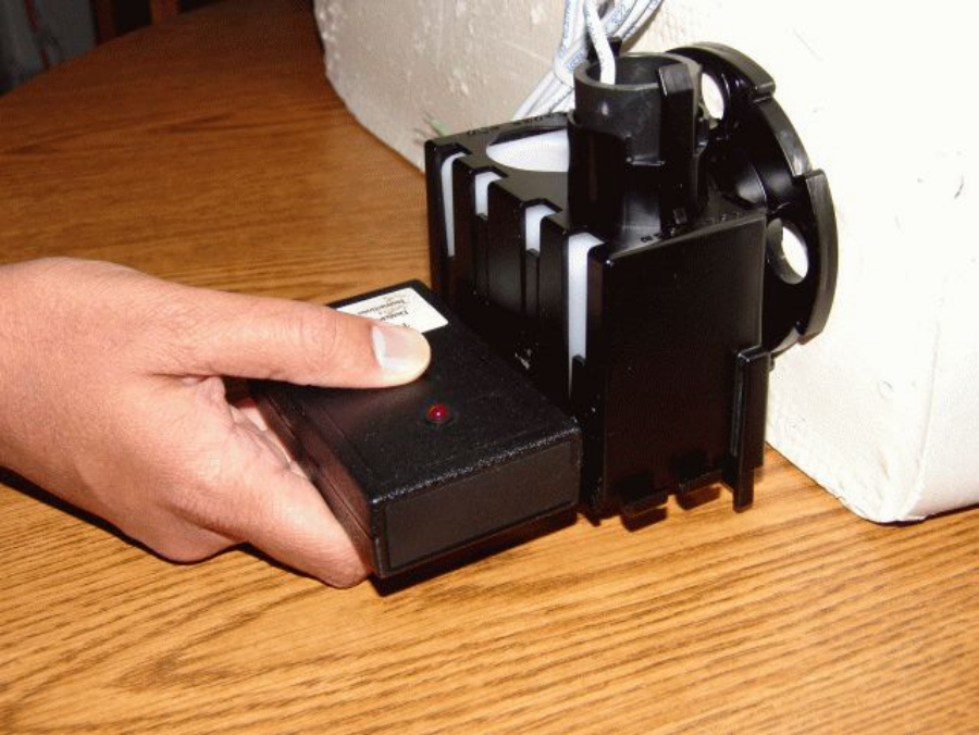
When the endpoint is busted (as shown in Table 2-8), the reed switch closes
causing the endpoint to immediately attempt to read the meter.
Sensus Metering Systems-North America Inc. CellNet Water MTU User’s Guide
14
Table 2-8 “Busting” the Endpoint
If the register has been correctly connected to the endpoint, the meter will be
read successfully, and the meter reading will be transmitted to the network 10
times. Thus, following a successful installation of the endpoint, busting the
endpoint will result in 10 blinks of the LED where each blink is associated by an
audible beep. The unit is now activated.
NOTE: In the busting sequence described
above, the meter is read just once prior to
transmission of the first RF packet. The same
meter reading is transmitted 10 times.
If the register has not been correctly connected to the endpoint, the meter will
not be read successfully upon being busted. In this case, the endpoint will not
activate upon closure of the reed switch, and thus will not transmit. Therefore,
until the RF Buster indicates that the unit has been activated, the technician
must assume that the endpoint has not been correctly installed.

Sensus Metering Systems-North America Inc. CellNet Water MTU User’s Guide
15
2.2.2.3 Operation
Once the unit has been activated, it will read the meter and transmit
Consumption data using the timing configured at the factory. Packets
transmitted by each endpoint are uniquely identified by a 10 digit LAN Address.
The 10 digit LAN Address of each endpoint can be found on the label applied to
the endpoint enclosure, and can be queried through the programming interface.
The default timing of RF transmissions from the CellNet Water MTUs, and the
type of data transmitted, is as follows:
• Consumption Data: Consumption data consists of the current
cumulative meter reading. Consumption data is transmitted once every
15 minutes (15 minute intervals)
• Administration Data: Administration data consists of the current
cumulative meter reading, as well as the current configuration of the
endpoint. Administration data is transmitted once every 60 minutes (1
hour intervals).
In order to guarantee that all meters are able to be read over the course of a
few hours, the meter read/RF transmissions are scheduled for a random time
during each interval. Thus, the time between two consecutive Consumption
data read/transmissions could be as short as a couple of seconds, or as long
as 30 minutes.
Consumption data contains only the current cumulative meter reading. The
CellNet Network requires additional data to ensure the integrity of the network
over time. Thus, in addition to the Consumption data that is transmitted 4 times
per hour, Administrative data is transmitted once per hour.
Administrative data provides the network with the configuration of the endpoint,
in addition to a cumulative reading of the meter. Thus, the packets used to
convey this data over the air are much larger than those used to convey
Consumption data – and are transmitted less often.
The meter read/RF transmission required to convey Administrative data over
the network is randomized to occur at an arbitrary time within the hour. Thus,
the time between two consecutive Administrative data read/transmissions could
be as short as a couple of seconds, or as long as 2 hours.
NOTE: The interval timing of the endpoint is
configurable as per [ref 2]. Most endpoint
parameters can be programmed via the
Programming interface.
For the remainder of this document, the reader may assume that any behavior
mentioned can be configured via the programming interface unless otherwise
indicated.
NOTE: The re-programming of endpoint
parameters should only be performed by
knowledgeable technicians, as it can

Sensus Metering Systems-North America Inc. CellNet Water MTU User’s Guide
16
adversely affect the battery life of the
endpoint.
2.2.2.4 Diagnostics
[Ref 2] describes the diagnostics that are available via the CellNet RFLAN1
Protocol. For details on diagnostics, please refer to [ref 2].
When an endpoint detects an error condition, these conditions are reported via
diagnostic bits in the RF LAN1 Frames transmitted by the endpoint. While the
error condition exists, the endpoint will transmit packets with the corresponding
diagnostic bit set. If the error condition clears, the bit will be set for the next 14
transmitted packets following the clearing of the condition. Thus, diagnostic bits
will be set based on an error condition for a minimum of 15 packet
transmissions.
There are 4 diagnostic bits provided:
Bit
Description
S Sensor Bit: This bit is set if an error occurs when reading the register.
R Low Battery: This bit will be set when the endpoint has approximately 7
days of battery life left.
W Watchdog Reset: This bit will be set at any time the unit resets. This will
almost always be due to a watchdog reset, however might occur due to
events such as a direct lightening strike.
C Memory Corruption: This bit will be set if at any time the endpoint’s non-
volatile storage becomes corrupted. Note that endpoints are built to
recover gracefully from this situation, however may not be able to recover
if a memory device is damaged (say as the result of a lightening strike), or
if the product has reached the end of its useful life-cycle.
Table 2-9 Description of Diagnostic Bits
2.2.2.5 Forcing a Meter Read
Since a technician might have to wait up to 30 minutes to receive a reading of
the meter based on the timing described above, the RF Buster can be used to
force a read of the meter. An endpoint (that has been activated, and is properly
connected to a register) will always respond to a magnet event in the manner
previously described.
2.2.2.6 Deactivation
Sensus Metering Systems-North America Inc. CellNet Water MTU User’s Guide
17
Units that are to be removed from the field must be deactivated. In order to
swap out a meter, the unit must have the meter removed, be deactivated, have
the new meter connected, and then be activated.
In order to deactivate a unit, the following steps must be taken:
• The endpoint must be disconnected from the meter
• The endpoint must then be busted
Busting an endpoint forces a read of the meter. When an endpoint
unsuccessfully attempts to read a meter due to a magnet event, it will transmit
3 Magnet Packets (where the cumulative reading field is set to 0x00AAAAAA)
and deactivate. In order to activate this unit in the future, the activation
procedure described previously must be repeated. The unit will not transmit
again until it has been activated. This can be verified by busting the unit again.
The Buster will not beep/blink in response to being busted once it has been
deactivated as long as there is no register connected to the device.
NOTE: It is critical that the technician
properly deactivate the unit prior to taking it
out of service. Failure to properly deactivate
the unit will result in the transmission of data
(with the previously described timing) until
the unit’s battery life has been exceeded. This
can have detrimental effects on the CellNet
Network, particularly if the device transmits
when in a moving vehicle from different
locations.
It is important to understand that once an endpoint is activated, there may be
times when a given read of the meter is unsuccessful. This will not result in the
deactivation of the endpoint. Only an unsuccessful meter read in response to a
magnet event will deactivate the device.

Sensus Metering Systems-North America Inc. CellNet Water MTU User’s Guide
18
2.2.3 Summary
The following table summarizes the behavior described in the previous
sections:
State When
Magnet Event
Occurs
State of Connection
to Register Response to
Magnet Event State Following
Magnet Event
De-activated Not Connected (or
improperly Connected) No Reponse De-activated
(unchanged)
De-activated Connected Buster
Blinks/Beeps
10 times
Activated
Activated Disconnected Buster
Blinks/Beeps 3
times
De-activated
Activated Connected Buster
Blinks/Beeps
10 times
Activated
(unchanged)
Table 2-10 Endpoint Activation/Deactivation State Summary

Sensus Metering Systems-North America Inc. CellNet Water MTU User’s Guide
19
2.3 Configuration
This section will describe how the board is configured as shipped, as well as
how it is configured in the field.
2.3.1 Configuration as Shipped
The following table describes the configuration of the endpoint as shipped:
Configuration
Parameter Default Configuration
Operating Mode Consumption Only
Interval Period 15 minutes
Administrative
Interval Period 1 hour
Alarm Count 15
Hardware
Revision 1
Firmware
Revision 0.37 (may change prior to shipping)
Scaling Constant 1
Max Pulse Rate NA
Super Tx 1
# Digits 8
Manufacturer ID 0
Product ID ???
Cumulative Meter
Reading Data
Format
4 bytes, Binary Coded Decimal (first two bytes are always
0). Digits encoded as 0xE indicate digit could not be read.
Device ID Field RAD-40 encoding of the ASCII-Decimal version of the
LAN Address, padded to 10 digits with zeroes to the left,
padded to 18 characters with spaces on the right.
Transmit
Frequency 917.58MHz +/-10kHz
Default PN Code x6+x1+1 (CellNet RFLAN1 Spread Spectrum Channel #1)
Table 2-11 Summary of Configurable Parameters

Sensus Metering Systems-North America Inc. CellNet Water MTU User’s Guide
20
2.3.2 Supported Encoders
This release of the CellNet Water MTU product supports 2-wire Sensus
Registers only.
2.3.3 Re-Configuring In the Field
Sensus Metering Systems builds endpoints to support re-configuration in the
field. However, this release of the CellNet Water MTU product does not support
re-configuration. The programming port is currently only available to Sensus
Engineers for obtaining engineering telemetry.
Subsequent releases of this product shall support this feature.