Sensus Metering Systems 520R 900MHz DTS RF Module User Manual Model 520R User Draft
Sensus Metering Systems 900MHz DTS RF Module Model 520R User Draft
UserManual.wiki
>
Sensus Metering Systems
>
520R User Manual
>
User Manual 520R
Contents
1.
Users Manual 510R
2.
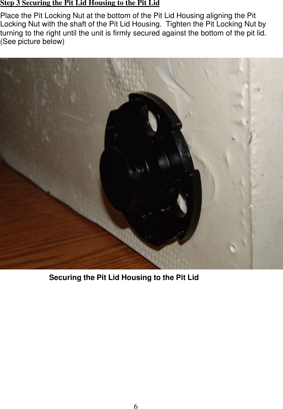
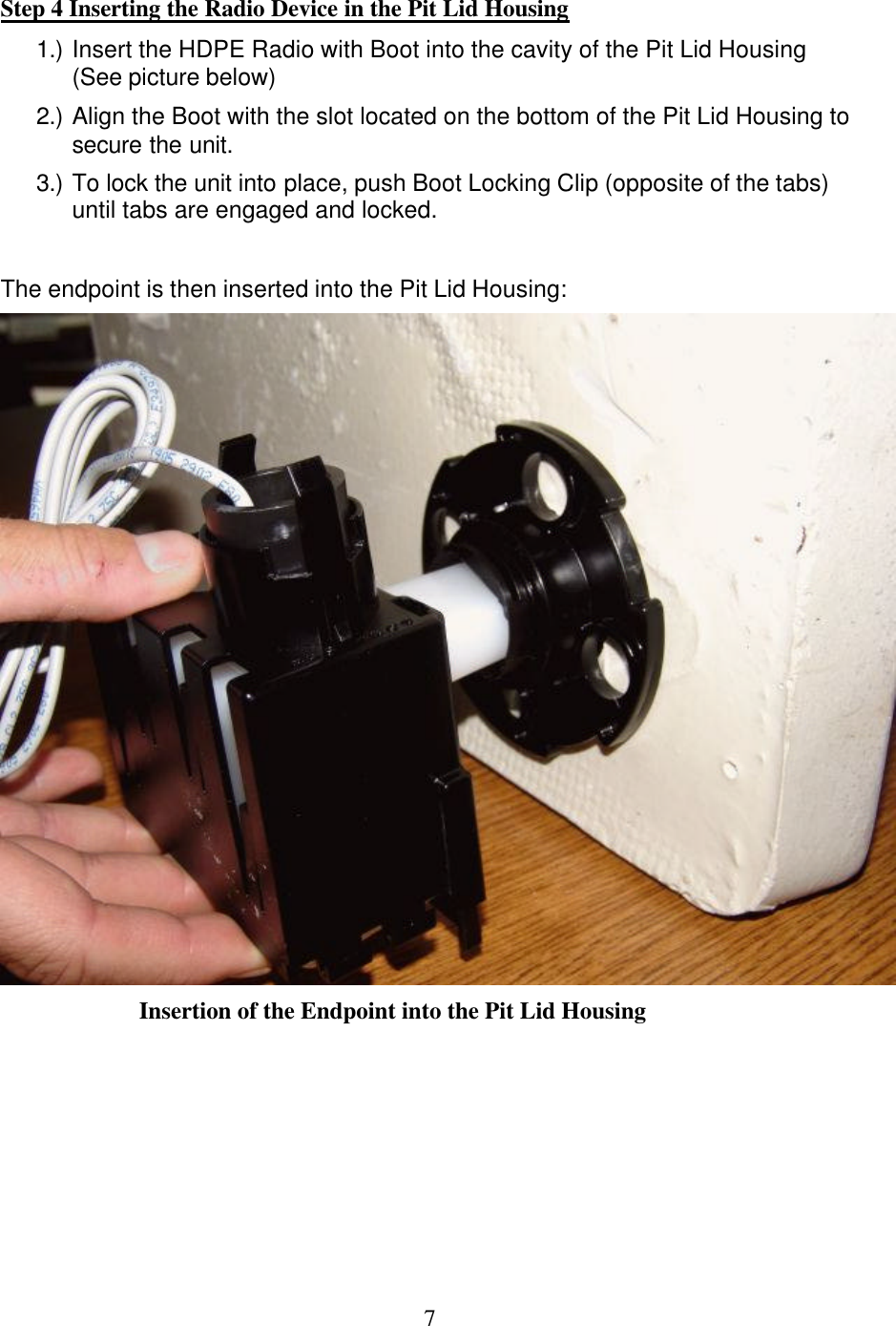
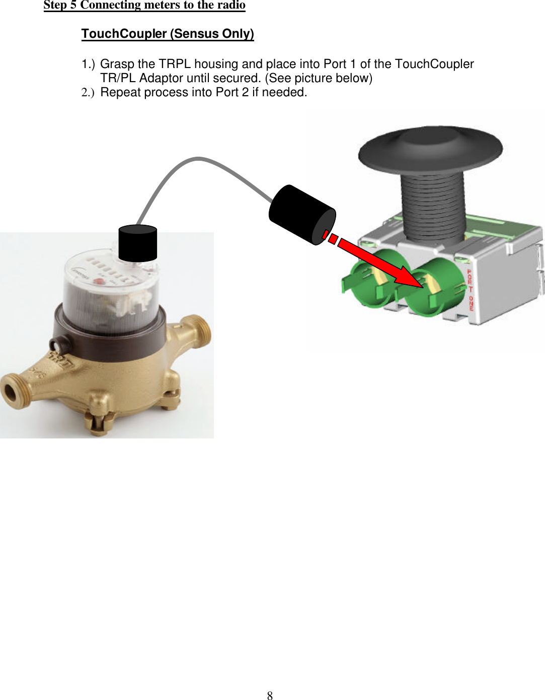
User Manual 520R
User Manual 520R
Navigation menu
Upload a User Manual
Namespaces
Wiki Guide
HTML
PDF
Info
Views
User Manual
Discussion / Help
Navigation