Sensus Metering Systems 520R 900MHz DTS RF Module User Manual Model 520R User Draft
Sensus Metering Systems 900MHz DTS RF Module Model 520R User Draft
Contents
- 1. Users Manual 510R
- 2. User Manual 520R
User Manual 520R

Model 520 Installation Instructions
2
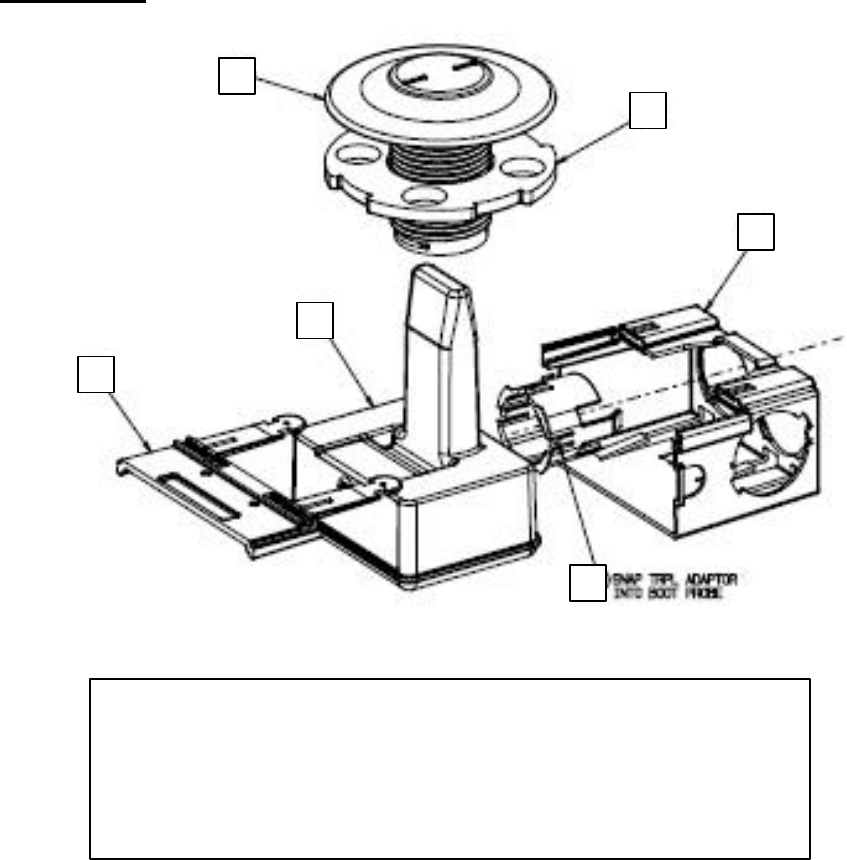
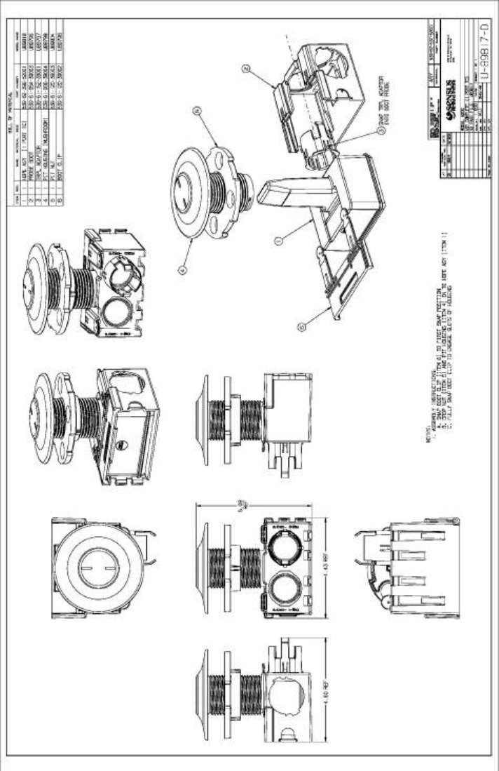
Definitions
1
–
HDPE Radio
2 – Boot
3 – TouchCoupler TR/PL Adaptor (TouchCoupler enabled units only)
4 – Pit Lid Housing
5 – Pit Locking Nut
6 – Boot Locking Clip
4
5
1
2
6
3

3
Table of Contents
Step 1 Disassemble 520 Unit ______________________________________________ 4
Step 2 Inserting the Pit Lid Housing________________________________________ 5
Step 3 Securing the Pit Lid Housing to the Pit Lid_____________________________ 6
Step 4 Inserting the Radio Device in the Pit Lid Housing_______________________ 7
Step 5 Connecting meters to the radio_______________________________________ 8
Appendix A: __________________________________________________________ 12
Appendix B: Regulatory Information_____________________________________ 14
4
Step 1 Disassemble 520 Unit
1.) Disassemble the model 520 unit to begin the installation procedure.
Unlock the radio device by pressing down on the two tabs on the Boot
Locking Clip facing the port side connections. Once the tabs are
depressed, slide the Boot Locking Clip partially out until the Boot
Locking Clip disengages from the Pit Lid Housing.
2.) Slide out the HDPE Radio and Boot from the Pit Lid Housing.
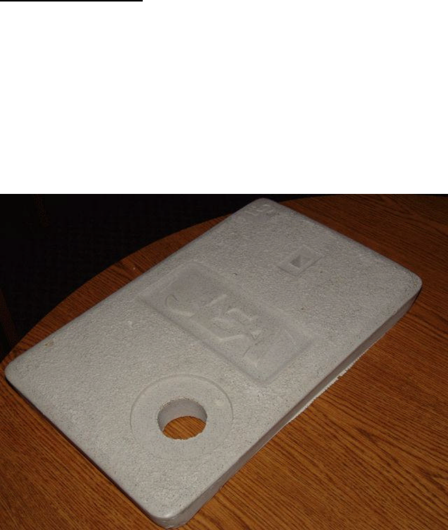
3.) Remove the Pit Locking Nut from the underneath of the Pit Lid Housing
by turning the Nut to the left.
Sample pit lid is shown below:
5
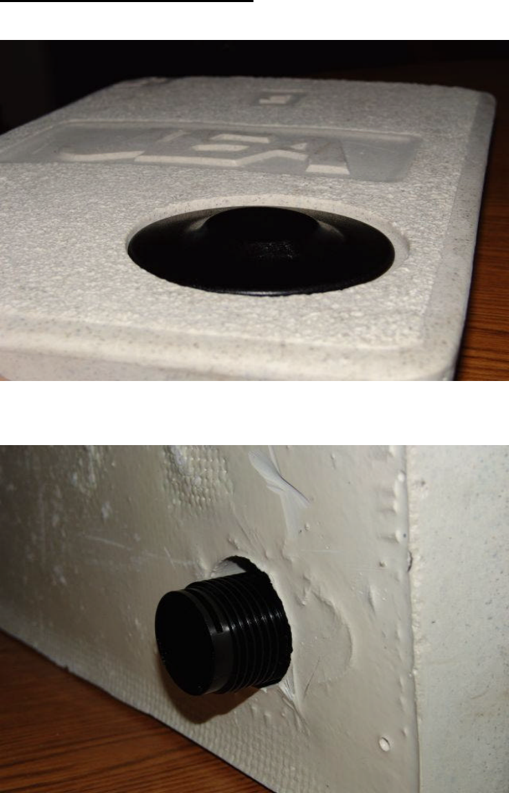
Step 2 Inserting the Pit Lid Housing
Place the Pit Lid Housing thru the pre-drilled hole in the top of the pit lid.
Pit Lid Housing Inserted Through Pit Lid (Top View)
Pit Lid Housing Inserted Through Pit Lid (Bottom View)
6
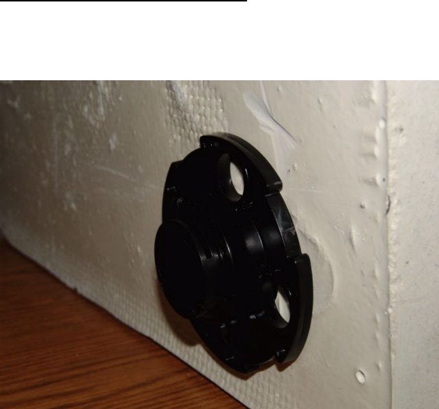
Step 3 Securing the Pit Lid Housing to the Pit Lid
Place the Pit Locking Nut at the bottom of the Pit Lid Housing aligning the Pit
Locking Nut with the shaft of the Pit Lid Housing. Tighten the Pit Locking Nut by
turning to the right until the unit is firmly secured against the bottom of the pit lid.
(See picture below)
Securing the Pit Lid Housing to the Pit Lid
7
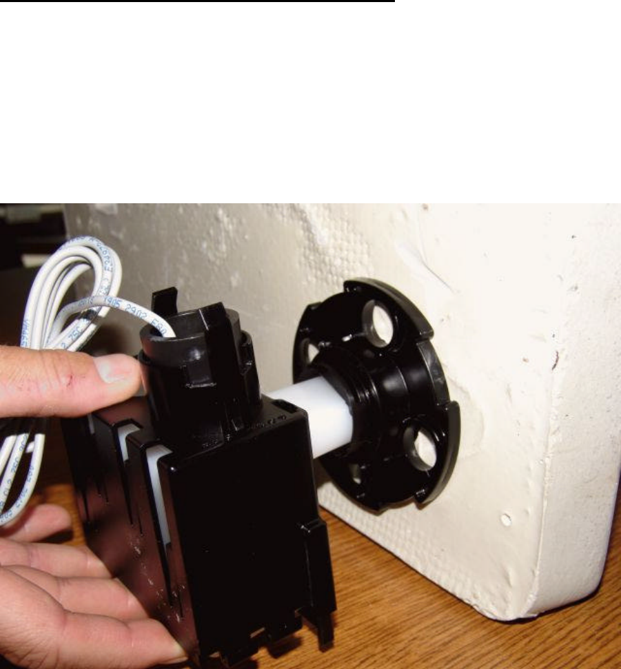
Step 4 Inserting the Radio Device in the Pit Lid Housing
1.) Insert the HDPE Radio with Boot into the cavity of the Pit Lid Housing
(See picture below)
2.) Align the Boot with the slot located on the bottom of the Pit Lid Housing to
secure the unit.
3.) To lock the unit into place, push Boot Locking Clip (opposite of the tabs)
until tabs are engaged and locked.
The endpoint is then inserted into the Pit Lid Housing:
Insertion of the Endpoint into the Pit Lid Housing
8
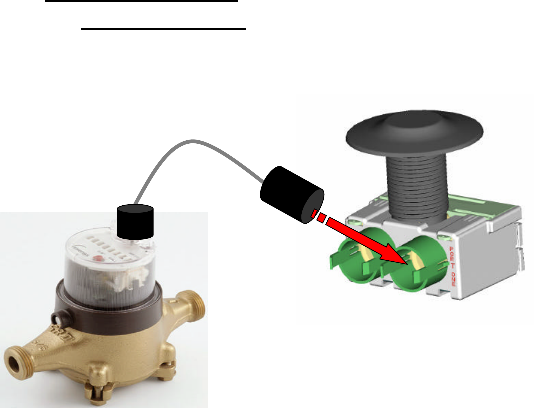
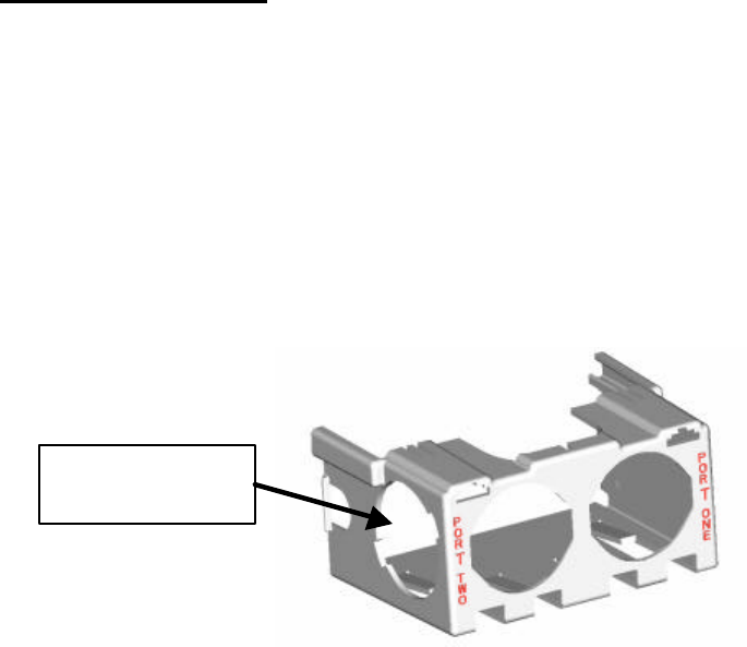
Step 5 Connecting meters to the radio
TouchCoupler (Sensus Only)
1.) Grasp the TRPL housing and place into Port 1 of the TouchCoupler
TR/PL Adaptor until secured. (See picture below)
2.) Repeat process into Port 2 if needed.

9
Wired Units (Sensus, MultiRead Module (RadioRead Only), Neptune)
Sensus Encoder
1.) Gel cap the red wire from the encoder to the red wire on the
reading port (either port 1 or port 2 – if available).
2.) Gel cap the green wire from the encoder to the green wire on
the reading port.
3.) Gel cap the black wire from the encoder to the black wire on the
reading port.
MultiRead Module
1.) Gel cap encoders to the MultiRead Module per the instructions
sheet for the MultiRead Module (AMR-306).
2.) Once all encoders are connected to the MultiRead Module, gel
cap the red wire from the MultiRead Module to the red wire on
the reading port (either port 1 or port 2 – if available).
3.) Gel cap the green wire from the MultiRead Module to the green
wire on the reading port.
4.) Gel cap the black wire from the MultiRead Module to the black
wire on the reading port.
Neptune Encoder
1.) Gel cap the red wire from the Neptune encoder to the green
wire on the reading port (either port 1 or port 2 – if available).
2.) Gel cap the green wire from the Neptune encoder to the black
wire on the reading port.
3.) Gel cap the black wire from the Neptune encoder to the red wire
on the reading port.
10
Step 6 Activate Radio
Note: if no meters are connected to this radio, the radio will not activate.
1.) Once all meters are connected, the radio must be activated in order for
it to perform its function. To activate, using a TouchReader or Model
4090 AutoGun, attempt a TouchRead on the Programming/TouchRead
port (See picture below). Once TouchRead is activated, the radio will
determine what is connected to this unit automatically. This may take
up to 3-6 seconds depending on if this unit is dual port capable and
what encoders are connected to it.
TouchReader
2.) The TouchReader will beep once indicating that the radio
acknowledged the TouchRead and is now detecting what is connected.
3.) After waiting ~3 seconds, attempt another TouchRead, if a read error
occurs, the radio is still in detect mode. Repeat this step again in 3
more seconds.
4.) If successful detection, it should provide either a TouchRead reading
(Sensus only) or a single beep to indicate that the encoder is
connected but TouchRead is not supported via the radio.
5.) If detection is unsuccessful, the TouchRead will beep once and restart
the activation similar to step 2 above.
AutoGun
(ID type set to Factory ID – see AutoGun manual for instructions)
2.) The AutoGun will beep and display for the ID “MXUGPTC0”. This
indicates that the radio acknowledged the TouchRead is in mode “0”
which is inactive. This will start the detecting process.
3.) After waiting ~3 seconds, attempt another TouchRead, if a read error
occurs, the radio is still in detect mode. Repeat this step again in 3
more seconds.
4.) If successful detection, the AutoGun will display either a TouchRead
reading (Sensus only) or
Programming /
TouchRead Port
11
• ID: MXUGPTC1 – which means a TouchRead was
attempted on an unsupported meter (Neptune).
• ID: MXUGPTC2 – which means that the port was
configured for a meter type that supports TouchRead
(Sensus only) but there was no response from the meter.
5.) If unsuccessful detection, the TouchRead will start the activation
process again. The ID on the AutoGun will display MXUGPTC0 similar
to the step 2 above.
Note: Once the radio is activated and it detected what is connected, the
only way to change its configuration as to what is connected is to
deactivate the radio using a programming tool and re-activate the radio or
use a programming tool to reprogram the port manually.
Warning… Programming a port manually will not allow the unit to perform
an automatic detection on that port unless reset to “AutoDetect”. The
activation process will not reset the port type.
12
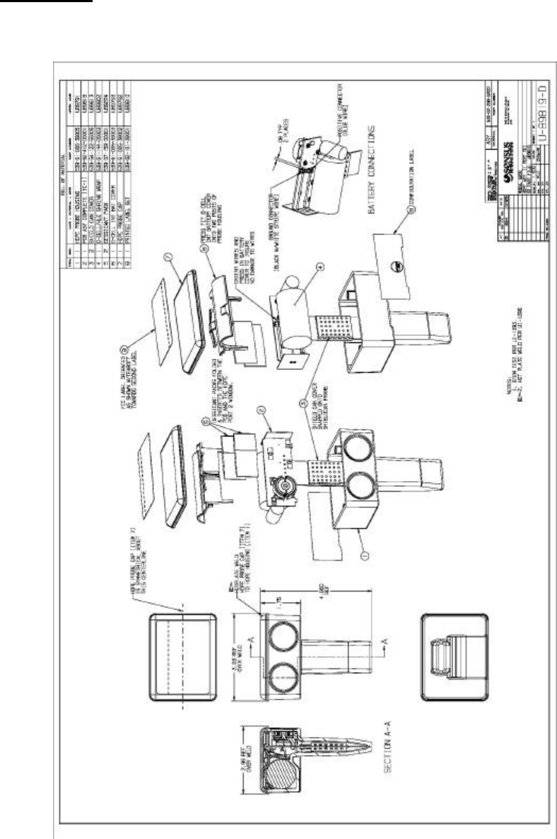
Appendix A:
The following drawings show how the PCB is oriented and installed into an enclosure.
13

12
Appendix B: Regulatory Information
FCC Information to User:
Changes or modifications not expressly approved by Sensus Metering Systems
could void the user's authority to operate the equipment.
In order to meet FCC’s RF exposure limits in section 1.1307 of the Rules, a minimum
separation of 20 cm must be maintained between the antenna of this device. The
antenna(s) used for this transmitter must not be co-located or operating in conjunction
with any other antenna or transmitter.