Sensus Metering Systems 520R 900MHz DTS RF Module User Manual Model 510R User Draft
Sensus Metering Systems 900MHz DTS RF Module Model 510R User Draft
Contents
- 1. Users Manual 510R
- 2. User Manual 520R
Users Manual 510R

Model 510 Installation Instructions
2
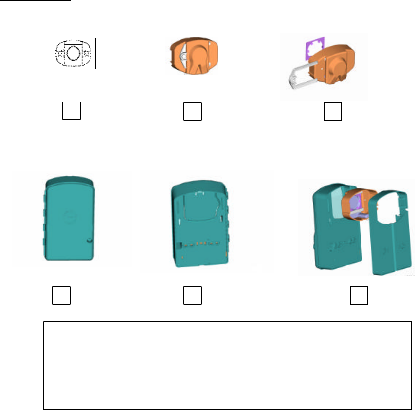
Definitions
1
–
Sensus TouchPad
2 – TouchPad Cover
3 – TouchPad Cover, Tinnerman Type Fastener, TouchPad Locking Clip
4 – Model 510 Radio (Front View)
5 – Model 510 Radio (Rear View with knockout)
6 – Model 510 Radio and TouchCoupler Spacer with TouchPad Cover
1
2
3
4
5
6

3
Table of Contents
Single Port – TouchCoupler Installation ____________________________________ 4
Dual Port – TouchCoupler Installation _____________________________________ 5
Single and Dual Port – Wired Installation___________________________________ 6
Activate Radio__________________________________________________________ 7
Appendix A: ___________________________________________________________ 9
Appendix B: Regulatory Information_____________________________________ 12
4
Single Port – TouchCoupler Installation
1) While Model 510 Radio and TouchCoupler Spacer with TouchPad Cover all
still assembled, align the TouchPad Cover over the Sensus TouchPad that is
secured to the wall and press on whole assembly.
2) For additional support, open Model 510 Radio door and screw two screws
using the holes located above the battery compartment.
3) Once secured, activate unit (see activation section).
5
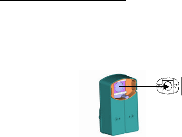
Dual Port – TouchCoupler Installation
1. First choose which Sensus TouchPad will be covered remotely. Place the remote
the TouchPad Cover over the Sensus TouchPad.
2. While Model 510 Radio and TouchCoupler Spacer with TouchPad Cover all still
assembled, align the TouchPad Cover over the Sensus TouchPad that is secured to
the wall and press on whole assembly.
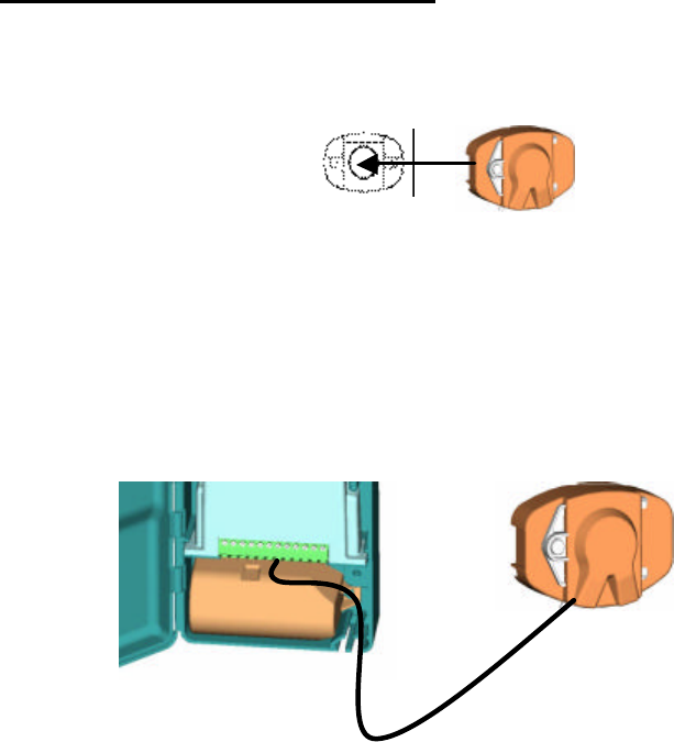
3. For additional support, open Model 510 Radio door and screw two screws using
the holes located above the battery compartment.
4. With the door still open, run the wire from the remote TouchPad Cover through
the bottom of the Model 510 Radio and attach to appropriate terminal screws.
5. Once all connections are complete, activate unit (see activation section).
6
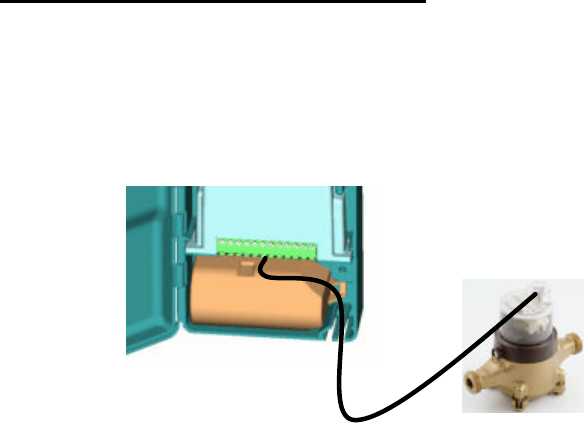
Single and Dual Port – Wired Installation
1. Open Model 510 Radio door.
2. Secure Model 510 Radio to a wall utilizing the screw holes above the battery
compartment.
3. Run the register wires through the bottom of the Model 510 Radio and connect to
the appropriate terminals.
4. Once all registers are connected, activate unit (see activation section).
7
Activate Radio
Note: if no meters are connected to this radio, the radio will not activate.
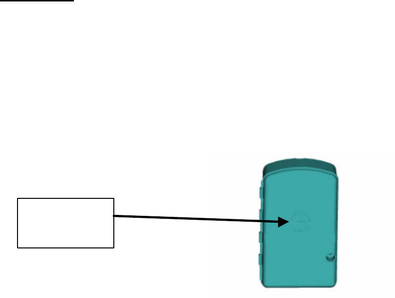
1.) Once all meters are connected, the radio must be activated in order for
it to perform its function. To activate, using a TouchReader or Model
4090 AutoGun, attempt a TouchRead on the Programming/TouchRead
port (See picture below). Once TouchRead is activated, the radio will
determine what is connected to this unit automatically. This may take
up to 3-6 seconds depending on if this unit is dual port capable and
what encoders are connected to it.
TouchReader
2.) The TouchReader will beep once indicating that the radio
acknowledged the TouchRead and is now detecting what is connected.
3.) After waiting ~3 seconds, attempt another TouchRead, if a read error
occurs, the radio is still in detect mode. Repeat this step again in 3
more seconds.
4.) If successful detection, it should provide either a TouchRead reading
(Sensus only) or a single beep to indicate that the encoder is
connected but TouchRead is not supported via the radio
5.) If detection is unsuccessful, the TouchRead will beep once and restart
the activation similar to step 2 above.
AutoGun
(ID type set to Factory ID – see AutoGun manual for instructions)
2.) The AutoGun will beep and display for the ID “MXUGPTC0”. This
indicates that the radio acknowledged the TouchRead is in mode “0”
which is inactive. This will start the detecting process.
3.) After waiting ~3 seconds, attempt another TouchRead, if a read error
occurs, the radio is still in detect mode. Repeat this step again in 3
more seconds.
4.) If successful detection, the AutoGun will display either a TouchRead
reading (Sensus only) or
Programming /
TouchRead Port
(Sensus Logo)
8
• ID: MXUGPTC1 – which means a TouchRead was
attempted on an unsupported meter (Neptune).
• ID: MXUGPTC2 – which means that the port was
configured for a meter type that supports TouchRead
(Sensus only) but there was no response from the meter.
5.) If unsuccessful detection, the TouchRead will start the activation
process again. The ID on the AutoGun will display MXUGPTC0 similar
to the step 2 above.
Note: Once the radio is activated and it detected what is connected, the
only way to change its configuration as to what is connected is to
deactivate the radio using a programming tool and re-activate the radio or
use a programming tool to reprogram the port manually.
Warning… Programming a port manually will not allow the unit to perform
an automatic detection on that port unless reset to “AutoDetect”. The
activation process will not reset the port type.
9
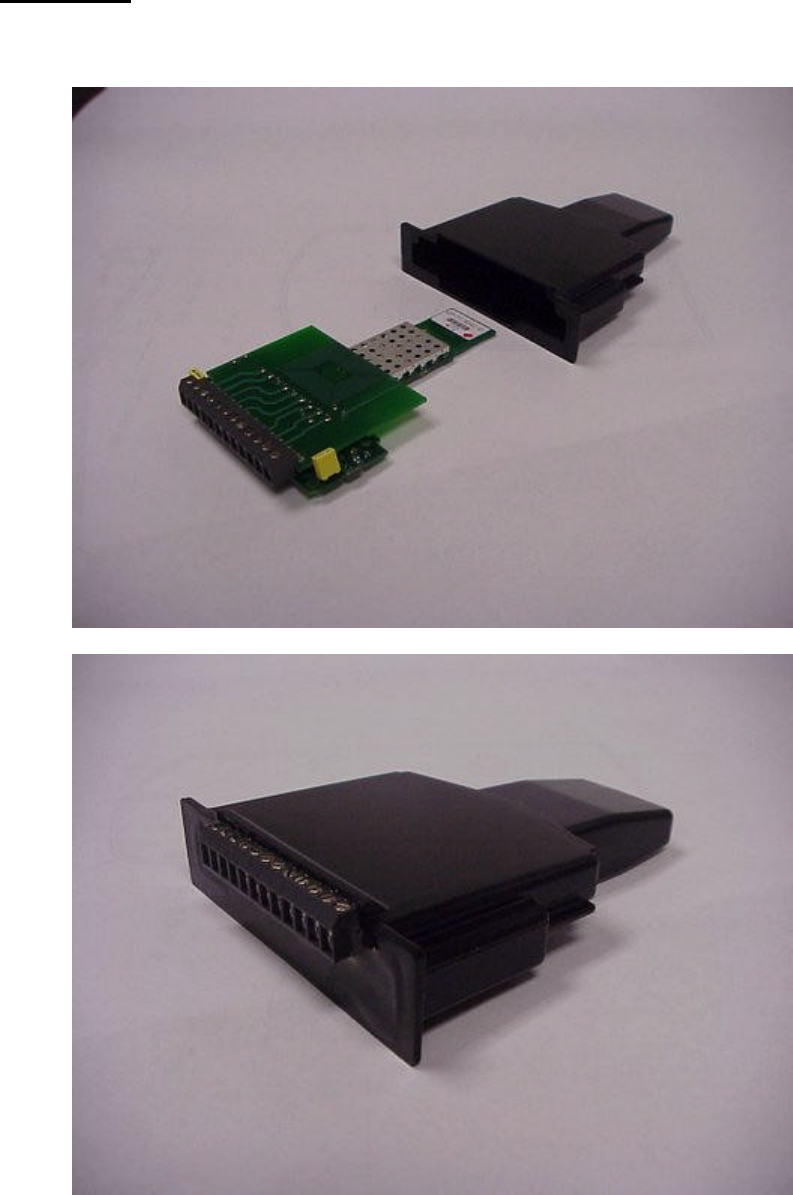
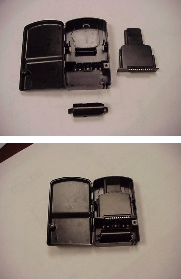
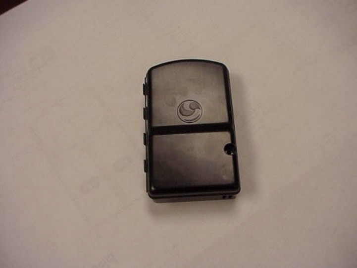
Appendix A:
The following photos show how the PCB is oriented and installed into an enclosure.
10
11

12
Appendix B: Regulatory Information
FCC Information to User:
Changes or modifications not expressly approved by Sensus Metering Systems
could void the user's authority to operate the equipment.
In order to meet FCC’s RF exposure limits in section 1.1307 of the Rules, a minimum
separation of 20 cm must be maintained between the antenna of this device. The
antenna(s) used for this transmitter must not be co-located or operating in conjunction
with any other antenna or transmitter.