Sensus Metering Systems BA0031 Network Base Station For Metering System User Manual BA0031 12 14 04
Sensus Metering Systems Network Base Station For Metering System BA0031 12 14 04
UserManual.wiki
>
Sensus Metering Systems
>
BA0031 User Manual
>
User Manual
Contents
1.
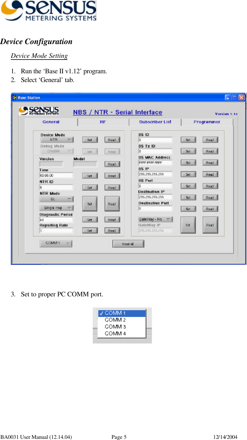
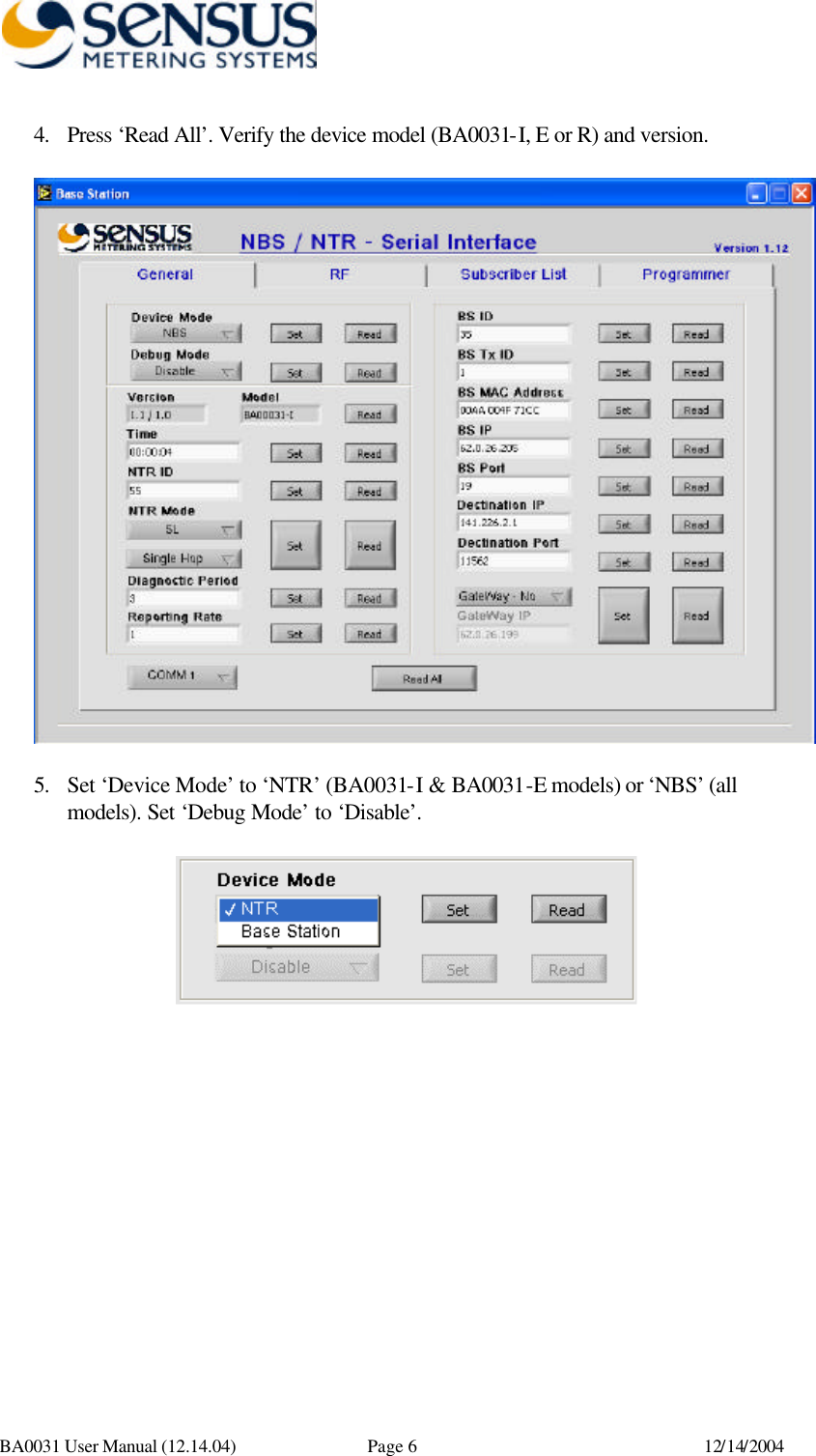
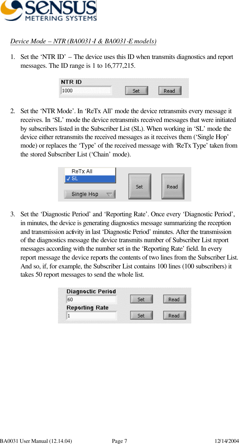
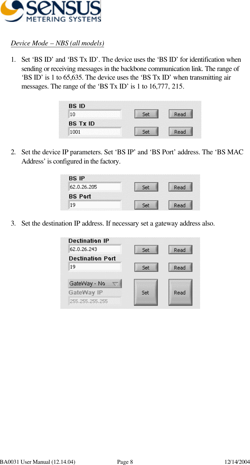
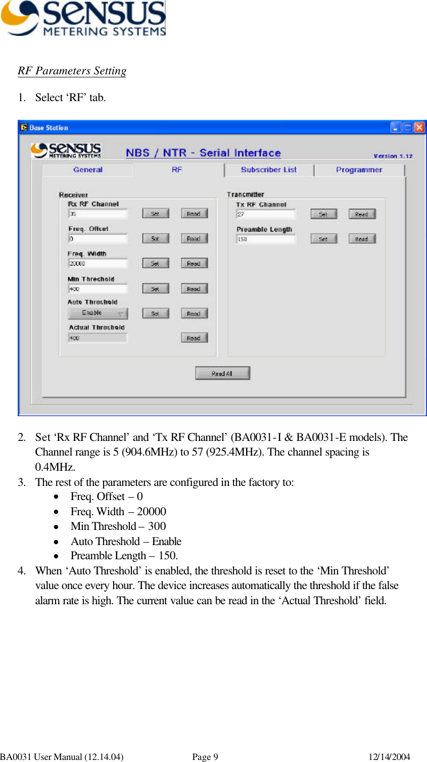
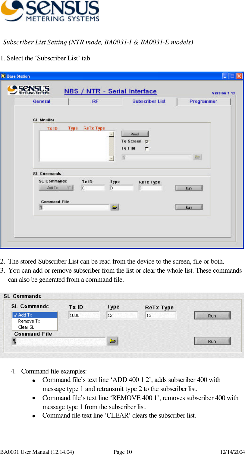
User Manual
2.
Installation Guide
User Manual
Navigation menu
Upload a User Manual
Namespaces
Wiki Guide
HTML
PDF
Info
Views
User Manual
Discussion / Help
Navigation