Sensus Metering Systems BA0031 Network Base Station For Metering System User Manual Installation Guide
Sensus Metering Systems Network Base Station For Metering System Installation Guide
Contents
- 1. User Manual
- 2. Installation Guide
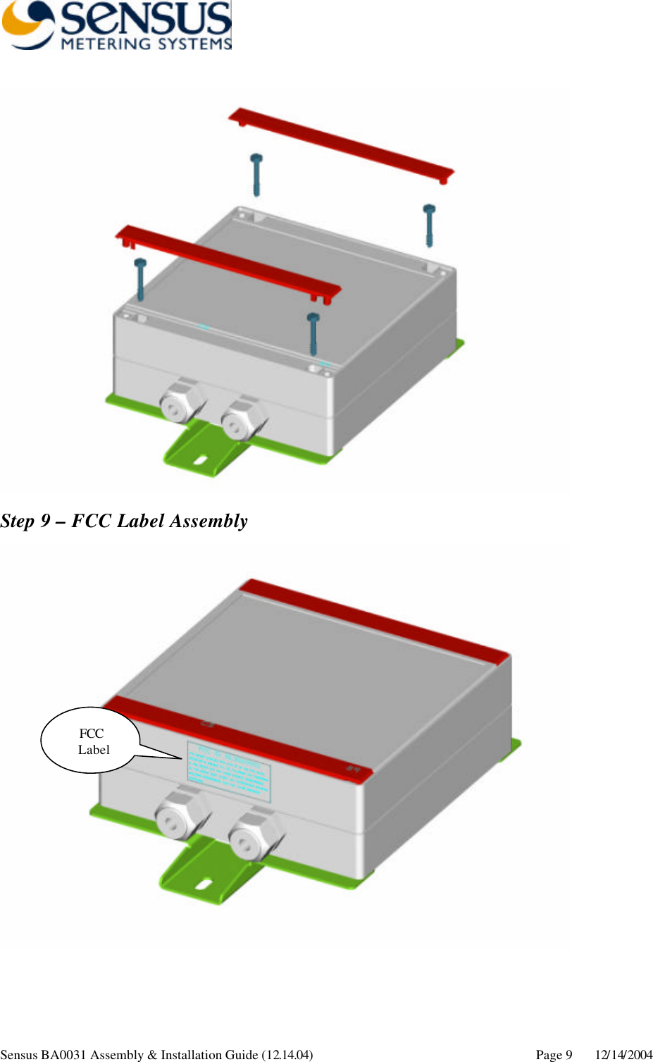
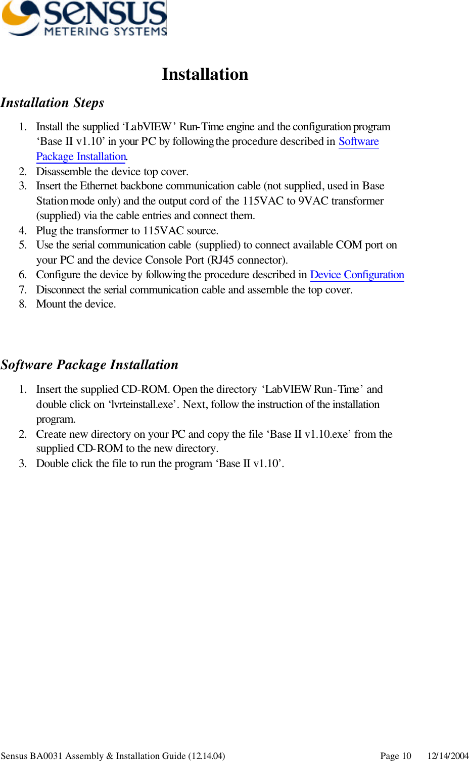
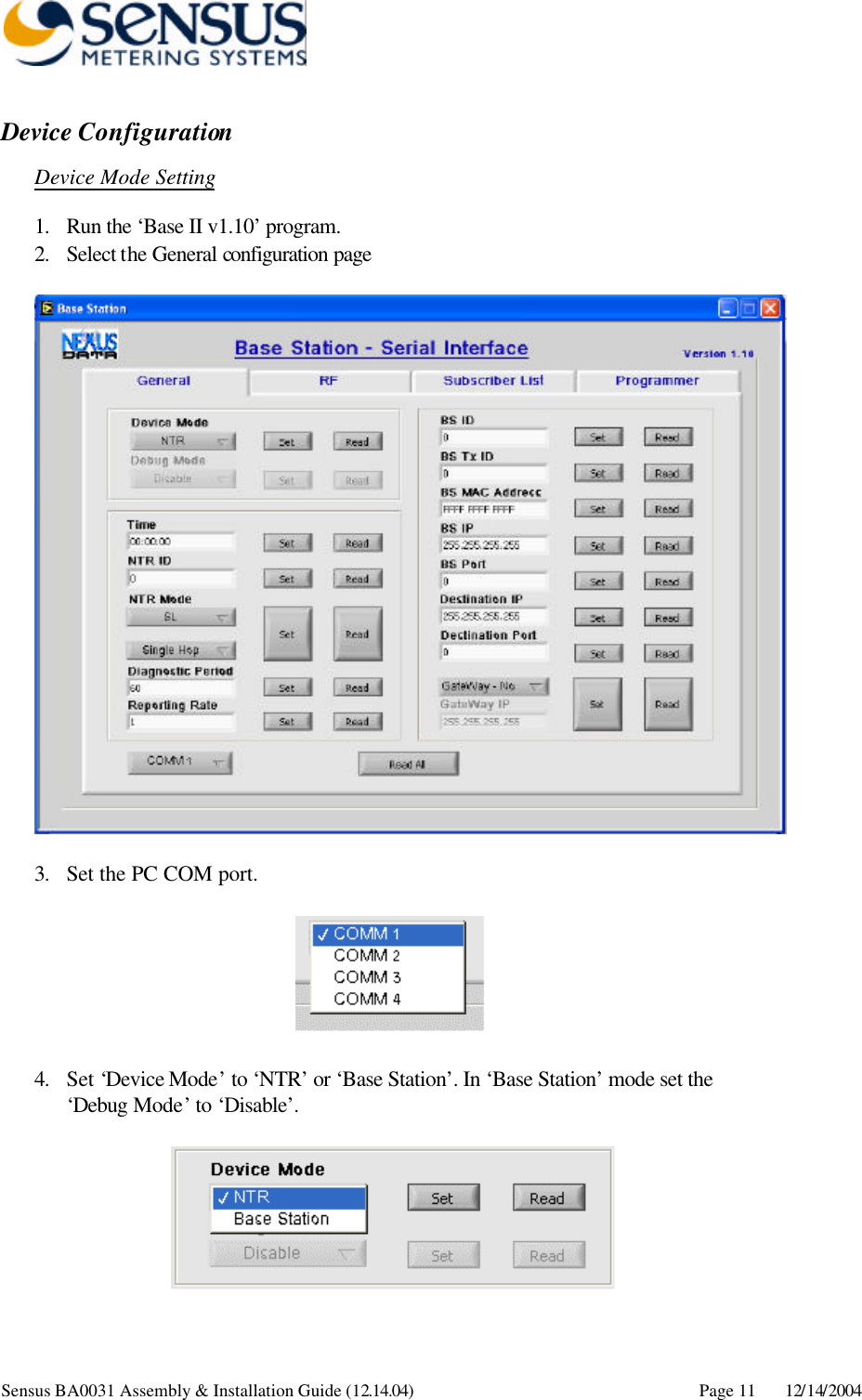
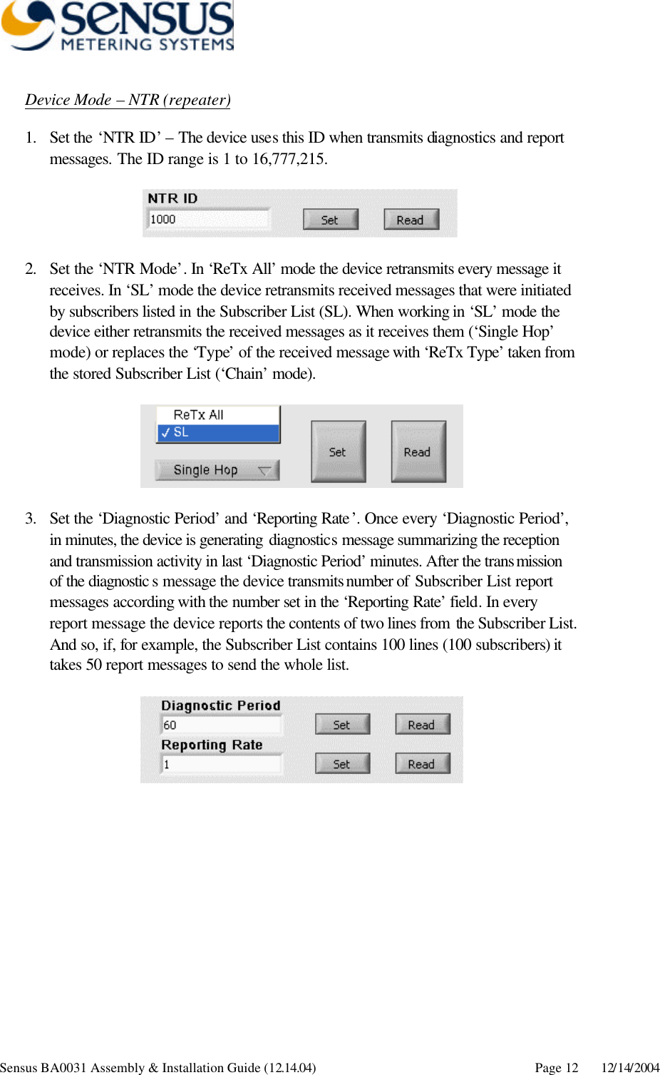
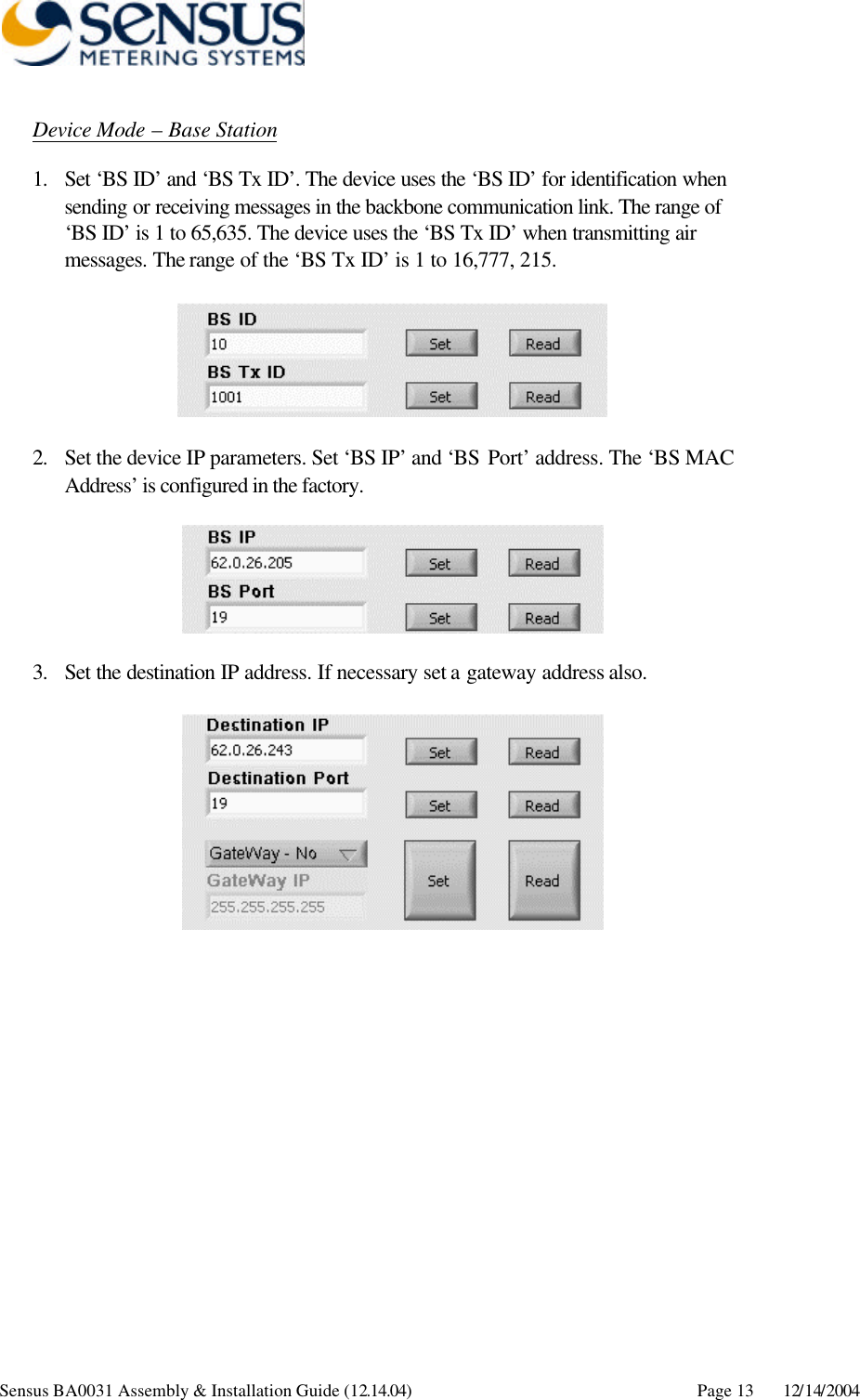
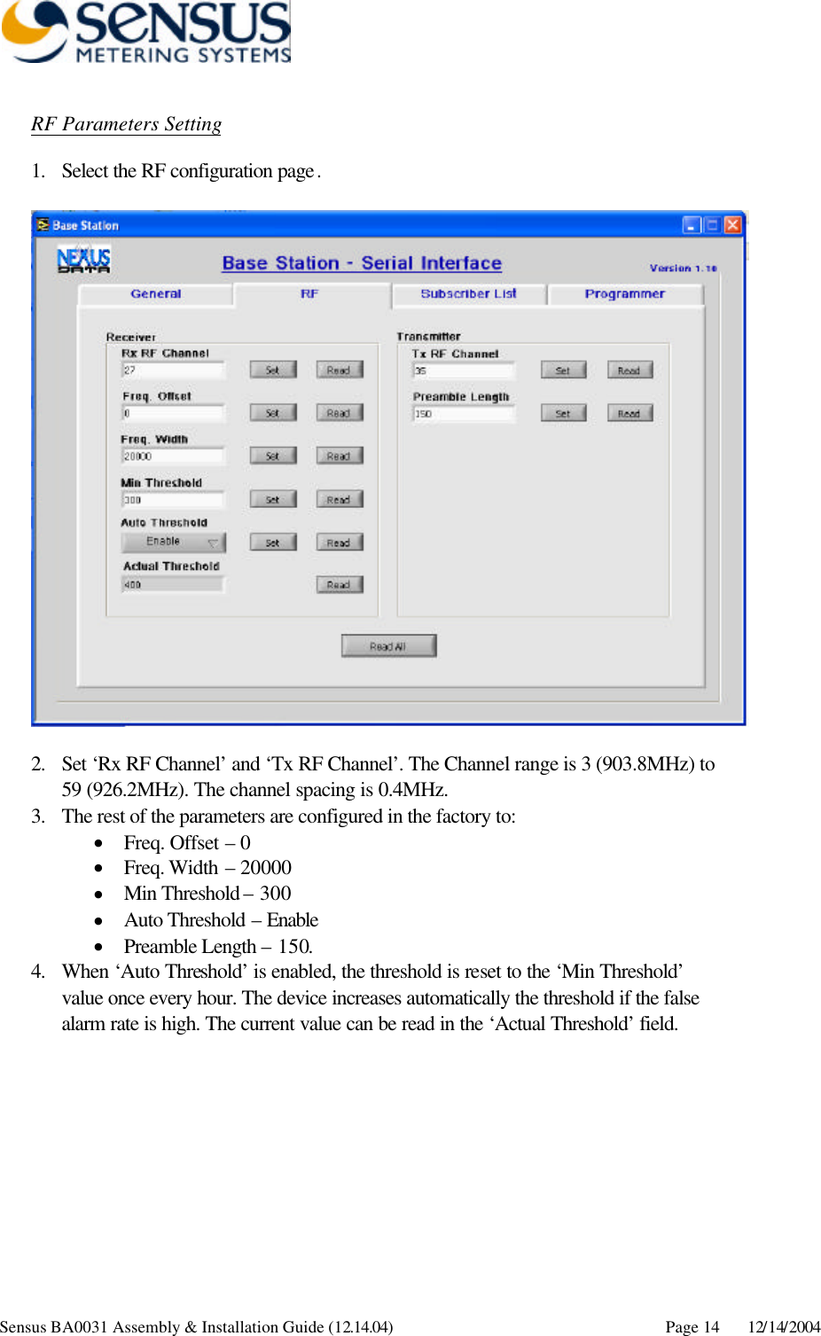
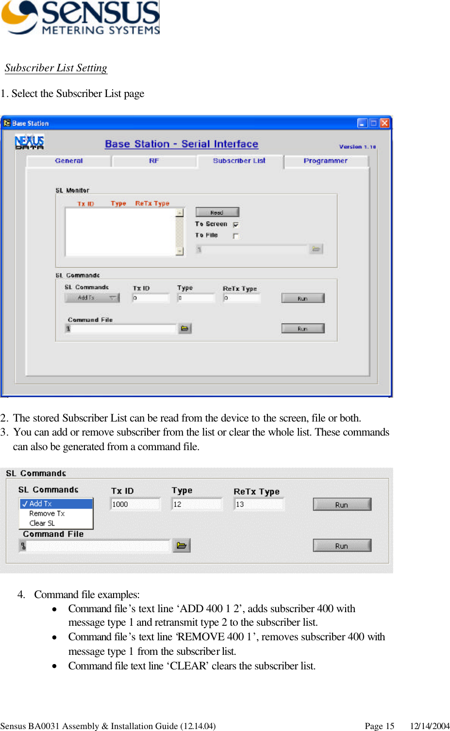
Installation Guide