Sensus Metering Systems BA0031 Network Base Station For Metering System User Manual Installation Guide
Sensus Metering Systems Network Base Station For Metering System Installation Guide
Contents
- 1. User Manual
- 2. Installation Guide
Installation Guide

Network Base Station
BA0031-A
Mechanical Assembly and Installation
Guide

Sensus BA0031 Assembly & Installation Guide (12.14.04) Page 2 12/14/2004
Table of Contents
FCC Warning .....................................................................................3
Box Assembly ....................................................................................4
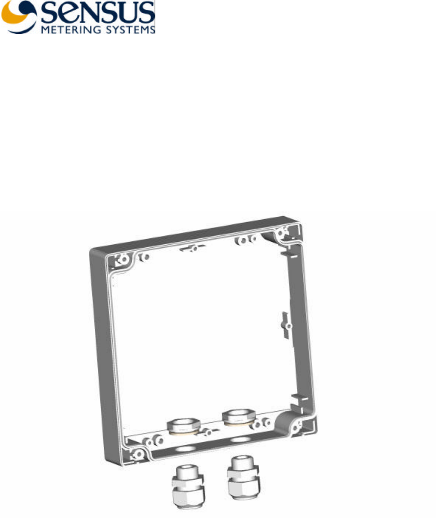
Step 1 – Cable Entries Assembly.......................................................4
Step 2 – Bottom Plate Assembly.......................................................5
Step 3 – Board Standoffs Assembly..................................................5
Step 4 – Board Assembly .................................................................6
Step 5 – Shield Assembly .................................................................7
Step 6 – Internal Antenna Assembly ..................................................7
Step 7 – Brackets Assembly .............................................................8
Step 8 – Top Cover Assembly ..........................................................8
Step 9 – FCC Label Assembly ..........................................................9
Installation........................................................................................10
Installation Steps ............................................................................10
Software Package Installation..........................................................10
Device Configuration......................................................................11
Device Mode Setting....................................................................11
Device Mode – NTR (repeater) ....................................................12
Device Mode – Base Station........................................................13
RF Parameters Setting..................................................................14
Subscriber List Setting .................................................................15

Sensus BA0031 Assembly & Installation Guide (12.14.04) Page 3 12/14/2004
FCC Warning
FCC Warning
Modifications not expressly approved by the manufacturer
could void the user authority to operate the equipment under
FCC Rules.
To comply with FCC RF Exposure requirements, the antenna(s)
used for this transmitter must be fixed-mounted on outdoor
permanent structures with a separation distance of at least 2
meters from all persons and must not be co-located or operating
in conjunction with any other antenna or transmitter.
Installation of BA0031 NTR:
Installation of Model BA0031 and associated antennae (internal
and external) must be performed by trained professionals only.
The following antennae (or equivalent) should be used for the
various BA0031 models.
BA0031-I: Antenna Model – Internal Patch (Sensus Drawing
Number 7300574), (4dBi)
BA0031-E: Amphenol Antel BCD-8243 (5.15dBi Omni)
BA0031-R: Amphenol Antel BCD-87066 (8.15dBi Omni)
Sensus BA0031 Assembly & Installation Guide (12.14.04) Page 4 12/14/2004
Box Assembly
Step 1 – Cable Entries Assembly
Sensus BA0031 Assembly & Installation Guide (12.14.04) Page 5 12/14/2004
Step 2 – Bottom Plate Assembly
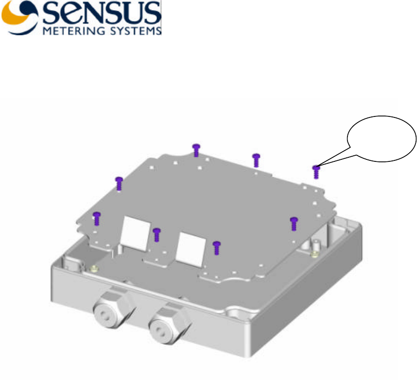
Step 3 – Board Standoffs Assembly
8 screws
Ejot 30x8
Sensus BA0031 Assembly & Installation Guide (12.14.04) Page 6 12/14/2004
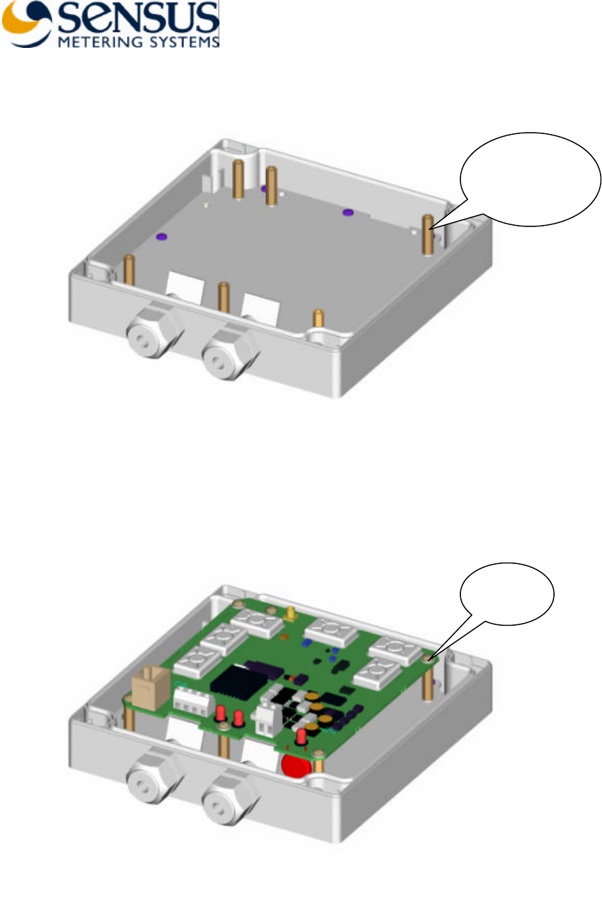
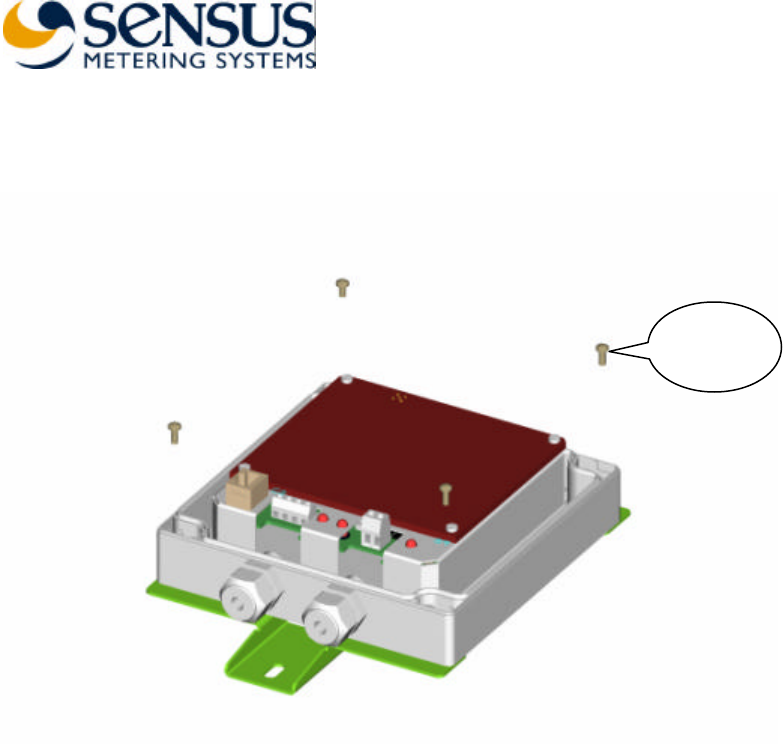
Step 4 – Board Assembly
6 screws
M3x6
6 standoffs
M3x2 1 and
spring washer
M3
Sensus BA0031 Assembly & Installation Guide (12.14.04) Page 7 12/14/2004
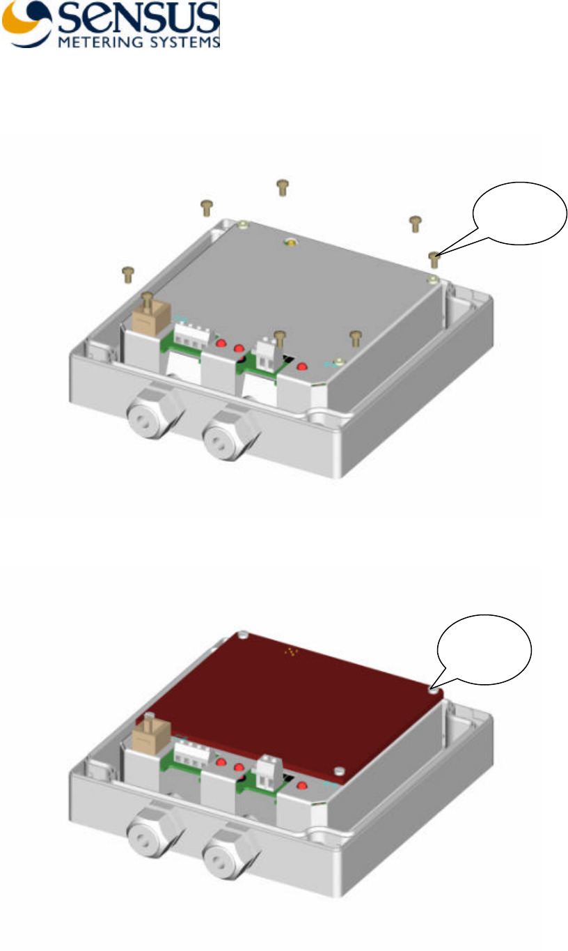
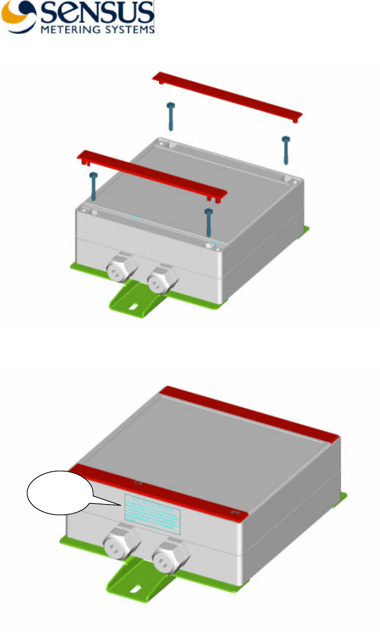
Step 5 – Shield Assembly
Step 6 – Internal Antenna Assembly
4 plastic
screws
M3x8
8 screws
M3x6
Sensus BA0031 Assembly & Installation Guide (12.14.04) Page 8 12/14/2004
Step 7 – Brackets Assembly
Step 8 – Top Cover Assembly
4 screws
M3x8
Sensus BA0031 Assembly & Installation Guide (12.14.04) Page 9 12/14/2004
Step 9 – FCC Label Assembly
FCC
Label

Sensus BA0031 Assembly & Installation Guide (12.14.04) Page 10 12/14/2004
Installation
Installation Steps
1. Install the supplied ‘LabVIEW’ Run-Time engine and the configuration program
‘Base II v1.10’ in your PC by following the procedure described in Software
Package Installation.
2. Disassemble the device top cover.
3. Insert the Ethernet backbone communication cable (not supplied, used in Base
Station mode only) and the output cord of the 115VAC to 9VAC transformer
(supplied) via the cable entries and connect them.
4. Plug the transformer to 115VAC source.
5. Use the serial communication cable (supplied) to connect available COM port on
your PC and the device Console Port (RJ45 connector).
6. Configure the device by following the procedure described in Device Configuration
7. Disconnect the serial communication cable and assemble the top cover.
8. Mount the device.
Software Package Installation
1. Insert the supplied CD-ROM. Open the directory ‘LabVIEW Run-Time’ and
double click on ‘lvrteinstall.exe’. Next, follow the instruction of the installation
program.
2. Create new directory on your PC and copy the file ‘Base II v1.10.exe’ from the
supplied CD-ROM to the new directory.
3. Double click the file to run the program ‘Base II v1.10’.
Sensus BA0031 Assembly & Installation Guide (12.14.04) Page 11 12/14/2004
Device Configuration
Device Mode Setting
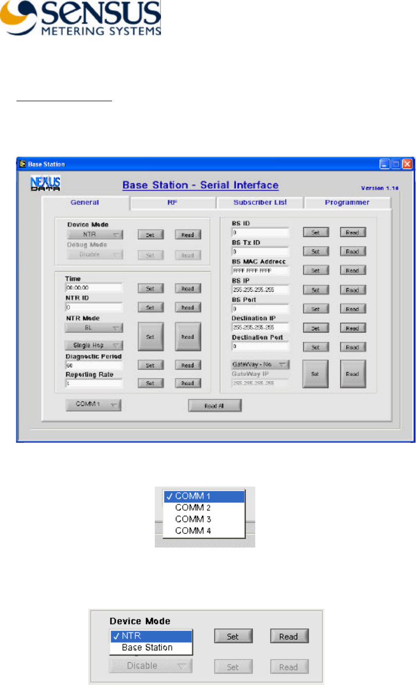
1. Run the ‘Base II v1.10’ program.
2. Select the General configuration page
3. Set the PC COM port.
4. Set ‘Device Mode’ to ‘NTR’ or ‘Base Station’. In ‘Base Station’ mode set the
‘Debug Mode’ to ‘Disable’.
Sensus BA0031 Assembly & Installation Guide (12.14.04) Page 12 12/14/2004
Device Mode – NTR (repeater)
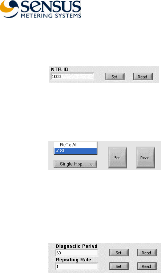
1. Set the ‘NTR ID’ – The device uses this ID when transmits diagnostics and report
messages. The ID range is 1 to 16,777,215.
2. Set the ‘NTR Mode’. In ‘ReTx All’ mode the device retransmits every message it
receives. In ‘SL’ mode the device retransmits received messages that were initiated
by subscribers listed in the Subscriber List (SL). When working in ‘SL’ mode the
device either retransmits the received messages as it receives them (‘Single Hop’
mode) or replaces the ‘Type’ of the received message with ‘ReTx Type’ taken from
the stored Subscriber List (‘Chain’ mode).
3. Set the ‘Diagnostic Period’ and ‘Reporting Rate’. Once every ‘Diagnostic Period’,
in minutes, the device is generating diagnostics message summarizing the reception
and transmission activity in last ‘Diagnostic Period’ minutes. After the transmission
of the diagnostic s message the device transmits number of Subscriber List report
messages according with the number set in the ‘Reporting Rate’ field. In every
report message the device reports the contents of two lines from the Subscriber List.
And so, if, for example, the Subscriber List contains 100 lines (100 subscribers) it
takes 50 report messages to send the whole list.
Sensus BA0031 Assembly & Installation Guide (12.14.04) Page 13 12/14/2004
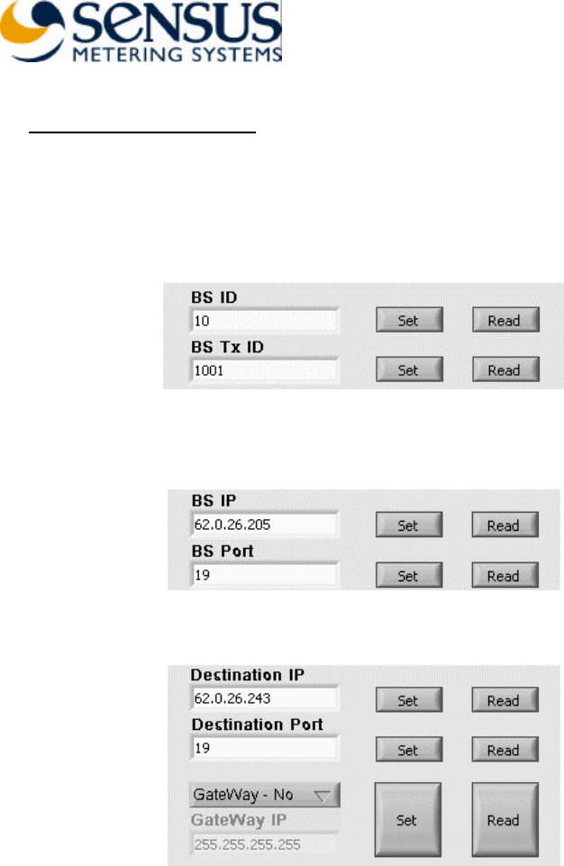
Device Mode – Base Station
1. Set ‘BS ID’ and ‘BS Tx ID’. The device uses the ‘BS ID’ for identification when
sending or receiving messages in the backbone communication link. The range of
‘BS ID’ is 1 to 65,635. The device uses the ‘BS Tx ID’ when transmitting air
messages. The range of the ‘BS Tx ID’ is 1 to 16,777, 215.
2. Set the device IP parameters. Set ‘BS IP’ and ‘BS Port’ address. The ‘BS MAC
Address’ is configured in the factory.
3. Set the destination IP address. If necessary set a gateway address also.
Sensus BA0031 Assembly & Installation Guide (12.14.04) Page 14 12/14/2004
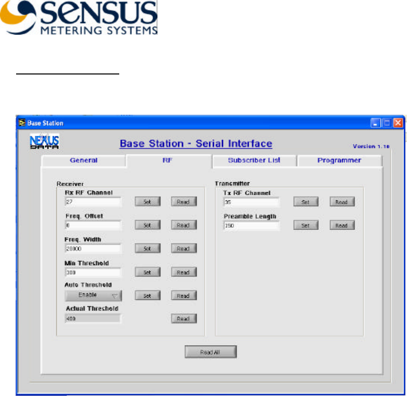
RF Parameters Setting
1. Select the RF configuration page.
2. Set ‘Rx RF Channel’ and ‘Tx RF Channel’. The Channel range is 3 (903.8MHz) to
59 (926.2MHz). The channel spacing is 0.4MHz.
3. The rest of the parameters are configured in the factory to:
• Freq. Offset – 0
• Freq. Width – 20000
• Min Threshold – 300
• Auto Threshold – Enable
• Preamble Length – 150.
4. When ‘Auto Threshold’ is enabled, the threshold is reset to the ‘Min Threshold’
value once every hour. The device increases automatically the threshold if the false
alarm rate is high. The current value can be read in the ‘Actual Threshold’ field.
Sensus BA0031 Assembly & Installation Guide (12.14.04) Page 15 12/14/2004
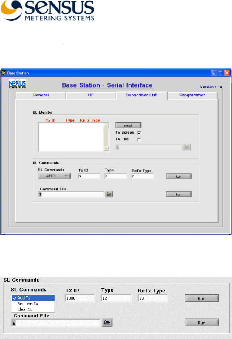
Subscriber List Setting
1. Select the Subscriber List page
2. The stored Subscriber List can be read from the device to the screen, file or both.
3. You can add or remove subscriber from the list or clear the whole list. These commands
can also be generated from a command file.
4. Command file examples:
• Command file’s text line ‘ADD 400 1 2’, adds subscriber 400 with
message type 1 and retransmit type 2 to the subscriber list.
• Command file’s text line ‘REMOVE 400 1’, removes subscriber 400 with
message type 1 from the subscriber list.
• Command file text line ‘CLEAR’ clears the subscriber list.

Sensus BA0031 Assembly & Installation Guide (12.14.04) Page 16 12/14/2004