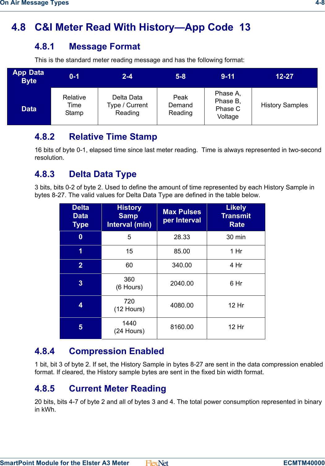
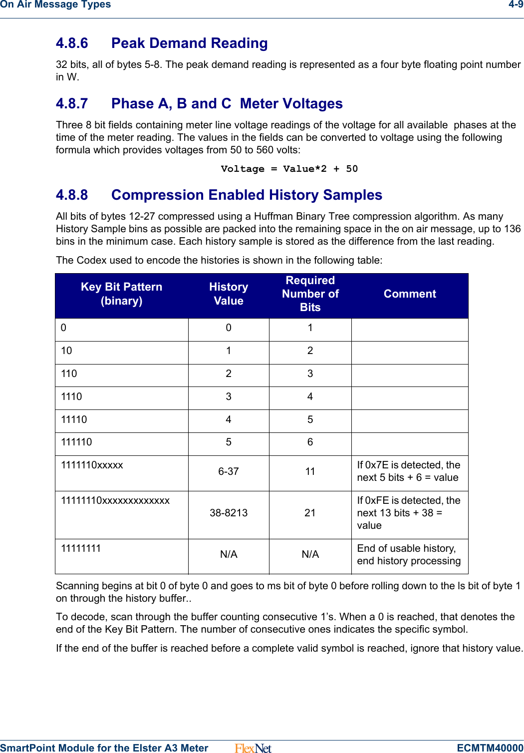
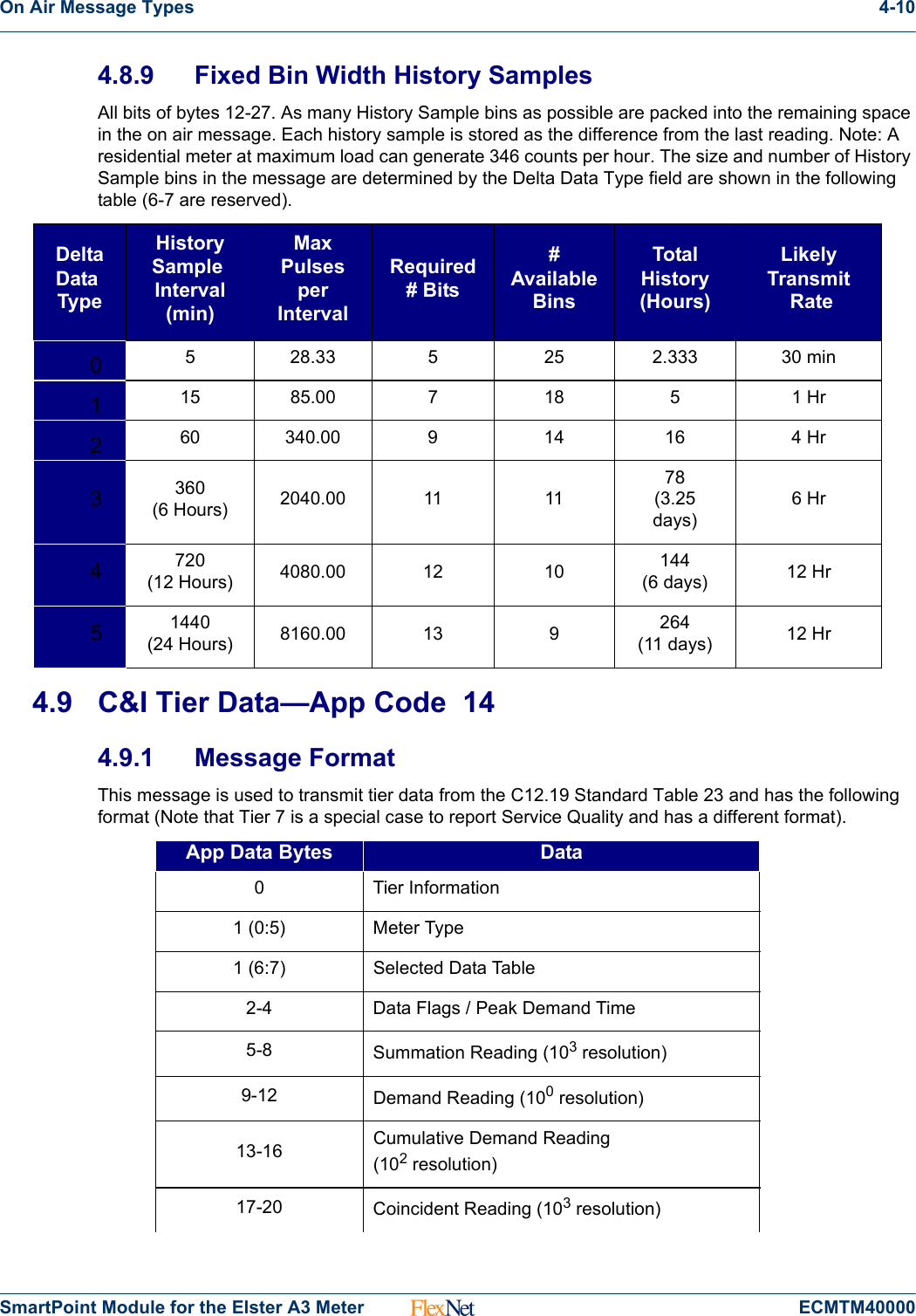
Sensus Metering Systems FLEXELS Radio Telemetry Module User Manual FlexNet Module for the Elster A3
Sensus Metering Systems Inc. Radio Telemetry Module FlexNet Module for the Elster A3
UserManual.wiki
>
Sensus Metering Systems
>
FLEXELS User Manual
Manual
Navigation menu
Upload a User Manual
Namespaces
Wiki Guide
HTML
PDF
Info
Views
User Manual
Discussion / Help
Navigation
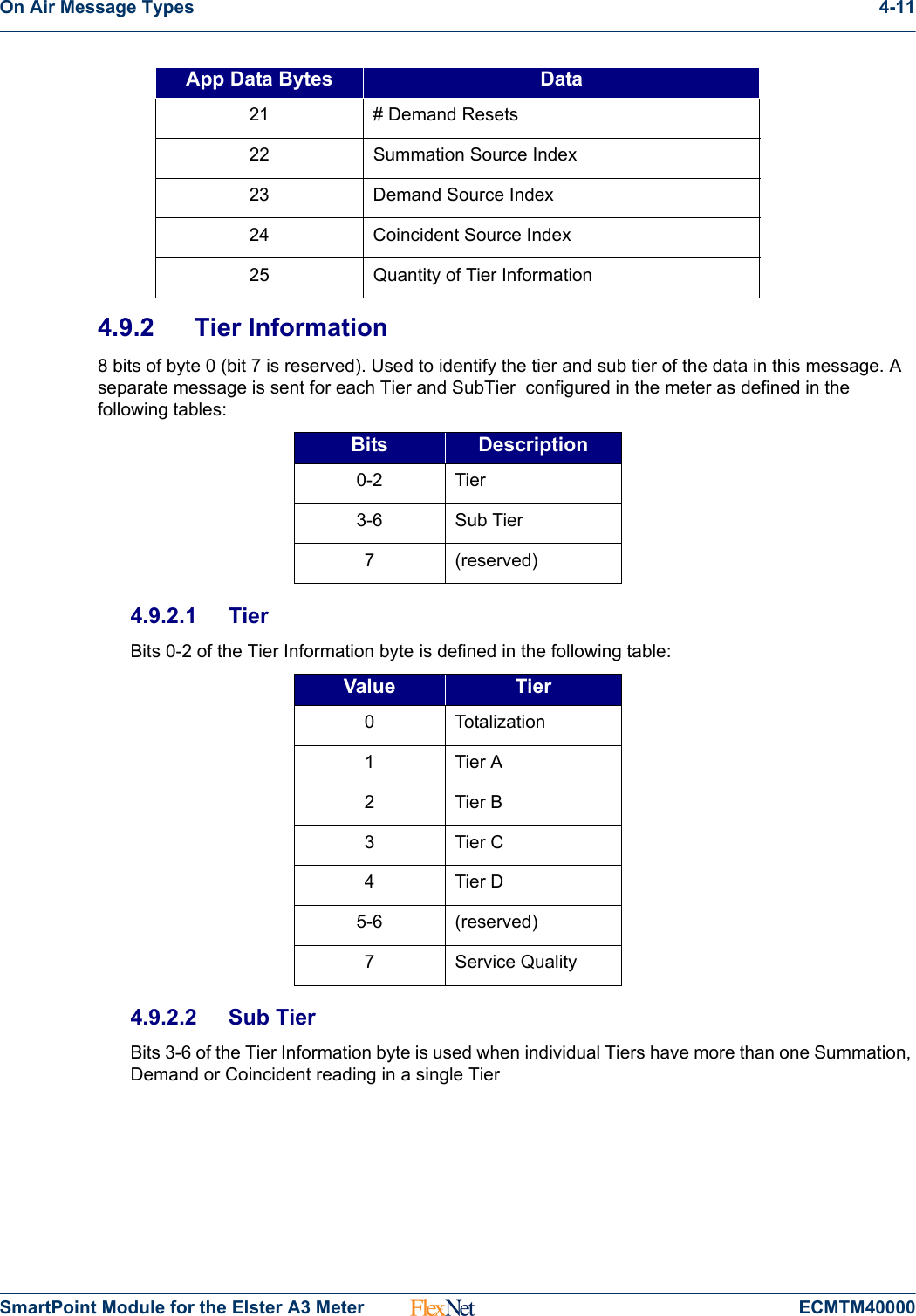
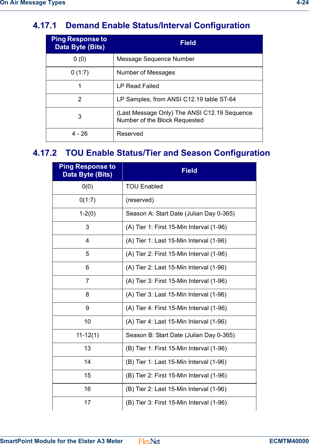
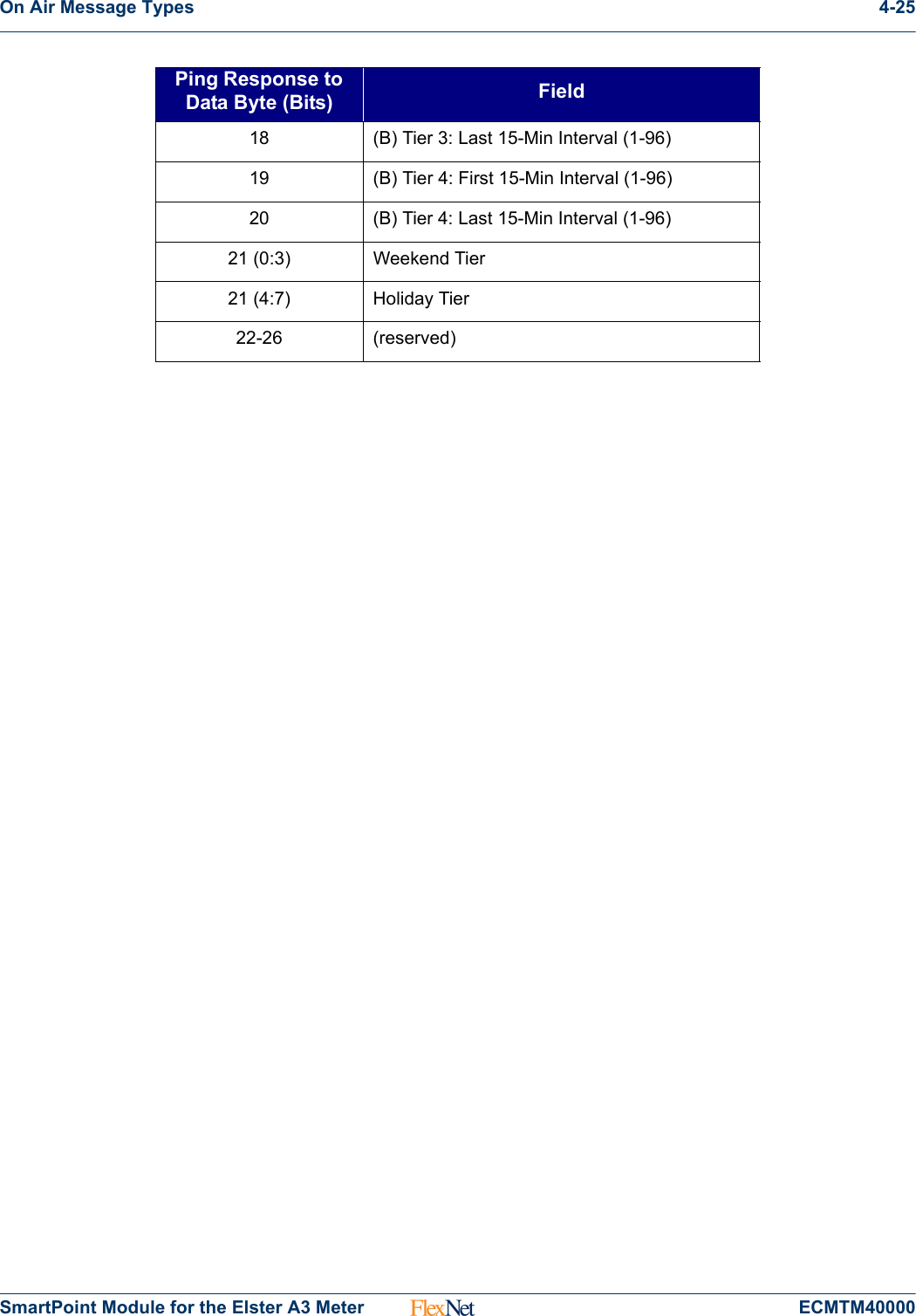
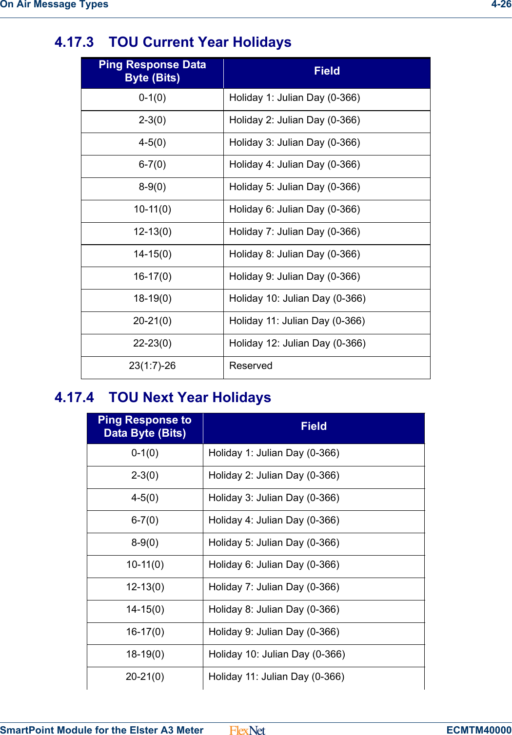
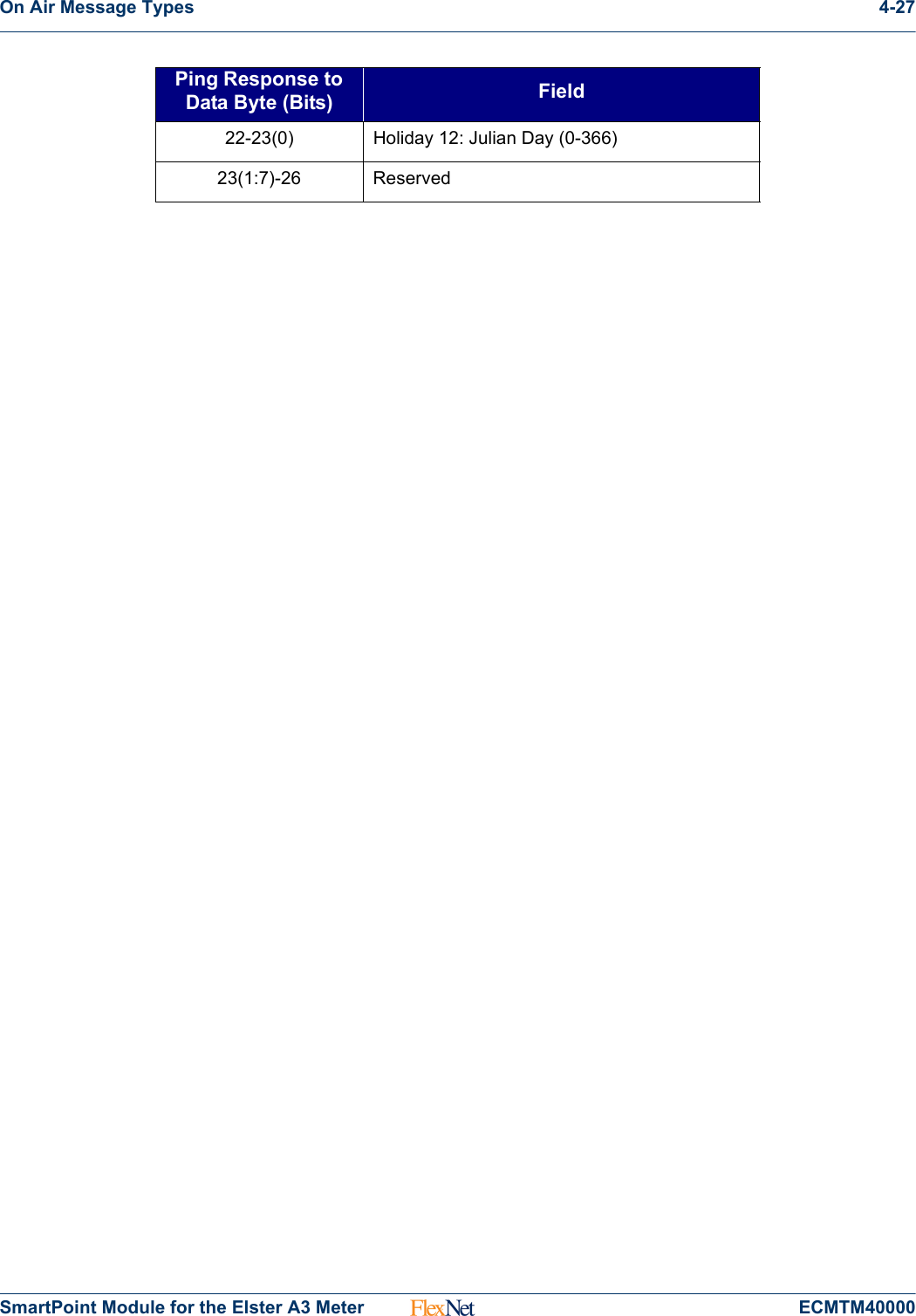
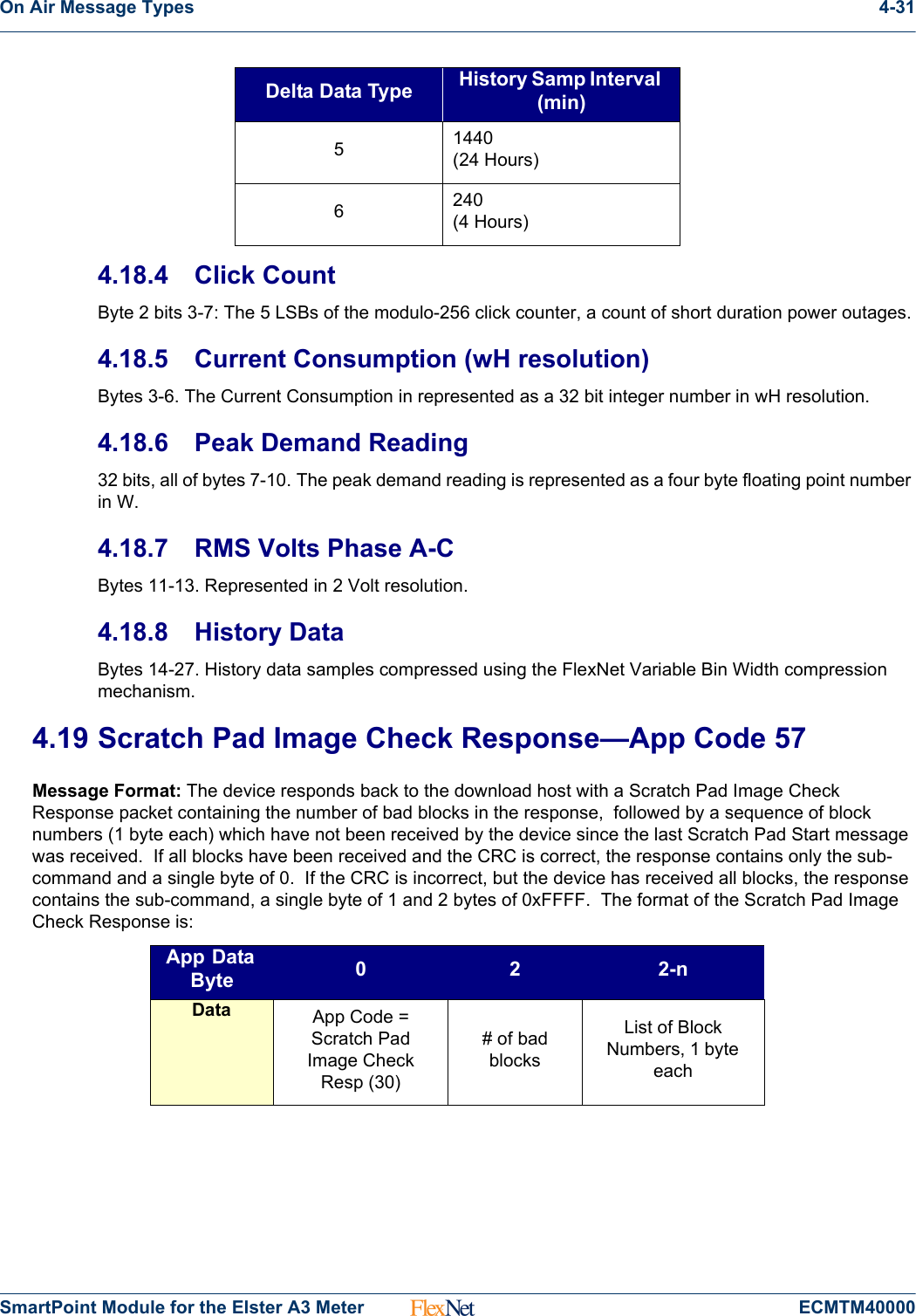
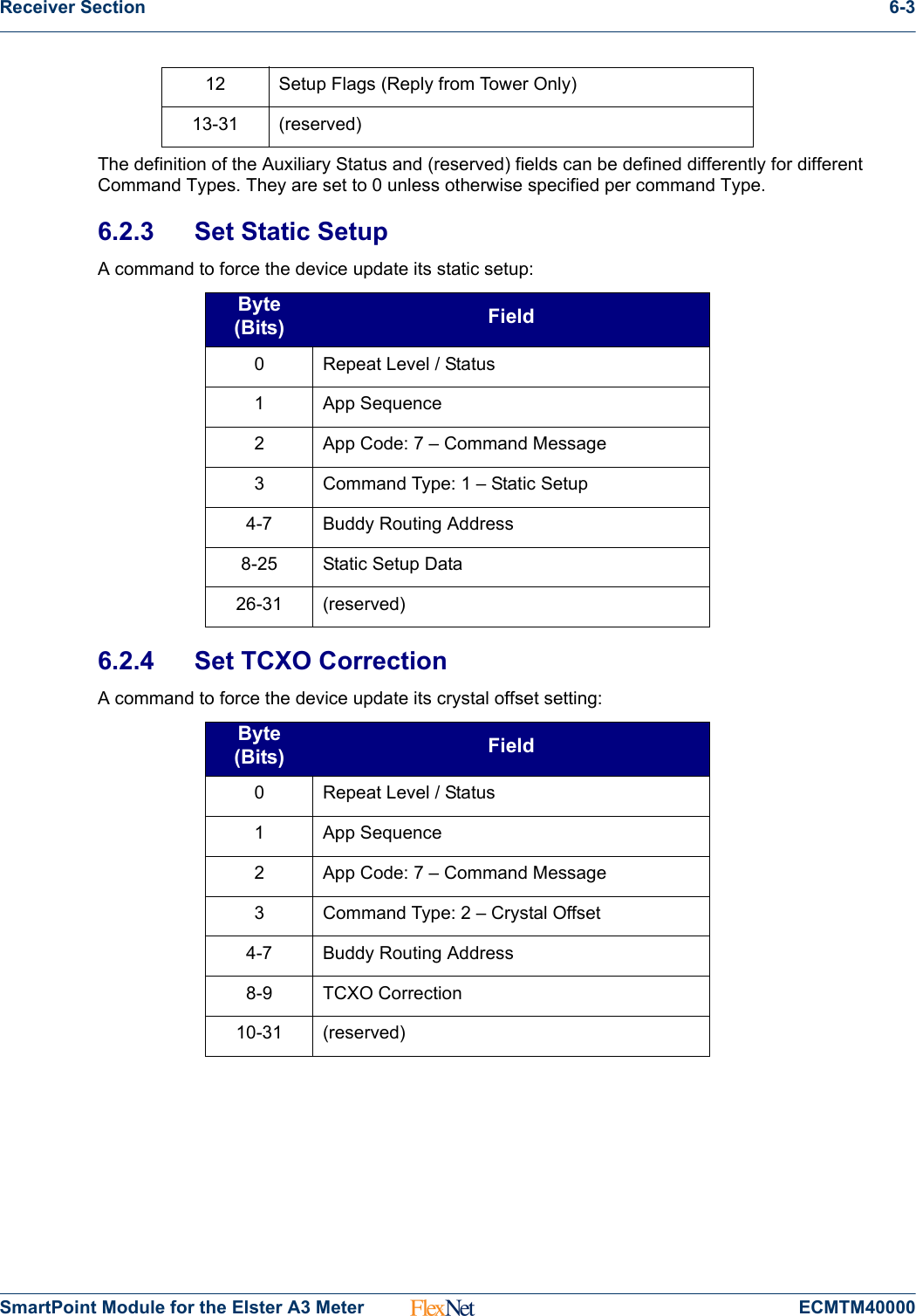
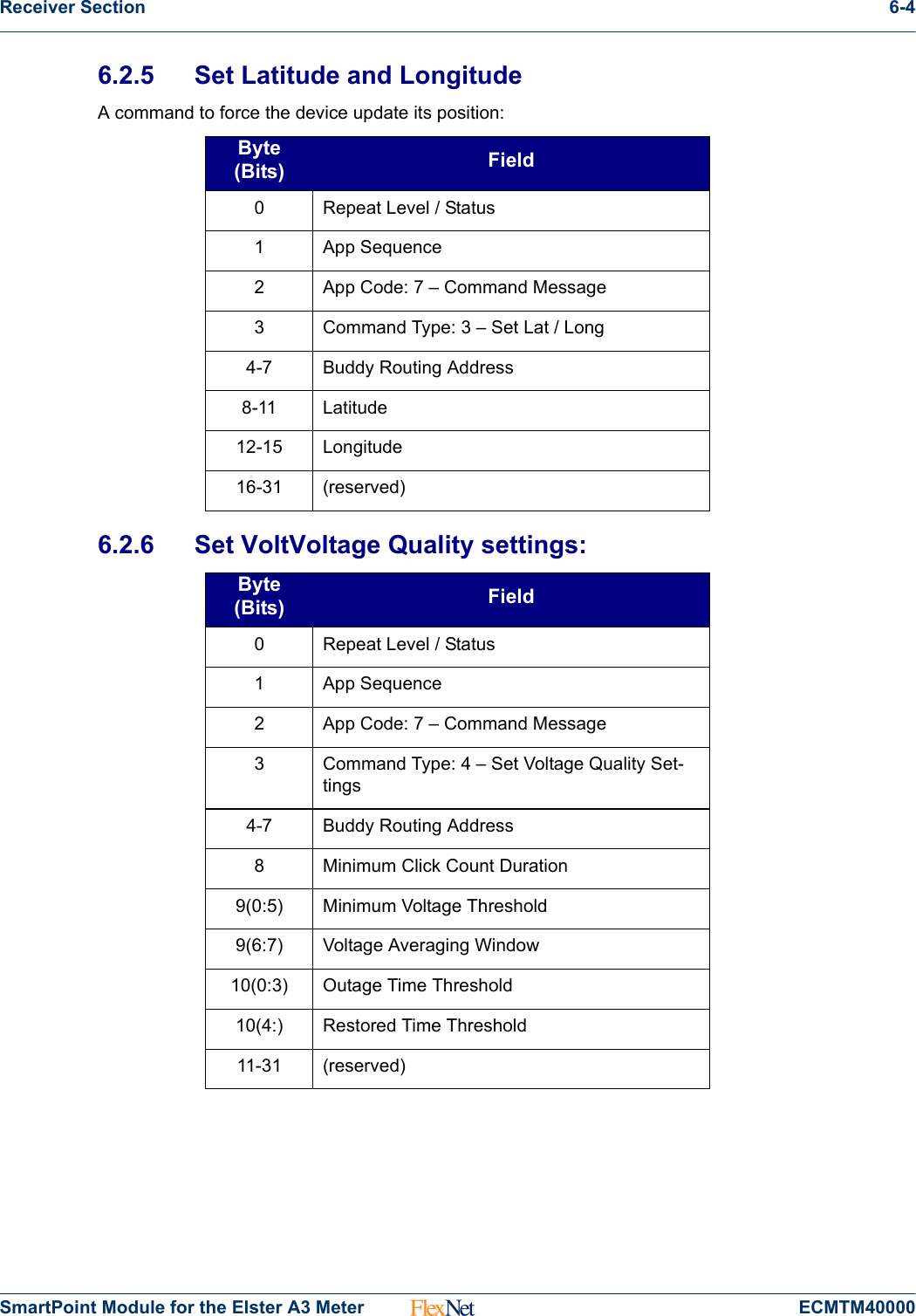
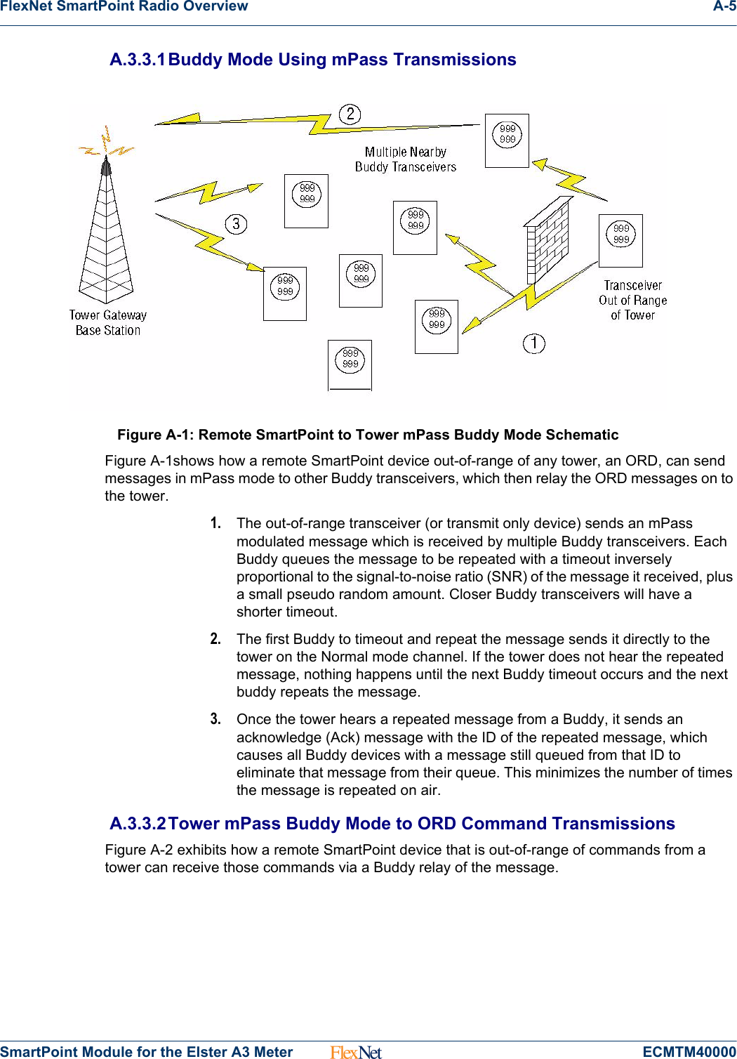
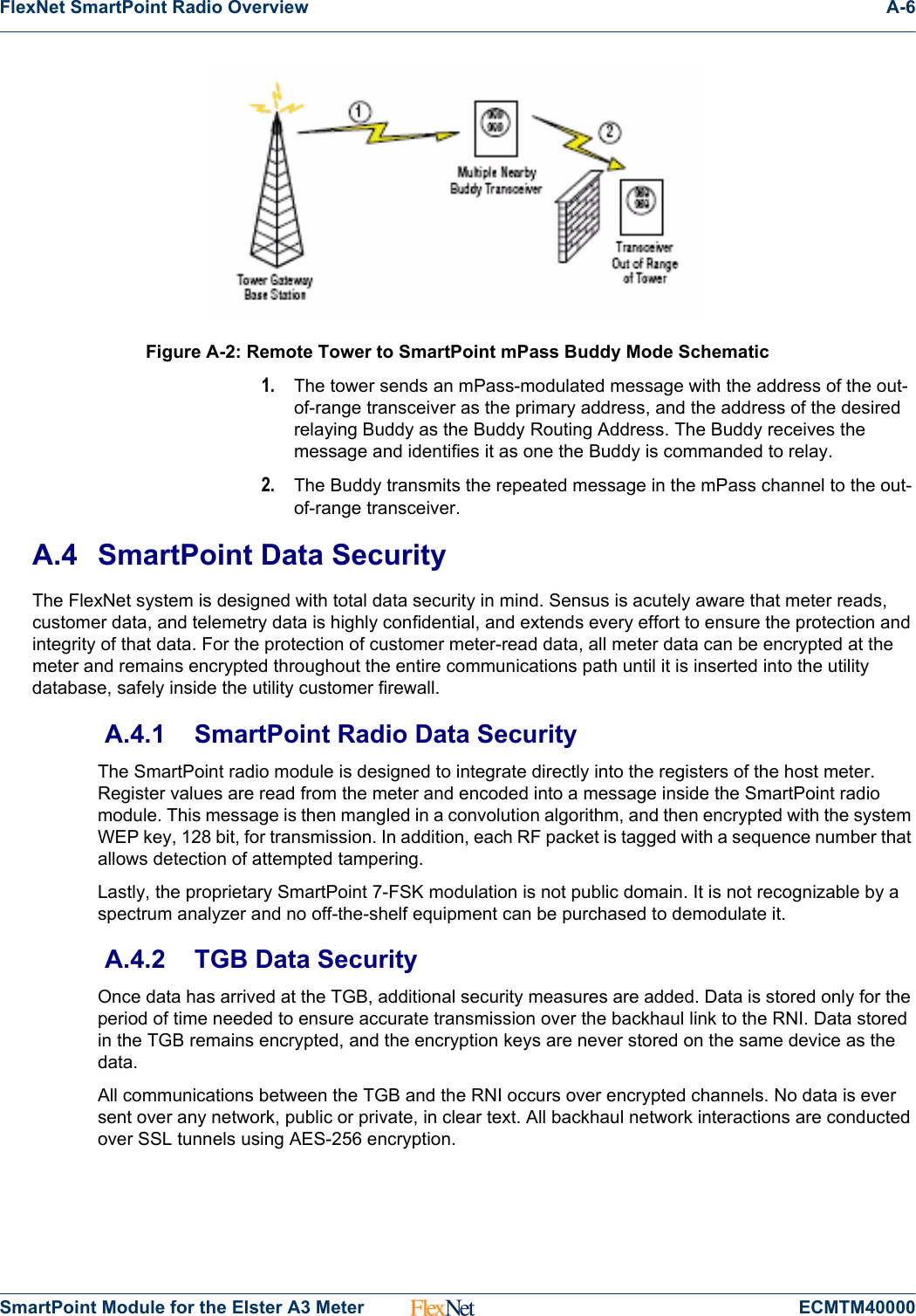
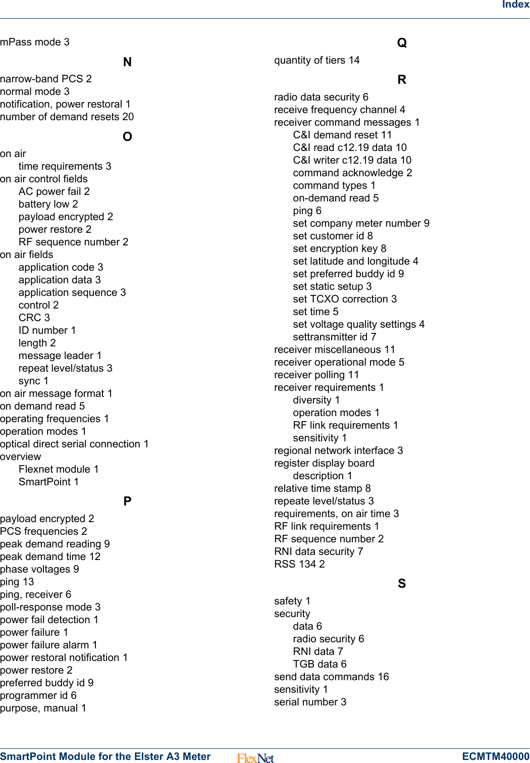
![On Air Message Types 4-30SmartPoint Module for the Elster A3 Meter ECMTM400004.18 C&I High Res Read with History Data—App Code 554.18.1 Application DataThis message contains the C&I High Res Read with History Data as defined in the table below, sent in response to a Meter Read Ping message when the meter is in high res mode.4.18.2 Relative Time StampBytes 0-1. Elapsed time since last meter reading (2 second resolution). This field is used to determine exactly when the meter reading occurred.4.18.3 Delta Data TypeByte 2, bits 0-2. Used to define the amount of time represented in each History Data sample. The valid values for Delta Data Type are defined in the table below:Ping Response to Data Byte (Bits) Field0-1 Relative Time Stamp2Delta Data Type (0:2)Click Count (3:7)3-6 Current Consumption (ST23 SUMMA-TIONS[0])7-10 Peak Demand Reading (ST23DEMANDS[0].DEMAND)11 Phase A Volts ST28 RMSVOLTSA12 Phase B Volts ST28 RMSVOLTSB13 Phase C Volts ST28 RMSVOLTSC14-27 History Data In 1 Wh Resolution, stored in vari-able bin width formatDelta Data Type History Samp Interval (min)051152603360(6 Hours)4720(12 Hours)](https://usermanual.wiki/Sensus-Metering-Systems/FLEXELS/User-Guide-1621763-Page-46.png)