Sensus Metering Systems FLEXELS Radio Telemetry Module User Manual FlexNet Module for the Elster A3
Sensus Metering Systems Inc. Radio Telemetry Module FlexNet Module for the Elster A3
Manual


Revisions
This document contains proprietary information. It is to be used only for the purpose for which it is intended.
Information in this document is subject to change without notice and does not represent a commitment on the part of Sensus Metering Systems-
North America, Inc. No part of this publication may be reproduced, transmitted, stored in a retrieval system, or translated into any language in
any form by any means, without the written permission of Sensus Metering Systems Inc.
© Copyright 2008, Sensus Metering Systems Inc. All Rights Reserved.
FlexNet® and associated logos are trademarks of Sensus Metering Systems Inc. and its subsidiaries and affiliates. All other brand names may
be trademarks of their respective owners.
Sensus Metering Systems
1501 Ardmore Boulevard, Suite 601
Pittsburgh, PA 15221 USA
1-800-METER-IT (638-3748)
1-800-888-2403 (fax)
www.sensus.com
Document:
SmartPoint Module for the Elster A3 Meter
Document Number:
ECMTM40000
Rev No. Date Description
Rev 1 6/26/2008 Updated for hardware and firmware updates to SmartPoint Module.

Table of Contents i
SmartPoint Module for the Elster A3 Meter ECMTM40000
Table of Contents
1 Introduction ........................................................................................................................ 1-1
1.1 Purpose ..................................................................................................................................... 1-1
1.2 Safety ........................................................................................................................................ 1-1
2 SmartPoint Module Overview............................................................................................ 2-1
2.1 FlexNet SmartPoint Assembly .................................................................................................. 2-1
2.2 Labels ....................................................................................................................................... 2-1
2.2.1FCC Label ......................................................................................................................................... 2-1
2.3 FlexNet System Overview ......................................................................................................... 2-1
2.3.1Description of Operation ................................................................................................................... 2-1
2.3.2FlexNet AMI Local RF Network ........................................................................................................ 2-2
2.3.2.1 Meter Endpoints ..................................................................................................................... 2-2
2.3.2.2 Tower Gateway Base Station ................................................................................................. 2-3
2.3.3FlexNet AMI Regional Network Interface ......................................................................................... 2-3
3 On Air Message Format ..................................................................................................... 3-1
3.1 Field Definitions ........................................................................................................................ 3-1
3.1.1Message Leader ............................................................................................................................... 3-1
3.1.2Sync .................................................................................................................................................. 3-1
3.1.3Meter ID Number............................................................................................................................... 3-1
3.1.4Customer ID ...................................................................................................................................... 3-1
3.1.5Control............................................................................................................................................... 3-2
3.1.5.1 RF Sequence Number............................................................................................................ 3-2
3.1.5.2 AC Power Fail......................................................................................................................... 3-2
3.1.5.3 Battery Low............................................................................................................................. 3-2
3.1.5.4 Power Restore........................................................................................................................ 3-2
3.1.5.5 Payload Encrypted ................................................................................................................. 3-2
3.1.6Length .............................................................................................................................................. 3-2
3.1.7Repeat Level / Status ....................................................................................................................... 3-3
3.1.8Application Sequence ....................................................................................................................... 3-3
3.1.9Application Code ............................................................................................................................... 3-3
3.1.10Application Data .............................................................................................................................. 3-3
3.1.11CRC ................................................................................................................................................ 3-3
3.2 On Air Time Requirements ....................................................................................................... 3-3
3.3 Addressing ................................................................................................................................ 3-4
3.3.1Command Addressing....................................................................................................................... 3-4
3.3.2Broadcast Addressing ....................................................................................................................... 3-4
3.3.3Group Addressing ............................................................................................................................. 3-4
3.3.3.1 Group Addressing, Preferred Method..................................................................................... 3-4
3.3.3.2 Group Addressing, Legacy Method (deprecated)................................................................... 3-4
4 On Air Message Types....................................................................................................... 4-1
4.1 On Air Message Types ............................................................................................................. 4-1
4.2 Testing Message – App Code 220 ............................................................................................4-1
4.3 Meter Setup / Configuration Message—App Code 1 ................................................................ 4-2
4.4 Meter Serial Number/Position Binding—App Code 5 ............................................................... 4-3
4.4.1Message Format ............................................................................................................................... 4-3
4.4.2Status Flags ...................................................................................................................................... 4-3

Table of Contents ii
SmartPoint Module for the Elster A3 Meter ECMTM40000
4.4.3Meter Serial Number ......................................................................................................................... 4-3
4.4.4Latitude / Longitude........................................................................................................................... 4-3
4.4.5Programmer ID.................................................................................................................................. 4-4
4.4.5.1 Setup Flags ............................................................................................................................ 4-4
4.5 GPS Mapping Message ............................................................................................................ 4-4
4.5.1Message Format ............................................................................................................................... 4-4
4.5.1.1 Latitude................................................................................................................................... 4-5
4.5.1.2 Speed ..................................................................................................................................... 4-5
4.5.1.3 Heading .................................................................................................................................. 4-5
4.5.1.4 Altitude.................................................................................................................................... 4-5
4.6 Command Message—App Code 7 ........................................................................................... 4-5
4.6.1Message Format ............................................................................................................................... 4-5
4.6.2Command Type................................................................................................................................. 4-5
4.7 Buddy Message—App Code 8 ..................................................................................................4-6
4.7.1Message Format ............................................................................................................................... 4-6
4.7.2Buddy Id ............................................................................................................................................ 4-6
4.7.3Buddy Fields ..................................................................................................................................... 4-7
4.7.4Queue Time ...................................................................................................................................... 4-7
4.7.5Meter Reading Fields ........................................................................................................................ 4-7
4.8 C&I Meter Read With History—App Code 13 .......................................................................... 4-8
4.8.1Message Format ............................................................................................................................... 4-8
4.8.2Relative Time Stamp......................................................................................................................... 4-8
4.8.3Delta Data Type ................................................................................................................................ 4-8
4.8.4Compression Enabled....................................................................................................................... 4-8
4.8.5Current Meter Reading...................................................................................................................... 4-8
4.8.6Peak Demand Reading ..................................................................................................................... 4-9
4.8.7Phase A, B and C Meter Voltages ................................................................................................... 4-9
4.8.8Compression Enabled History Samples............................................................................................ 4-9
4.8.9Fixed Bin Width History Samples.................................................................................................... 4-10
4.9 C&I Tier Data—App Code 14 .................................................................................................4-10
4.9.1Message Format ............................................................................................................................. 4-10
4.9.2Tier Information ............................................................................................................................... 4-11
4.9.2.1 Tier ....................................................................................................................................... 4-11
4.9.2.2 Sub Tier ................................................................................................................................ 4-11
4.9.3Meter Type ...................................................................................................................................... 4-12
4.9.4Selected Data Table........................................................................................................................ 4-12
4.9.5Data Flags / Peak Demand Time .................................................................................................... 4-12
4.9.6Summation Reading (103 resolution).............................................................................................. 4-13
4.9.7Demand Reading (100 resolution) .................................................................................................. 4-13
4.9.8Cumulative Demand Reading (103 resolution) ............................................................................... 4-13
4.9.9Coincident Reading (103 resolution)............................................................................................... 4-13
4.9.10# Demand Resets ......................................................................................................................... 4-13
4.9.11Source Indices .............................................................................................................................. 4-13
4.9.12Quantity of Tier Information........................................................................................................... 4-14
4.9.12.1 Number of Tiers.................................................................................................................. 4-14
4.9.12.2 Number of Sub Tier ............................................................................................................ 4-14
4.9.13Service Quality Message Format .................................................................................................. 4-14
4.10 C&I Tunneling Read—App Code 15 .................................................................................... 4-15
4.11 C&I Alarm Message – App Code 16 ..................................................................................... 4-16
4.11.1Application Data ............................................................................................................................ 4-16
4.11.2Voltage Phase A,B, and C ............................................................................................................ 4-16
4.11.3Click Count.................................................................................................................................... 4-16
4.11.4Time Since Event .......................................................................................................................... 4-16

Table of Contents iii
SmartPoint Module for the Elster A3 Meter ECMTM40000
4.11.5Current Meter Reading.................................................................................................................. 4-17
4.11.6Extended Time Since Event.......................................................................................................... 4-17
4.11.7Device Temperature...................................................................................................................... 4-17
4.11.8µP Status ...................................................................................................................................... 4-17
4.11.9Lock Errors.................................................................................................................................... 4-17
4.11.10Alarm Data .................................................................................................................................. 4-18
4.11.11Time of Last Power Failure ......................................................................................................... 4-18
4.11.12Total # of Outages....................................................................................................................... 4-18
4.11.13Flags ........................................................................................................................................... 4-19
4.12 Demand History Message—App Code 25 ............................................................................ 4-19
4.12.1Message Format ........................................................................................................................... 4-19
4.12.2Number of Demand Resets........................................................................................................... 4-20
4.12.3Last Demand Reset Date and Time.............................................................................................. 4-20
4.12.4Last Peak Demand Date and Time ............................................................................................... 4-20
4.12.5Last Peak Demand........................................................................................................................ 4-20
4.12.6Last Consumption Reading........................................................................................................... 4-20
4.12.72nd Demand Reset Date and Time............................................................................................... 4-20
4.12.82nd Peak Demand Date and Time................................................................................................ 4-20
4.12.92nd Peak Demand ........................................................................................................................ 4-20
4.12.102nd Consumption Reading.......................................................................................................... 4-20
4.13 Load Profile Metadata Message—App Code 28 ................................................................... 4-21
4.14 Load Profile Block Data Message—App Code 29 ................................................................ 4-21
4.15 Firmware Image Check Response—App Code 30 ............................................................... 4-23
4.16 High Res C&I Meter Read with History—App Code 38 ........................................................ 4-23
4.17 Generic Ping Response—App Code 48 ............................................................................... 4-23
4.17.1Demand Enable Status/Interval Configuration .............................................................................. 4-24
4.17.2TOU Enable Status/Tier and Season Configuration ..................................................................... 4-24
4.17.3TOU Current Year Holidays .......................................................................................................... 4-26
4.17.4TOU Next Year Holidays............................................................................................................... 4-26
4.17.5Click History .................................................................................................................................. 4-28
4.17.6Load Limit Status/Threshold ......................................................................................................... 4-28
4.17.7Advanced Voltage Quality Settings............................................................................................... 4-28
4.17.8TOU Auto-Push Options ............................................................................................................... 4-29
4.18 C&I High Res Read with History Data—App Code 55 .......................................................... 4-30
4.18.1Application Data ............................................................................................................................ 4-30
4.18.2Relative Time Stamp..................................................................................................................... 4-30
4.18.3Delta Data Type ............................................................................................................................ 4-30
4.18.4Click Count.................................................................................................................................... 4-31
4.18.5Current Consumption (wH resolution)........................................................................................... 4-31
4.18.6Peak Demand Reading ................................................................................................................. 4-31
4.18.7RMS Volts Phase A-C................................................................................................................... 4-31
4.18.8History Data .................................................................................................................................. 4-31
4.19 Scratch Pad Image Check Response—App Code 57 .......................................................... 4-31
5 Setup and Configuration ................................................................................................... 5-1
5.1 Electrical Configuration Interface .............................................................................................. 5-1
5.1.1Magnetic Loop................................................................................................................................... 5-1
5.1.2Optical Direct Serial Connection (optional) ...................................................................................... 5-1
5.2 Configurable Parameters .......................................................................................................... 5-1
5.2.1End Point ID ...................................................................................................................................... 5-1
5.2.2Meter Sample Rate ........................................................................................................................... 5-2
5.2.3Supervisory Transmit Rate................................................................................................................ 5-2
5.2.4Base Frequency Channel.................................................................................................................. 5-3

Table of Contents iv
SmartPoint Module for the Elster A3 Meter ECMTM40000
5.2.5Transmit Frequency Channels .......................................................................................................... 5-3
5.2.6Receive Frequency Channel............................................................................................................. 5-4
5.2.7C&I Mode Channel............................................................................................................................ 5-4
5.2.8Priority Mode Channel....................................................................................................................... 5-4
5.2.9Transmit Channel Mask .................................................................................................................... 5-4
5.2.10Transmit Operational Mode............................................................................................................. 5-5
5.2.11Receiver Operational Mode ............................................................................................................ 5-5
5.2.12Enable Encryption ........................................................................................................................... 5-6
5.2.13Programmer ID................................................................................................................................ 5-6
5.3 Setup Messages ....................................................................................................................... 5-6
5.3.1Setup Messages ............................................................................................................................... 5-6
5.3.2Basic Command Message Format.................................................................................................... 5-7
5.3.3Basic Reply Message Format ........................................................................................................... 5-9
5.3.4Command / Reply Message Definitions ............................................................................................ 5-9
5.4 Send Data Commands ............................................................................................................ 5-16
6 Receiver Section ................................................................................................................ 6-1
6.1 Receiver Requirements ............................................................................................................ 6-1
6.1.1Operation Modes............................................................................................................................... 6-1
6.1.2RF Link Requirements ...................................................................................................................... 6-1
6.1.3Sensitivity .......................................................................................................................................... 6-1
6.1.4Diversity ............................................................................................................................................ 6-1
6.2 Receiver On Air Command Messages ...................................................................................... 6-1
6.2.1Command Types............................................................................................................................... 6-1
6.2.2Command Acknowledge ................................................................................................................... 6-2
6.2.3Set Static Setup ................................................................................................................................ 6-3
6.2.4Set TCXO Correction ........................................................................................................................ 6-3
6.2.5Set Latitude and Longitude ............................................................................................................... 6-4
6.2.6Set VoltVoltage Quality settings:....................................................................................................... 6-4
6.2.7Set..................................................................................................................................................... 6-5
6.2.8On Demand Read / Drive By Read ................................................................................................... 6-5
6.2.9Ping ................................................................................................................................................... 6-6
6.2.10Set Transmitter Id............................................................................................................................ 6-7
6.2.11Set Customer Id .............................................................................................................................. 6-8
6.2.12Set Encryption Key.......................................................................................................................... 6-8
6.2.13Set Preferred Buddy Id.................................................................................................................... 6-9
6.2.14Set Company Meter Number .......................................................................................................... 6-9
6.2.15C&I Read C12.19 Data ................................................................................................................. 6-10
6.2.16C&I Write C12.19 Data.................................................................................................................. 6-10
6.2.17C&I Demand Reset ....................................................................................................................... 6-11
6.3 Command Addressing ............................................................................................................ 6-11
6.4 Receiver Miscellaneous .......................................................................................................... 6-11
6.4.1Miscellaneous ................................................................................................................................. 6-11
6.4.2Polling ............................................................................................................................................. 6-11
A FlexNet SmartPoint Radio Overview ............................................................................... A-1
A.1 SmartPoint Power Failure Detection and Alarm ......................................................................A-1
Power Fail Detection 1
Power Restoration Notification 1
Brown-Out Detection 1
A.2 Operating Frequencies of SmartPoint/TGB Devices ...............................................................A-1
Systems Operating Under Part 24 of FCC Rules

Table of Contents v
SmartPoint Module for the Elster A3 Meter ECMTM40000
(Narrow-Band PCS) 2
Systems Operating Under RSS-134 in Canada
(Narrow-Band PCS) 2
A.3 SmartPoint Radio Transmit Modes ..........................................................................................A-2
Normal Mode 3
A.3.1.1 Staggered Transmissions .....................................................................................................A-3
A.3.1.2 Poll-response Message Traffic ..............................................................................................A-3
Poll/Response Mode 3
mPass or “Buddy” Transmit Mode 3
A.3.3.1 Buddy Mode Using mPass Transmissions ............................................................................A-5
A.3.3.2 Tower mPass Buddy Mode to ORD Command Transmissions ............................................A-5
A.4 SmartPoint Data Security ........................................................................................................A-6
SmartPoint Radio Data Security 6
TGB Data Security 6
RNI Data Security 7
Separation of Customer Data 7
B Specifications ................................................................................................................... B-1
B.1 External AC Line Power ...........................................................................................................B-1
B.2 Current Consumption ...............................................................................................................B-1
B.3 Power Failure ...........................................................................................................................B-1
B.4 Internal Power Supplies ............................................................................................................B-2
B.4.1 Micro Power Regulator ....................................................................................................................B-2
B.4.2 DC to DC Converter.........................................................................................................................B-2
B.5 Start Up Timing Requirements .................................................................................................B-2
Introduction 1-1
SmartPoint Module for the Elster A3 Meter ECMTM40000
1 Introduction
1.1Purpose
This manual provides technical information for the FlexNet SmartPoint module installed in the Elster A3 meter.
This document is intended for technically qualified personnel of energy supply companies and their contractors
who are responsible for the system planning, installation, commissioning, operation, maintenance,
decommissioning, and/or disposal of meters.
1.2Safety
You must observe all industry safety precautions during all phases of operation, service, and servicing of the
meters. Failure to comply with these precautions or with specific warnings in this manual violates safety standards
of design, manufacture, and the intended use of the metering instrument. Sensus Metering Systems assumes no
liability for the customer’s failure to comply with these requirements.
WARNING
Hazardous voltages are present while power is applied to meters, meter sockets, or other
metering equipment. Any work on the energized equipment presents the danger of
electrical shock and can result in death or serious injury. The information contained within
this manual is intended to be an aid to qualified metering personnel. It is not intended to
replace the extensive training necessary to handle metering equipment in a safe manner.
Use extreme care when servicing the meter while power is applied.
CAUTION
All work on this product should be performed by qualified electricians and metering
specialists in accordance with local utility safety practices, utility requirements, and
procedures outlined in Chapter 14 of The Handbook for Electricity Metering, 10th Edition.
Failure to comply with this caution can result in the destruction of or damage to the
equipment.
!

SmartPoint Module Overview 2-1
SmartPoint Module for the Elster A3 Meter ECMTM40000
2 SmartPoint Module Overview
2.1 FlexNet SmartPoint Assembly
The SmartPoint assembly consists of a SmartPoint printed circuit board and a separate antenna printed circuit
board. A 20-pin connector joins the SmartPoint module to the sensor board.
The SmartPoint module is installed on three plastic standoffs inserted in the sensor board. The antenna is
fitted into a slot on the side of the base. A 20-pin connector joins the SmartPoint module to the sensor board.
The FlexNet SmartPoint module contains a micro-controller, a FlexNet transceiver, and a FlexNet AMI
antenna. See Section 2.3 for more information on the FlexNet System, and see Appendix A for a more detailed
FlexNet SmartPoint overview.
The transceiver operates between 800 and 960 MHz, with each 100 MHz operation band (800, 900 MHz)
requiring a slightly different build, using alternate capacitors, inductors, possibility layouts, and antennas.
The authorized SmartPoint bandwidth is 25 kHz.
• The transceiver is capable of multiple on-air modulation formats, including:
• Normal mode, for standard transmissions,
• Message Pass mode for messages optionally repeated by a receiver-capable meter, and
• Poll/Response mode, for providing a clear channel for responses from tower commands.
2.2 Labels
2.2.1 FCC Label
The FCC label may:
• contain patent and part numbers,
• provide relevant FCC Part 15 compliance information for the integrated AMI card,
• describe the operating conditions, or
• contain a warning for disposal in the event that the AMI card contains Mercury.
If installing a new AMI card, this label is attached to the register cover.
2.3 FlexNet System Overview
The FlexNet System enhances the Elster meter by providing Advanced Metering Reading (AMR) capability.
See Appendix A for a more detailed overview of the FlexNet SmartPoint.
2.3.1 Description of Operation
The FlexNet data collection and command network is comprised of two parts:
• Local RF Network, and
• Regional Network Interface (RNI).
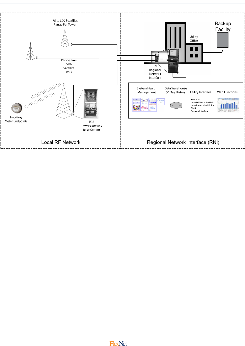
: FlexNet Fixed Base AMI Network Overview2-1, FlexNet AMI Network Overview, exhibits the general
structure of the communications network employed to access and retrieve meter data.
SmartPoint Module Overview 2-2
SmartPoint Module for the Elster A3 Meter ECMTM40000
Figure 2-1: FlexNet Fixed Base AMI Network Overview
2.3.2 FlexNet AMI Local RF Network
The Local RF network consists of FlexNet SmartPoint modules (transceivers) located at each meter,
and a network of FlexNet Tower Gateway Base Stations (TGBs).
2.3.2.1 Meter Endpoints
The integrated SmartPoint module communicates with the Elster A3 bus to provide internal AMR
capability to the Elster meter for use on commercial services. The module:
•directly reads the data in the meter (energy),
•provides control capabilities to reset the meter Demand and operate control
relays, and
•monitors service voltage to provide real-time outage and restoration alarms.

SmartPoint Module Overview 2-3
SmartPoint Module for the Elster A3 Meter ECMTM40000
Figure 2-2: Elster Meter with SmartPoint Module Installed
The SmartPoint modules transmit the meter consumption and status information at regular
intervals. Critical meter status and power outage alarms are also monitored on a real-time basis.
The SmartPoint module transmits the meter data to the fixed network using long-range, licensed,
narrowband radio.
The SmartPoint is also able to use mPass Mode, which allows a SmartPoint module to repeat a
data transmission from another SmartPoint device that is blocked from the TGB transceiver, and
allows the TGB transceiver to communicate with a blocked SmartPoint module through another
SmartPoint module.
2.3.2.2 Tower Gateway Base Station
These transmissions are received by one or more TGBs. The TGBs use existing radio towers;
antennas are installed at heights of 200’-650’, providing coverage of 75 to 300 sq. mi. The TGB
includes a Linux computer that communicates to the RNI (see below) via modem. The TGB
forwards the data to the Regional Network Interface (RNI) via phone line, ISDN, Satellite, or WiFi
links, and stores the information locally in the event of RNI communications path interruption. The
transceiver allows for two-way communication over the FlexNet AMI network, allowing commands
to be issued to the SmartPoint modules.
2.3.3 FlexNet AMI Regional Network Interface
The RNI consists of modems and Linux computers with backup power. The RNI controls the TGB sites
and keeps a 60-day log of metering data. It also includes an SQL database that generates reports for
billing and other external system elements. Interfaces are available to a variety of metering databases:
Sensus SiMS, Itron MV-90 and Enterprise Edition. XML and customized interfaces are available.

SmartPoint Module Overview 2-4
SmartPoint Module for the Elster A3 Meter ECMTM40000
2.4 SmartPoint Terminology
On-Air Messages (see Chapters 3 and 4). This term is used to describe messages sent by FlexNet endpoint
devices. The exception to this is the command message, which carries On Air Commands from the RNI
through the TGB to the endpoint (see Section 4.6).
Serial Commands (see Chapter 5). These messages are used to control a FlexNet endpoint device over a
serial interface. Many devices have a receive-only inductive coupled interface (called the Mag Loop), while
others feature a RS-232 serial interface. This creates a situation where devices receive commands over the
serial interface but respond over RF. For example, devices will respond to Ping Commands received on the
serial interface by sending a response out of the Flexnet RF interface. Devices that have RS232 interfaces
support 2-way serial communications in certain cases, such as when supporting firmware upgrade over the
srerial port.
On Air Commands (see Chapter 6): The various types of command messages are used for configuring and
querying the endpoint devices.
Ping Commands (see Section 6.2.9): This is a specific On Air Command (Type 8) that is used to query status
and readings from the endpoint devices.
For example, to get a meter to send a Setup/Configuration Message (defined in Section 4.3), you send it an On
Air Command (7) message with a command-type of Ping (8) and a Ping type Setup (15); the meter will respond
with the Setup/Command On Air Message.

On Air Message Format 3-1
SmartPoint Module for the Elster A3 Meter ECMTM40000
3 On Air Message Format
All fields are sent least-significant byte first.
The basic format of the on air message is as shown in the following table:
3.1 Field Definitions
3.1.1 Message Leader
This is a repeating stream of the value 0xAA used by the receiver to trip and synchronize to the
transmitted message. The leader is 152 bits or 19 bytes long.
3.1.2 Sync
8 bit Start of Message signal (0x36).
3.1.3 Meter ID Number
A unique identifier, different and fixed for each end point device, 28 bits long.
3.1.4 Customer ID
4 Bits of Customer ID.
Bytes
(Bits)
Field Description Value
0-18 Leader 0xAA
19 Sync Start of Msg 0x36
20-
23(0:3)
Meter ID
23(4:7) Customer ID 0x0
24 Control Control: 4 bits; Flags: 4 bits
25 Length 0x03 – 0xFF
26 Repeat Level/Sta-
tus
Repeat Level: 2 bits; Status: 6 bits
27 App Sequence
28 App Code
29-56 App Data 0-252 bytes, currently fixed at 28
bytes
57-60 CRC

On Air Message Format 3-2
SmartPoint Module for the Elster A3 Meter ECMTM40000
3.1.5 Control
Provides status data to the receiver.
3.1.5.1 RF Sequence Number
A 4 bit modulo 16 counter, increments each RF transmission.
3.1.5.2 AC Power Fail
Set if AC Power is not present. In AC only powered end point devices, set in Last Gasp messages.
3.1.5.3 Battery Low
Tested under load, this bit is set if the input voltage is below a certain threshold. The bit is valid on
next transmitted message.
3.1.5.4 Power Restore
Set in the first new message after a power up, cleared otherwise.
3.1.5.5 Payload Encrypted
Set if the payload data has on-air encryption turned on, cleared otherwise.
3.1.6 Length
The number of remaining data bytes in the on air message not including the CRC bytes. Initially, there
will be 1 fixed value of length to facilitate receiver firmware functionality: 31 bytes.
Bits Control
0-3 RF Sequence Number
4 AC Power Failed
5 Power Restored
6 Low Battery Detected
7 Payload Encrypted

On Air Message Format 3-3
SmartPoint Module for the Elster A3 Meter ECMTM40000
3.1.7 Repeat Level / Status
3.1.8 Application Sequence
An 8 bit modulo 256 counter that increments every time new application data is transmitted by the end
point device.
3.1.9 Application Code
An 8 bit code used to determine the format of the data in the Application Data field.
3.1.10 Application Data
Between 0 and 252 bytes of application data in the future, fixed at 28 for now.
3.1.11 CRC
The 32 bit CCITT Cyclical Redundancy Check sum of all of the bytes from the ID field to the last
Application Data field. Allows for bit error detection and single bit error correction.
3.2 On Air Time Requirements
On air messages take differing amounts of airtime depending on modulation format. The message length of
every message is fixed at 31 bytes. The table below shows the transmission time for each combination:
Bits Repeat Level / Status
0 History Overflow
1In Time Sync
2Tamper
3Brown Out
4 Meter Read Failure
5 RF Sequence Number MSB
6-7 Repeat Level
Modulation Error Correction Rate
(Hz)
Msg Time
(msec)
Normal Baud Interleaved, Convolutionally
Encoded
8044.5544 107.40
mPass Baud Interleaved, Convolutionally
Encoded
5000.0000 157.60
Boost Baud Interleaved, Convolutionally
Encoded
804.4554 1074.02
Half Baud Interleaved, Convolutionally
Encoded
4022.2772 214.80

On Air Message Format 3-4
SmartPoint Module for the Elster A3 Meter ECMTM40000
3.3 Addressing
Endpoint addresses are also called Meter ID, FlexNet ID, or Tx ID. In a FlexNet protocol packet, the endpoint
address is carried in the Meter ID field defined above.
3.3.1 Command Addressing
The Receiver will accept commands that are addressed to it via the Device ID of the on air message.
The three accepted addresses are one that matches its own Device ID, one using the Broadcast
Address, or, lastly, one using the Group Address.
3.3.2 Broadcast Addressing
A message sent with the Broadcast Address, which is all 1’s or 0xFFFFFFF = 268435455, is
processed by all meters if the message is a command type that can be broadcast. Broadcast
messages are not acknowledged.
3.3.3 Group Addressing
FlexNet group addressing can follow one of two conventions.
3.3.3.1 Group Addressing, Preferred Method
The preferred method is to set the Group Address Indicator bit in the Repeat Level/Status byte as
described in Section 3.1.7 and then place the destination group address in the Meter ID Number
field as described in Section 3.1.3. All modern FlexNet endpoints support this method. This does
not work with early FlexNet devices.
3.3.3.2 Group Addressing, Legacy Method (deprecated)
A message sent with the Tx Id Number field set to Group Address, which is all 1’s except for the
last bit or 0xFFFFFFE = 268435454 is a legacy Group Addressed message. For legacy group
addressed messages except for Ping Command types, the group address is found at byte offset
23-26 of the application data. For Ping Command messages, the group address is found at byte
offset 9-12 of the application data, see Section 5.3.4.

On Air Message Types 4-1
SmartPoint Module for the Elster A3 Meter ECMTM40000
4 On Air Message Types
All fields are sent least-significant byte first unless otherwise specified.
The format of the data in the Application Data field dependent on the value of the Application Code field as follows
and is always 28 bytes in length.
4.1 On Air Message Types
4.2 Testing Message – App Code 220
Message Format: This is a test only message and has mostly static Application Data. Application Data byte 1
has a sequence counter field which counts up one every time the 4 bit sequence counter in the control byte
Application Code Message
220 Testing Message
1 Meter Setup and Configuration
5 Serial #/Postition Binding
6 GPS Mapping Message
8 Buddy Information Message
13 C&I Meter Read with History
14 C&I Tier Data
15 C&I C12.19 Tunneling Read
16 C&I Alarm Message
22 Extended Setup Information
25 Demand History Message
28 Load Profil Meta Data
29 Load Profile Block Data
30 Firmware Image Check
38 High Res. C&I Meter Read with History
48 Generic Ping Response
55 C&I High Res Read with Pulse Data
57 Scratch Pad Image Check

On Air Message Types 4-2
SmartPoint Module for the Elster A3 Meter ECMTM40000
rolls over (every 16 messages). The Application Data below show an example of the Testing Message with a
sequence number of 0x64:
0x0064000102030405060708090a0b0c0d0e0f10111213141516171819
4.3 Meter Setup / Configuration Message—App Code 1
Message Format: After an end point is configured to read meter data, it transmits a Meter Setup /
Configuration message containing a report on how it is configured; it has the following Application Data field
format:
Byte (Bits) Field
0 Firmware Version
1 Device Type
2 (0:2) Meter Sample Rate
2 (3:7) Supervisory Transmit Rate
3 Base Frequency
4-5 Transmit Channel A
6-7 Transmit Channel B
8-9 Transmit Channel C
10-11 Transmit Channel D
12-13 Receiver Channel
14-15 Boost Mode Channel
16 (0:3) Boost Mode Sub-Channel
16 (4) Boost Mode Hopping
16 (5:7) Transmit Channel Mask
17 (0:3) Transmitter Operational Mode
17 (4:6) Receiver Operational Mode
17 (7) Enable Encryption
18-19 Real Time Clock
20-21 TXCO Correction
22-24 A/D Calibration
25 Minimum Click Duration
26 (0:5) Minimum Voltage Threshold
27 (0:3) Outage Time Threshold

On Air Message Types 4-3
SmartPoint Module for the Elster A3 Meter ECMTM40000
Specific definitions for these fields are shown in Chapter 5, with the exception of the first two fields, Firmware
Version and Device Type. Firmware version contains the version of the firmware of the device. If the most
significant bit of Firmware version is set, the firmware is a beta test set.
The Device Type is currently defined as Device Type 5.
4.4 Meter Serial Number/Position Binding—App Code 5
4.4.1 Message Format
This message contains the meter Serial Number and also the installation latitude and longitude (if
position is programmed in at installation time). The message has the following format.
4.4.2 Status Flags
Only bit 0 is currently used and is the Just Programmed Bit. It is set if the device has received a static
setup in the last 5 minutes. The remaining bits are (reserved) and are set to 0.
4.4.3 Meter Serial Number
A 13 byte field containing the ASCII Serial Number reported by the end point device’s associated
meter display board.
4.4.4 Latitude / Longitude
These fields contain a floating point representation in degrees of the end point device’s installation
latitude and longitude. These fields are set using the installer with the installation tool, the end point
has no on board GPS capability.
27 (0:3) Outage Time Threshold
27 (4:7) Restored Time Threshold
App
Data
Byte
01-13 14-17 18-21 22-23 24
Data
Status
Flags
Meter
Serial
Number
Latitude Longitude Programmer
ID
Setup
Flags
Byte (Bits) Field

On Air Message Types 4-4
SmartPoint Module for the Elster A3 Meter ECMTM40000
4.4.5 Programmer ID
The 16 bit ID of the handheld programmer used to setup the device.
4.4.5.1 Setup Flags
An 8 bit field indicating which setup messages have been received by the device. The individual
bits in the byte are defined below:
4.5 GPS Mapping Message
4.5.1 Message Format
This is a special message used for radio coverage mapping and requires an attached GPS module.
Bytes 16 to 27 are reserved.
Bit Setup Message
Received
0Set ID
1 Static Setup
2 Set Crystal Offset
3 Set Lat / Long
4 Set Meter Reading
5 Set Voltage Quality Levels
6 Set Encryption Key
7 (reserved)
App Data
Byte Data
0-2 Reserved
3-5 Latitude (MSB First)
6-8 Longitude (MSB First)
9-10 Speed
11-12 Heading
13-14 Altitude

On Air Message Types 4-5
SmartPoint Module for the Elster A3 Meter ECMTM40000
4.5.1.1 Latitude
These fields contain a representation, in degrees of the end point device’s installation latitude as
presented by the attached GPS module. The actual latitude can be calculated using the following
formula:
Latitude (degrees) = (3 Byte App Data Latitude) * 90.0/8388608
Negative values are in the southern hemisphere; positive values are in the northern hemisphere.
Longitude
These fields contain a representation in degrees of the end point device’s installation longitude as
presented by the attached GPS module. The actual longitude can be calculated using the
following formula:
Longitude(degrees) = (3 Byte App Data Longitude) * 180.0 / 8388608
Negative values are in the western hemisphere, positive values are in the eastern hemisphere.
For example, an App Data Latitude of 0x bff2d7 yields a latitude in degrees of -90.07229, or
90.07229 West.
4.5.1.2 Speed
This field contains the velocity of the endpoint device in 0.01 knot resolution and is sent LSB first.
4.5.1.3 Heading
This field contains the device’s heading in 0.01 degree resolution and is sent LSB first.
4.5.1.4 Altitude
This field contains the device’s altitude in 0.1 meter resolution.
4.6 Command Message—App Code 7
4.6.1 Message Format
This is a Command Message sent by a TGB ( Tower Gateway Basestation ) or a repeating two-way
device. The format of bytes 1-27 are variable based upon command type.
4.6.2 Command Type
This field contains the type of data in the command as shown below, specific formats for each
message can be found in Section 6.2, Receiver On-Air Command Formats.
App Data
Byte 01 - 27
Data Command Type Command Data

On Air Message Types 4-6
SmartPoint Module for the Elster A3 Meter ECMTM40000
4.7 Buddy Message—App Code 8
4.7.1 Message Format
This is a message sent by a relaying two way transmitter sent after repeating a message in order to
build routing information in the central database. Meter reading data from the repeating device has
been added to the previously unused portion of the Buddy Message for extra system redundancy. The
format of the Buddy Message is shown below:
If the Extended Buddy Report bit is set, bytes 10 to 27 are set as follows:
4.7.2 Buddy Id
This field contains the Id of the unit that has been relayed.
App Data
Byte Data
0-3 Buddy ID
4 Buddy App Code
5 Buddy RF Sequence
6 Buddy App Sequence
7 Received Signal Level
8 Received Noise Level
9 (0:6) Queue Time
9 (7) Extended Buddy Report
10-11 Relative Time Stamp
12-14 Current Reading
15-27 History Samples
App Data
Byte Data
10 Embedded App Code (13)
11-12 Relatvie Time Stamp
13-15 Delta Data Type/Current
Reading
16-19 Peak Demand
20-27 History Samples

On Air Message Types 4-7
SmartPoint Module for the Elster A3 Meter ECMTM40000
4.7.3 Buddy Fields
These fields represent the values received in the message from the device that has been buddy
relayed.
4.7.4 Queue Time
The time in seconds that the buddy device stored the message before forwarding it.
4.7.5 Meter Reading Fields
These fields, Relative Time Stamp, Current Reading and History Samples have the same format as
that defined in the Type 12 Meter Read Message.

On Air Message Types 4-8
SmartPoint Module for the Elster A3 Meter ECMTM40000
4.8 C&I Meter Read With History—App Code 13
4.8.1 Message Format
This is the standard meter reading message and has the following format:
4.8.2 Relative Time Stamp
16 bits of byte 0-1, elapsed time since last meter reading. Time is always represented in two-second
resolution.
4.8.3 Delta Data Type
3 bits, bits 0-2 of byte 2. Used to define the amount of time represented by each History Sample in
bytes 8-27. The valid values for Delta Data Type are defined in the table below.
4.8.4 Compression Enabled
1 bit, bit 3 of byte 2. If set, the History Sample in bytes 8-27 are sent in the data compression enabled
format. If cleared, the History sample bytes are sent in the fixed bin width format.
4.8.5 Current Meter Reading
20 bits, bits 4-7 of byte 2 and all of bytes 3 and 4. The total power consumption represented in binary
in kWh.
App Data
Byte 0-1 2-4 5-8 9-11 12-27
Data
Relative
Time
Stamp
Delta Data
Type / Current
Reading
Peak
Demand
Reading
Phase A,
Phase B,
Phase C
Voltage
History Samples
Delta
Data
Type
History
Samp
Interval (min)
Max Pulses
per Interval
Likely
Transmit
Rate
05 28.33 30 min
115 85.00 1 Hr
260 340.00 4 Hr
3360
(6 Hours) 2040.00 6 Hr
4720
(12 Hours) 4080.00 12 Hr
51440
(24 Hours) 8160.00 12 Hr

On Air Message Types 4-9
SmartPoint Module for the Elster A3 Meter ECMTM40000
4.8.6 Peak Demand Reading
32 bits, all of bytes 5-8. The peak demand reading is represented as a four byte floating point number
in W.
4.8.7 Phase A, B and C Meter Voltages
Three 8 bit fields containing meter line voltage readings of the voltage for all available phases at the
time of the meter reading. The values in the fields can be converted to voltage using the following
formula which provides voltages from 50 to 560 volts:
Voltage = Value*2 + 50
4.8.8 Compression Enabled History Samples
All bits of bytes 12-27 compressed using a Huffman Binary Tree compression algorithm. As many
History Sample bins as possible are packed into the remaining space in the on air message, up to 136
bins in the minimum case. Each history sample is stored as the difference from the last reading.
The Codex used to encode the histories is shown in the following table:
Scanning begins at bit 0 of byte 0 and goes to ms bit of byte 0 before rolling down to the ls bit of byte 1
on through the history buffer..
To decode, scan through the buffer counting consecutive 1’s. When a 0 is reached, that denotes the
end of the Key Bit Pattern. The number of consecutive ones indicates the specific symbol.
If the end of the buffer is reached before a complete valid symbol is reached, ignore that history value.
Key Bit Pattern
(binary)
History
Value
Required
Number of
Bits
Comment
001
10 1 2
110 2 3
1110 3 4
11110 4 5
111110 5 6
1111110xxxxx 6-37 11 If 0x7E is detected, the
next 5 bits + 6 = value
11111110xxxxxxxxxxxxx
38-8213 21
If 0xFE is detected, the
next 13 bits + 38 =
value
11111111 N/A N/A End of usable history,
end history processing

On Air Message Types 4-10
SmartPoint Module for the Elster A3 Meter ECMTM40000
4.8.9 Fixed Bin Width History Samples
All bits of bytes 12-27. As many History Sample bins as possible are packed into the remaining space
in the on air message. Each history sample is stored as the difference from the last reading. Note: A
residential meter at maximum load can generate 346 counts per hour. The size and number of History
Sample bins in the message are determined by the Delta Data Type field are shown in the following
table (6-7 are reserved).
4.9 C&I Tier Data—App Code 14
4.9.1 Message Format
This message is used to transmit tier data from the C12.19 Standard Table 23 and has the following
format (Note that Tier 7 is a special case to report Service Quality and has a different format).
Delta
Data
Type
History
Sample
Interval
(min)
Max
Pulses
per
Interval
Required
# Bits
#
Available
Bins
Total
History
(Hours)
Likely
Transmit
Rate
05 28.33 5 25 2.333 30 min
115 85.00 7 18 5 1 Hr
260 340.00 9 14 16 4 Hr
3360
(6 Hours) 2040.00 11 11
78
(3.25
days)
6 Hr
4720
(12 Hours) 4080.00 12 10 144
(6 days) 12 Hr
51440
(24 Hours) 8160.00 13 9 264
(11 days) 12 Hr
App Data Bytes Data
0 Tier Information
1 (0:5) Meter Type
1 (6:7) Selected Data Table
2-4 Data Flags / Peak Demand Time
5-8 Summation Reading (103 resolution)
9-12 Demand Reading (100 resolution)
13-16 Cumulative Demand Reading
(102 resolution)
17-20 Coincident Reading (103 resolution)

On Air Message Types 4-11
SmartPoint Module for the Elster A3 Meter ECMTM40000
4.9.2 Tier Information
8 bits of byte 0 (bit 7 is reserved). Used to identify the tier and sub tier of the data in this message. A
separate message is sent for each Tier and SubTier configured in the meter as defined in the
following tables:
4.9.2.1 Tier
Bits 0-2 of the Tier Information byte is defined in the following table:
4.9.2.2 Sub Tier
Bits 3-6 of the Tier Information byte is used when individual Tiers have more than one Summation,
Demand or Coincident reading in a single Tier
21 # Demand Resets
22 Summation Source Index
23 Demand Source Index
24 Coincident Source Index
25 Quantity of Tier Information
Bits Description
0-2 Tier
3-6 Sub Tier
7 (reserved)
Value Tier
0 Totalization
1Tier A
2Tier B
3Tier C
4Tier D
5-6 (reserved)
7 Service Quality
App Data Bytes Data

On Air Message Types 4-12
SmartPoint Module for the Elster A3 Meter ECMTM40000
4.9.3 Meter Type
Lower 6 bits of byte 1. The type of data and unit of measure reported in the tier data message is
dependant on the meter type as defined below:
4.9.4 Selected Data Table
Upper 2 bits of byte 1. This selects data from table ST-23, ST-24, or ST-25:
4.9.5 Data Flags / Peak Demand Time
Bytes 2-4. Data flags which data fields are available in this message. Peak Demand Time contains the
time and date of the Peak Demand.
Value Meter Type
0 (reserved)
1Elster A3R
2Elster A3K
3Elster A3D
4Elster A3T
5Elster A3Q
6-255 Reserved
Value Table
0 ST-23 Standard Data Table
1 ST-24 Previous Season Data Table
2 ST-25 Demand Reset Data Table
3 Reserved
Byte (Bits) Description
2 (0)
Cumulative Demand Type:
0 – Cumulative
1 – Continuously Cumulative
2 (1)
Summation Available This Message
0 – No
1- Yes
2 (2)
Demand Available This Message
0 – No
1- Yes
2 (3)
Coincident Available This Message
0 – No
1- Yes

On Air Message Types 4-13
SmartPoint Module for the Elster A3 Meter ECMTM40000
4.9.6 Summation Reading (103 resolution)
Bytes 5-8. The Summation for this Tier and Sub Tier in represented as a floating point number in kilo
resolution.
4.9.7 Demand Reading (100 resolution)
Bytes 9-12. The Demand for this Tier and Sub Tier represented as a floating point number in 100 unit
resolution.
4.9.8 Cumulative Demand Reading (103 resolution)
Bytes 13-16. The Cumulative Demand Reading for this Tier and Sub Tier represented as a floating
point number kilo resolution. Whether this value is Cumulative or Continuously Cumulative is defined
by Bit 0 of Byte 1.
4.9.9 Coincident Reading (103 resolution)
Bytes 17-20. The Coincident Reading for this Tier and Sub Tier represented as a floating point number
in kilo resolution.
4.9.10 # Demand Resets
All bits of Byte 21. The number of Demand Resets detected by the meter.
4.9.11 Source Indices
The definitions for the ANSI C12.19 Source Index fields (bytes 22 to 25) are based upon the Meter
Type in byte 1. The Source Index definitions are meter-manufacturer specific. Refer to the Elster A3
technical manual for the meter’s ANSI C12.19 details.
2 (4-7) Peak Demand Month
0-11 = Jan-Dec
3 (0-4) Peak Demand Day
1-31 = 1st to the 31st
3 (5-7), 4 (0-1) Peak Demand Hour
0-23 = Midnight to 11:00pm
4 (2-7) Peak Demand Minute
0-59

On Air Message Types 4-14
SmartPoint Module for the Elster A3 Meter ECMTM40000
4.9.12 Quantity of Tier Information
8 bits of byte 23 (bit 7 is reserved). Used to report the total number of tiers and sub tiers in all of the tier
data in this messages as defined in the following tables:
4.9.12.1 Number of Tiers
Bits 0-2 of the Quantity of Tier Information byte which represent the number of reported tiers not
including the Totalization tier. For example, if Tiers A,B,C, and D were configured in a meter, then
Number of Tiers would be set to 4. 5 sets of tier information would actually be sent, 1 for the
Totalization, and 1 for each of the 4 tiers.
4.9.12.2 Number of Sub Tier
Bits 3-6 of the Quantity of Tier Information byte which represent the number of Sub Tiers sent for
each tier. The minimum is 1, the maximum is 10.
4.9.13 Service Quality Message Format
This message is used to transmit Service Quality and is identified by being special Tier number 7.
Bits Description
0-2 Number of Tiers
3-6 Number of Sub Tiers
7 Reserved
App Data
Bytes Data
0 Tier Information ( Tier = 7, SubTier Field reserved )
1-2 Service Frequency ( 0.1 Hz resolution )
3-4 RMS Amps Phase A (0.1 Amp resolution)
5-6 RMS Amps Phase B (0.1 Amp resolution)
7-8 RMS Amps Phase C (0.1 Amp resolution)
9-10 RMS Volts Phase A (0.1 Volt resolution)
11-12 RMS Volts Phase B (0.1 Volt resolution)
13-14 RMS Volts Phase C (0.1 Volt resolution)
15-16 Phase Angle B-A (0.1 degree resolution)
17-18 Phase Angle C-A (0.1 degree resolution)
19-20 Power Factor Angle Phase A (0.1 degree resolution)
21-22 Power Factor Angle Phase B (0.1 degree resolution)
23-24 Power Factor Angle Phase C (0.1 degree resolution)

On Air Message Types 4-15
SmartPoint Module for the Elster A3 Meter ECMTM40000
4.10 C&I Tunneling Read—App Code 15
Message Format: This message is used to transmit raw C12.19 table data in response to a C12.19 Table
Read Command. The Application Sequence number of this message matches that of the Table Read
Command. The C12.19 table and offset of the raw data also match the command. If the number of returned
bytes is 0, then an error has occurred reading the table.
App Data
Bytes Data
0 Number of returned bytes
1-27 Raw Data bytes

On Air Message Types 4-16
SmartPoint Module for the Elster A3 Meter ECMTM40000
4.11 C&I Alarm Message – App Code 16
4.11.1 Application Data
This message contains alarm data from the meter and is also used to report power failures.
4.11.2 Voltage Phase A,B, and C
The current voltage reported by the meter for all three phases:
Voltage Phase n = Value*2
4.11.3 Click Count
An 8 bit field containing the number of times AC voltage loss has been detected by the meter.
4.11.4 Time Since Event
An 8 bit fields containing the time in 6 second resolution since a power failure or power restoration
actually occurred.
App Data
Bytes Data
0 Voltage Phase A
1 Voltage Phase B
2 Voltage Phase C
3 Click Count
4 Time Since Event
5-6 Extended Time Since Event
7-9 Current Reading
10 Device Temperature
11 µP Errors
12 Lock Errors
13-14 Meter Alarm Flags
15 # Manual Demand Resets
16-19 Time of Last Power Fail
20-23 Time of Last Power Restore
24 Total # of Outages
25 Flags

On Air Message Types 4-17
SmartPoint Module for the Elster A3 Meter ECMTM40000
4.11.5 Current Meter Reading
20 bits, of the meter setting. All 6 decimal meter digits represented in binary.
4.11.6 Extended Time Since Event
A 16 bit fields containing the MS two bytes of Time Since Event in 1536 second resolution since a
power failure or power restoration actually occurred. This yields over 3 years of possible
measurement. The overall Time Since Event can be calculated using the following formula:
Total Time Since Event = (Extended Time Since Event)* 1536 + (Time Since Event)*6
4.11.7 Device Temperature
An 8 bit signed value containing the current device temperature in degrees Celsius.
4.11.8 µP Status
Microprocessor Status, 8 bits with 3 fields. RAM and ROM Tests are run once at boot-up. Processor
Rests is a one up counter that increments once every time the microprocessor is reset. This field is
cleared by a static setup message. The bit fields are defined in the table below:
4.11.9 Lock Errors
Voltage Controlled Oscillator Errors, 8 bits with 2 fields. Rx Calibration Errors is a one up counter that
increments once every time the receiver chip is commanded to calibrate and fails. Synthesizer Lock
Failures is a one-up counter that increments once every time the transmitter is commanded to lock to
a frequency and fails. These fields are cleared by a static setup message. The bit fields are defined in
the table below:
Bits Description
7:6 Reserved
5 RAM Test Failed
4 ROM Test Failed
3:0 Processor Resets
Bits Description
7:4 Receiver Calibration Errors
3:0 Synthesizer Lock Failures

On Air Message Types 4-18
SmartPoint Module for the Elster A3 Meter ECMTM40000
4.11.10 Alarm Data
All bits, bytes 13-14. The Alarm provides 16 bit fields, each of which can represent a different failure
mode as shown in the table below.
4.11.11 Time of Last Power Failure
The time and date of the last power failure, as defined in the table below:
4.11.12 Total # of Outages
The total number of outages since meter was configured.
Byte,
Bit Description
13, 0 Meter Unprogrammed
13, 1 Configuration Error
13, 2 Self check Error
13, 3 RAM Failure Error
13, 4 ROM Failure Error
13, 5 NONVOL Error
13, 6 Clock Error
13, 7 Measurement Error
14, 0 Low Battery Error
14, 1 Low Loss Potential
14, 2 Demand Overload
14, 3 Power Failure
14, 4-7 Reserved
Byte Description
15 Month (1-12)
16 Day (1-31)
17 Hour (0-23)
18 Minute (0-59)

On Air Message Types 4-19
SmartPoint Module for the Elster A3 Meter ECMTM40000
4.11.13 Flags
An eight-bit field containing two status flags, one indicating an EEROM is available on the board, and
another indicating that the temperature exceeds the programmed threshold.
4.12 Demand History Message—App Code 25
4.12.1 Message Format
This message is sent in response to Demand Reset commands and Demand History pings. All values
are read from C12.19 tables in the meter including date and time. The message has the following
Application Data field format:
Bits Description
7:2 Reserved
1 Hot Socket Alarm
0 Interval EEPROM Available
Byte (Bits) Field
0 Number of Demand Resets
1(0:3) Last Demand Reset Month (1-Jan -> 12 Dec)
1(4:7), 2(0) Last Demand Reset Day (1-31)
2(1:5) Last Demand Reset Hour (0-23)
2(6:7),3(0:3) Last Demand Reset Minute (0-59)
3(4:7) Last Peak Demand Month (1-Jan -> 12 Dec)
4(0:4) Last Peak Demand Reset Day (1-31)
4(5:7),5(0:1) Last Peak Demand Reset Hour (0-23)
5(2:7) Last Peak Demand Second (0-59)
6-9 Last Peak Demand (floating point Watts)
10-13 Last Consumption Reading
14(0:3) 2nd Demand Reset Month (1-Jan -> 12 Dec)
14(4:7), 15(0) 2nd Demand Reset Day (1-31)
15(1:5) 2nd Demand Reset Hour (0-23)
15(6:7),16(0:3) 2nd Demand Reset Second (0-59)
16(4:7) 2nd Peak Demand Month (1-Jan -> 12 Dec)
17(0:4) 2nd Peak Demand Day (1-31)

On Air Message Types 4-20
SmartPoint Module for the Elster A3 Meter ECMTM40000
4.12.2 Number of Demand Resets
Number of times this meter reports that it has had it’s Peak Demand reset.
4.12.3 Last Demand Reset Date and Time
The time and date that this meter last had its’ demand reset via on air command.
4.12.4 Last Peak Demand Date and Time
The time and date of the Peak Demand immediately prior to the last demand reset.
4.12.5 Last Peak Demand
A 4 byte floating point representation of the Peak Demand immediately prior to the last demand reset.
4.12.6 Last Consumption Reading
A 4-byte floating point number in Wh.
4.12.7 2nd Demand Reset Date and Time
The time and date that this meter last had its’ demand reset via on air command prior to the last
demand reset.
4.12.8 2nd Peak Demand Date and Time
The time and date of the Peak Demand immediately prior to the last peak demand.
4.12.9 2nd Peak Demand
A 4 byte floating point representation of the Peak Demand immediately prior to the last peak demand.
4.12.10 2nd Consumption Reading
A 4-byte floating point number in Wh.
17(5:7),18(0:1) 2nd Peak Demand Hour (0-23)
18(2:7) 2nd Peak Demand Second (0-59)
19-22 2nd Peak Demand (floating point Watts)
23-26 2nd Consumption Reading (floating point Wh)
Byte (Bits) Field

On Air Message Types 4-21
SmartPoint Module for the Elster A3 Meter ECMTM40000
4.13 Load Profile Metadata Message—App Code 28
Message Format: This message is sent in response to a Load Profile Metadata ping. All values are read from
C12.19 tables in the meter. Elster document “DD228-01.05/01.02 A3 Tables for 3rd Party Developers” can be
used as additional reference. The references ST-xx and MT-xx represent C12.19 Standard Table xx and
Manufacturer’s Table xx respectively. The message has the following Application Data field format:
4.14 Load Profile Block Data Message—App Code 29
Message Format: This message is sent in response to a Load Profile Block Data ping. All values are read
from C12.19 tables in the meter. Elster document “DD228-01.05/01.02 A3 Tables for 3rd Party Developers”
can be used as additional reference. The message contains raw interval block data, and as many messages
as necessary are sent to complete and entire block. The length of the block can be determined using the
following equation using variables from the Load Profile Metadata Message:
SizeOfBlock = 5 + ((NumberOfIntervalsPerBlock + 7)/8) + (NumberofChannels * 2)) *
NumberofIntervalsPerBlock)
The app sequence number in the FlexNet header is set to the LSB of the LP block’s sequence number, as
calculated based on Last_Block_Seq_Num - N (where N is the requested block number).
Byte (Bits) Field
0 (0:6) Reserved
0 (7) LP Read Failure
1-2 Number of Blocks Set (ST-61)
3-4 Number of Intervals Per Block (ST-61)
5 Number of Channels (ST-61)
6 Interval Size (minutes) (ST-61)
7 Adjusted Kh Scale Factor,power of 10 (MT-15)
8-13 Adjusted Kh (MT-15)
14 Adjusted p/r (MT-15)
15 Unit of Measure (MT-17)
16 Flow (MT-17)
17-21 Block End Time, Year,Month, Day, Hour Minute (ST-
64)
22-23 Simple Interval Status (ST-64)

On Air Message Types 4-22
SmartPoint Module for the Elster A3 Meter ECMTM40000
The format of the message is as follows:
Byte (Bits) Field
0 (0:3) Message Sequence Number
0 (4:6) Number of Messages
0 (7) LP Read Failed
1 - n LP Samples, from ANSI C12.19 table ST-64
n+1 - n+4 (Last Message Only) The ANSI C12.19 Sequence
Number of the Block Requested

On Air Message Types 4-23
SmartPoint Module for the Elster A3 Meter ECMTM40000
4.15 Firmware Image Check Response—App Code 30
Message Format: The device responds back to the download host with a Firmware Image Check Response
packet containing the number of bad blocks in the response, followed by a sequence of block numbers ( word-
sized, 2 bytes each, little endian ) which have not been received by the device since the last Load Start
message was received. If all blocks have been received and the CRC is correct, the response contains only
the sub-command and a single byte of 0. If the CRC is incorrect, but the device has received all blocks, the
response contains the sub-command, a single byte of 1 and 2 bytes of 0xFFFF. The format of the Firmware
Image Check Response is:
4.16 High Res C&I Meter Read with History—App Code 38
Message Format: The device sends this message in response to a
4.17 Generic Ping Response—App Code 48
The generic ping response is sent in response to pings which do not generate on-air message types. The ping
response sub-type identifies the type of ping response.
Currently defined ping response sub-types are descibed in the following sections:
App Data
Byte 0 2 2-n
Data App Code =
Firmware Image
Check Resp
(30)
# of bad
blocks
List of Block
Numbers
App Data
Byte (Bits) Field
0 Ping Response Sub-Type
1-27 Ping Response Data

On Air Message Types 4-24
SmartPoint Module for the Elster A3 Meter ECMTM40000
4.17.1 Demand Enable Status/Interval Configuration
4.17.2 TOU Enable Status/Tier and Season Configuration
Ping Response to
Data Byte (Bits) Field
0 (0) Message Sequence Number
0 (1:7) Number of Messages
1 LP Read Failed
2 LP Samples, from ANSI C12.19 table ST-64
3(Last Message Only) The ANSI C12.19 Sequence
Number of the Block Requested
4 - 26 Reserved
Ping Response to
Data Byte (Bits) Field
0(0) TOU Enabled
0(1:7) (reserved)
1-2(0) Season A: Start Date (Julian Day 0-365)
3 (A) Tier 1: First 15-Min Interval (1-96)
4 (A) Tier 1: Last 15-Min Interval (1-96)
5 (A) Tier 2: First 15-Min Interval (1-96)
6 (A) Tier 2: Last 15-Min Interval (1-96)
7 (A) Tier 3: First 15-Min Interval (1-96)
8 (A) Tier 3: Last 15-Min Interval (1-96)
9 (A) Tier 4: First 15-Min Interval (1-96)
10 (A) Tier 4: Last 15-Min Interval (1-96)
11-12(1) Season B: Start Date (Julian Day 0-365)
13 (B) Tier 1: First 15-Min Interval (1-96)
14 (B) Tier 1: Last 15-Min Interval (1-96)
15 (B) Tier 2: First 15-Min Interval (1-96)
16 (B) Tier 2: Last 15-Min Interval (1-96)
17 (B) Tier 3: First 15-Min Interval (1-96)

On Air Message Types 4-25
SmartPoint Module for the Elster A3 Meter ECMTM40000
18 (B) Tier 3: Last 15-Min Interval (1-96)
19 (B) Tier 4: First 15-Min Interval (1-96)
20 (B) Tier 4: Last 15-Min Interval (1-96)
21 (0:3) Weekend Tier
21 (4:7) Holiday Tier
22-26 (reserved)
Ping Response to
Data Byte (Bits) Field

On Air Message Types 4-26
SmartPoint Module for the Elster A3 Meter ECMTM40000
4.17.3 TOU Current Year Holidays
4.17.4 TOU Next Year Holidays
Ping Response Data
Byte (Bits) Field
0-1(0) Holiday 1: Julian Day (0-366)
2-3(0) Holiday 2: Julian Day (0-366)
4-5(0) Holiday 3: Julian Day (0-366)
6-7(0) Holiday 4: Julian Day (0-366)
8-9(0) Holiday 5: Julian Day (0-366)
10-11(0) Holiday 6: Julian Day (0-366)
12-13(0) Holiday 7: Julian Day (0-366)
14-15(0) Holiday 8: Julian Day (0-366)
16-17(0) Holiday 9: Julian Day (0-366)
18-19(0) Holiday 10: Julian Day (0-366)
20-21(0) Holiday 11: Julian Day (0-366)
22-23(0) Holiday 12: Julian Day (0-366)
23(1:7)-26 Reserved
Ping Response to
Data Byte (Bits) Field
0-1(0) Holiday 1: Julian Day (0-366)
2-3(0) Holiday 2: Julian Day (0-366)
4-5(0) Holiday 3: Julian Day (0-366)
6-7(0) Holiday 4: Julian Day (0-366)
8-9(0) Holiday 5: Julian Day (0-366)
10-11(0) Holiday 6: Julian Day (0-366)
12-13(0) Holiday 7: Julian Day (0-366)
14-15(0) Holiday 8: Julian Day (0-366)
16-17(0) Holiday 9: Julian Day (0-366)
18-19(0) Holiday 10: Julian Day (0-366)
20-21(0) Holiday 11: Julian Day (0-366)


On Air Message Types 4-28
SmartPoint Module for the Elster A3 Meter ECMTM40000
4.17.5 Click History
4.17.6 Load Limit Status/Threshold
4.17.7 Advanced Voltage Quality Settings
Ping Response to
Data Byte (Bits) Field
0-3 Epoch Time of Click 1
4-7 Epoch Time of Click 2
8-11 Epoch Time of Click 3
12-15 Epoch Time of Click 4
16-19 Epoch Time of Click 5
17-20 Epoch Time of Click 6
21-24 Epoch Time of Click 7
25-26 Reserved
Ping Response to
Data Byte (Bits) Field
0 (0:6) (reserved)
0 (7) Enable Current Limit
1Current Limit (1-255 A)
(1 amp steps)
3-26 (reserved)
Ping Response to
Data Byte (Bits) Field
0 Brownout Voltage Threshold
1 (0) Enable Brownout Reporting
1 (1) Enable Over Rated Current Reporting
1 (2) Enable Reverse Power Reporting
1 (3:7)-26 Reserved

On Air Message Types 4-29
SmartPoint Module for the Elster A3 Meter ECMTM40000
4.17.8 TOU Auto-Push Options
Ping Response to
Data Byte (Bits) Field
0 (0:2) Auto-push interval
0 (3:6) (reserved)
0 (7) Enable Auto TOU push
1 (0) Push Tier 1
1 (1) Push Tier 2
1 (2) Push Tier 3
1 (3) Push Tier 4
1 (4) Push Critical Peak
1 (5) Push Tier 5
1(5:7) (reserved)
2TOU Sample Hour (0-23)
0 – Midnight (iConA only)
3-26 (reserved)

On Air Message Types 4-30
SmartPoint Module for the Elster A3 Meter ECMTM40000
4.18 C&I High Res Read with History Data—App Code 55
4.18.1 Application Data
This message contains the C&I High Res Read with History Data as defined in the table below, sent in
response to a Meter Read Ping message when the meter is in high res mode.
4.18.2 Relative Time Stamp
Bytes 0-1. Elapsed time since last meter reading (2 second resolution). This field is used to determine
exactly when the meter reading occurred.
4.18.3 Delta Data Type
Byte 2, bits 0-2. Used to define the amount of time represented in each History Data sample. The valid
values for Delta Data Type are defined in the table below:
Ping Response to
Data Byte (Bits) Field
0-1 Relative Time Stamp
2Delta Data Type (0:2)
Click Count (3:7)
3-6 Current Consumption (ST23 SUMMA-
TIONS[0])
7-10 Peak Demand Reading (ST23
DEMANDS[0].DEMAND)
11 Phase A Volts ST28 RMSVOLTSA
12 Phase B Volts ST28 RMSVOLTSB
13 Phase C Volts ST28 RMSVOLTSC
14-27 History Data In 1 Wh Resolution, stored in vari-
able bin width format
Delta Data Type History Samp Interval
(min)
05
115
260
3360
(6 Hours)
4720
(12 Hours)

On Air Message Types 4-31
SmartPoint Module for the Elster A3 Meter ECMTM40000
4.18.4 Click Count
Byte 2 bits 3-7: The 5 LSBs of the modulo-256 click counter, a count of short duration power outages.
4.18.5 Current Consumption (wH resolution)
Bytes 3-6. The Current Consumption in represented as a 32 bit integer number in wH resolution.
4.18.6 Peak Demand Reading
32 bits, all of bytes 7-10. The peak demand reading is represented as a four byte floating point number
in W.
4.18.7 RMS Volts Phase A-C
Bytes 11-13. Represented in 2 Volt resolution.
4.18.8 History Data
Bytes 14-27. History data samples compressed using the FlexNet Variable Bin Width compression
mechanism.
4.19 Scratch Pad Image Check Response—App Code 57
Message Format: The device responds back to the download host with a Scratch Pad Image Check
Response packet containing the number of bad blocks in the response, followed by a sequence of block
numbers (1 byte each) which have not been received by the device since the last Scratch Pad Start message
was received. If all blocks have been received and the CRC is correct, the response contains only the sub-
command and a single byte of 0. If the CRC is incorrect, but the device has received all blocks, the response
contains the sub-command, a single byte of 1 and 2 bytes of 0xFFFF. The format of the Scratch Pad Image
Check Response is:
51440
(24 Hours)
6240
(4 Hours)
App Data
Byte 0 2 2-n
Data App Code =
Scratch Pad
Image Check
Resp (30)
# of bad
blocks
List of Block
Numbers, 1 byte
each
Delta Data Type History Samp Interval
(min)

Setup and Configuration 5-1
SmartPoint Module for the Elster A3 Meter ECMTM40000
5 Setup and Configuration
5.1 Electrical Configuration Interface
5.1.1 Magnetic Loop
When the CPU detects the presence of a modulated magnetic field, it prepares to receive a setup
message. Immediately after successful programming, the transmitter sends 4 Meter Setup /
Configuration (Type 0) messages in 60 seconds. The message is sent using mode commanded by the
setup command and is then repeated in the mPass mode. The programming tool will wait a specified
amount of time for this message to space programming message attempts. Following this message, a
Meter / Setup Configuration message is transmitted on-air using the configured transmit mode every
60 seconds for 30 minutes.
5.1.2 Optical Direct Serial Connection (optional)
If the programming tool is directly connected to the device via the serial port, feedback to the setup
commands is provided via serial reply messages in addition to the Meter Setup / Configuration (Type
0) messages sent on-air.
5.2 Configurable Parameters
5.2.1 End Point ID
The 28-bit field representing an ID unique to each transmitter (up to 268 million possible ID’s). This
field is set at the factory and is not programmable using the field setup tool.
This connection should only be used by the manufacturing test fixture to prevent electrical
shock.

Setup and Configuration 5-2
SmartPoint Module for the Elster A3 Meter ECMTM40000
5.2.2 Meter Sample Rate
The 3-bit field indicating how often the meter is read using the Elster interface. The meter is sampled
without dither and is synchronized to the top of the hour by a real-time clock. The field is defined as
shown in the table below (6-7 are reserved):
5.2.3 Supervisory Transmit Rate
The 5-bit field indicating how often RF messages are autonomously transmitted. RF Transmissions
are randomly dithered in time from 0 to +/- 20% in time in order to avoid repetitive on-air collisions by
different end-point devices. The field is defined as shown in the table below:
Field Value Meter Sample
Rate
0 5 minutes
115 minutes
2 1 hour
3 6 hours
4 12 hours
5 24 hours
6 Reserved
7 Factory Sleep
Field
Value
Supervisory
Transmit Rate
20%
Variation Total Range
0 1 minute 12 sec 48 – 72 sec
1 5 minutes 1 min 4 – 6 min
2 15 minutes 3 min 12 – 18 min
3 30 minutes 6 min 24 – 36 min
4 45 minutes 9 min 36 – 54 min
5 1 hour 12 min 48 - 72 min
6 1.5 hours 18 min 72 – 108 min
7 2 hours 24 min 96 – 144 min
8 2.5 hours 30 min 120 – 180 min
9 3 hours 36 min 144 – 216 min
10 3.5 hours 42 min 168 – 252 min
11 4 hours 48 min 192 – 288 min

Setup and Configuration 5-3
SmartPoint Module for the Elster A3 Meter ECMTM40000
5.2.4 Base Frequency Channel
An 8-bit field which is used to set the base frequency for the device. This field sets the base frequency
for all transmit, receive and boost mode channels. The Base Frequency is determined using the
following equation:
Base Frequency (MHz) = 409.6 MHz + (Base Frequency Channel * 12.8 MHz)
5.2.5 Transmit Frequency Channels
4 16-bit fields (13 used) representing Transmit Channels A, B, C, and D each from 0-8000 spanning 50
MHz of bandwidth in 6.25 KHz slots. The end point device transmits on all N channels in
pseudorandom pattern, if a single channel is selected, transmitter uses single channel. The channels
actually enabled for use are selected in the Transmit Channel Mask field. Channel A is always
selected. The Transmit Frequency is determined using the following equation:
12 4.5 hours 54 min 216 – 324 min
13 5 hours 60 min 240 – 360 min
14 5.5 hours 66 min 264 – 396 min
15 6 hours 72 min 288 – 432 min
16 7 hours 84 min 336 – 504 min
17 8 hours 96 min 384 – 576 min
18 9 hours 108 min 432 – 648 min
19 10 hours 120 min 480 – 720 min
20 12 hours 144 min 576 – 864 min
21 18 hours 216 min 864 – 1296 min
22 24 hours (1 day) 288 min 1152 – 1728 min
23 36 hours (1.5 days) 432 min 1728 – 2592 min
24 48 hours (2 days) 576 min 2304 – 3456 min
25 60 hours (2.5 days) 720 min 2880 – 4320 min
26 72 hours (3 days) 864 min 3456 – 5184 min
27 86 hours (3.5 days) 1032 min 4128 – 6192 min
28 Factory Sleep N/A Do not send Supervisory Messages
29 CW Mode Test only, continuous tone out
30 FCC Mode Test only, continuous modulated data
out
31 Fast Mode Test only, 3 test messages / second

Setup and Configuration 5-4
SmartPoint Module for the Elster A3 Meter ECMTM40000
Transmit Frequency (MHz) = Base Frequency (MHz) + (Transmit Frequency
Channel * .00625)
5.2.6 Receive Frequency Channel
A 16-bit field (13 used) representing the receive channel from 0-8000 spanning 50 MHz of bandwidth
in 6.25 kHz slots. The Receive Frequency is determined using the following equation:
Receive Frequency (MHz) = Base Frequency (MHz) + (Receive Frequency Channel * .00625)
5.2.7 C&I Mode Channel
A 16-bit field (13 used) representing the C&I Channel from 0-8000 spanning 50 MHz in 6.25 KHz
steps. The C&I Mode Frequency is determined using the following equation:
C&I Mode Frequency (MHz) = Base Frequency (MHz) + (C&I Mode Channel * .00625)
5.2.8 Priority Mode Channel
A 16-bit field (13 used) representing the Priority Mode Channel from 0-8000 spanning 50 MHz in 6.25
KHz steps. The Priority Mode Frequency is determined using the following equation:
Priority Mode Frequency (MHz) = Base Frequency (MHz) +
(Priority Mode Channel * .00625)
5.2.9 Transmit Channel Mask
A 3-bit field containing bit flags to indicate if Transmit Channels B, C or D are active. A 1 in a bit field
indicates that that transmit channel is active. The following table defines the Transmit Channel Mask
field:
Bit Transmit Channel
0 Transmit Channel B Active
1 Transmit Channel C Active

Setup and Configuration 5-5
SmartPoint Module for the Elster A3 Meter ECMTM40000
5.2.10 Transmit Operational Mode
A 4-bit field containing the transmission mode of the Transmitter as shown in the table below. Note that
if the device is configured to Message Pass, it will always transmit on the Receive Frequency (all
mPass transmissions are on the Rx Channel).
5.2.11 Receiver Operational Mode
A 3-bit field containing the Receiver Operational Mode of the device as shown in the table below
(modes 3-7 are reserved):
Setting Tx Op Mode Bits
0 Normal Mode
1 Message Pass
2 Reserved
3 Normal, ½ Baud Rate
4 mPass / Normal Mix (1:1)
5 mPass / Normal Mix (1:2)
6 mPass / Normal Mix (1:3)
7 mPass / Normal Mix (1:4)
8 mPass / Normal Mix (1:5)
9 mPass / Normal Mix (1:8)
10 mPass / Normal Mix (1:16)
11 Reserved
12 Reserved
13 Reserved
14 Reserved
15 Reserved
Setting Rx Op Mode
0 Disabled
1 Listen Before Transmit (CSMA)
2 Listen Always

Setup and Configuration 5-6
SmartPoint Module for the Elster A3 Meter ECMTM40000
5.2.12 Enable Encryption
5.2.13 Programmer ID
A 16-bit field code containing the Id number of the handheld programming device that set up this
device.
5.3 Setup Messages
5.3.1 Setup Messages
The end point device is configured via several setup messages which are defined in the following
sections and are listed in the following table:
Setting AE-256 Encryption
0Off
1On
Type Message
0x91 Status Request
0x92 Set Device Id
0x93 Static Setup
0x94 Set TCXO Correction
0x95 Set Latitude / Longitude
0x96 Set A/D Converter Calibration
0x97 Set Voltage Quality Thresholds
0x98 Set Encryption Key
0x99 Set Real Time
0x9A Send Data
0x9C Ping
0x9D Set Customer Meter Number
0x9E Set Customer ID
0xAF Reset FlexNet Module
0xD0 Test Command
0xD1 Command Pass Through

Setup and Configuration 5-7
SmartPoint Module for the Elster A3 Meter ECMTM40000
5.3.2 Basic Command Message Format
All setup command messages (setup tool to device) with have the following basic format:
CRC is a 16-bit CRC of all of the previous fields, the algorithm used is CCITT-16 (0x1021 or 0x8408
reversed).The remainder is initialized to all 1's (0xFFFF) and the CRC is inverted before being sent,
MSB first. On the following page is a sample C routine which implements the algorithm using the
"reversed" technique:
Byte 0 1 2 3 4->n n+1,
n+2
Description Sync Address Command
Type Length Data CRC
Value 0x1b 0xff 0x9n # Bytes in
Data Field

Setup and Configuration 5-8
SmartPoint Module for the Elster A3 Meter ECMTM40000
WORD crc16_lsb(BYTE *pData, WORD length)
{
BYTE i;
WORD data, crc;
crc = 0xFFFF;
if (length == 0)
return 0;
do
{
data = (WORD)0x00FF & *pData++;
crc = crc ^ data;
for (i = 8; i > 0; i--)
{
if (crc & 0x0001)
crc = (crc >> 1) ^ 0x8408;
else
crc >>= 1;
}
}
while (--length);
crc = ~crc;
return (crc);
}
For example, a Status Request command:
1b ff 91 00
Would generate the following CRC:
1c 39
The complete message would be as follows:
1b ff 91 00 1c 39

Setup and Configuration 5-9
SmartPoint Module for the Elster A3 Meter ECMTM40000
5.3.3 Basic Reply Message Format
Reply Messages are only sent in response to a command, and are only sent if a direct serial
connection is present (serial Reply Messages are NOT sent if the magnetic programming loop
interface is used, responses can be gathered via the on-air Meter Setup / Configuration Message). All
setup command messages (setup tool to device) with have the following basic format, the CRC field
definition is the same as for Command Messages:
5.4 Status Request (0x91)
Request the current endpoint device configuration information (direct serial connection only). The command
has the following format:
The data field reply has the following format (a detailed description of each individual field can be found in
section ):
Byte 0 1 2 3 4 5->n n+1,
n+2
Description Syn
c
Addres
s
Reply
Type
Lengt
h
Data Sta-
tus
Dat
a
CR
C
Value 0x1
b0x01
Matches
Com-
mand
#
Bytes
in
Data
Field
Bit 7: Ack/
Nack (0/1)
Bit 0:
EEROM
Failure
Msg
Type Length CRC
0x91 0 0x391c
Byte (Bits) Field
4(0) Status EEROM Write
Failed(1)
4(1:6) (Reserved)
4(7) Status ACK(0) / NACK(1)
5Firmware Version
6Device Type
7-10 Device Id
11 (0:2) Meter Sample Rate
11 (3:7) Supervisory Transmit Rate
12 Base Frequency
13-14 Transmit Channel A
15-16 Transmit Channel B

Setup and Configuration 5-10
SmartPoint Module for the Elster A3 Meter ECMTM40000
The Real Time field contains the number of elapsed seconds since the top of the hour ( 0 -3599 ) from the
perspective of the device.
5.5 Set Device ID (0x92)
Set the 28 bit device Id (factory only, not available in setup tool). The command has the following format:
17-18 Transmit Channel C
19-20 Transmit Channel D
21-22 Receiver Channel
23-24 Boost Mode Channel
25 (0:3) Boost Mode Sub-Channel
25 (4) Boost Mode Hopping
25 (5:7) Transmit Channel Mask
26 (0:3) Transmitter Operational Mode
26 (4:6) Receiver Operational Mode
26 (7) Enable Encryption
27-28 Programmer Id
28 (7) Disable Compression
29-30 TXCO Correction
31-34 Latitude
35-38 Longitude
39-41 Meter Reading
42 Minimum Click Duration
43(0:5) Minimum Voltage Threshold
43(6:7) Voltage Averaging Window
44(0:3) Outage Time Threshold
44(4:7) Restored Time Threshold
45-46 Real Time
Msg
Type Length Bytes 0-3 CRC
0x92 4 Device Id
Byte (Bits) Field

Setup and Configuration 5-11
SmartPoint Module for the Elster A3 Meter ECMTM40000
The data field in the reply message has the 1 byte data status byte only in the following format:
5.6 Device Static Setup
Set all of the operational parameters of the device. The command has the following format:
The Setup Data field has the following format (all multi-byte fields are sent lesat significant byte first):
Byte
(Bits) Field
4(0) Status EEROM Write Failed(1)
4(1:6) (Reserved)
4(7) Status ACK(0) / NACK(1)
Msg
Type Length Bytes 0-17 CRC
0x93 18 Setup Data
Byte
(Bits) Field
4 (0:2) Meter Sample Rate
4 (3:7) Supervisory Transmit Multiple
5 Base Frequency
6-7 Transmit Channel A
8-9 Transmit Channel B
10-11 Transmit Channel C
12-13 Transmit Channel D
14-15 Receiver Channel
16-17 Boost Mode Channel
18 (0:3) Boost Mode Sub-Channel
18 (4:7) Transmit Channel Mask
19 (0:3) Transmitter Operational Mode
19 (4:6) Receiver Operational Mode
19 (7) Enable Encryption
20-21 Programmer Id
21(7) Disable Compression

Setup and Configuration 5-12
SmartPoint Module for the Elster A3 Meter ECMTM40000
The data field in the reply message has the 1 byte data status only.
5.7 Set TCXO Correction (0x94)
Set TCXO Correction frequency offset. The command has the following format:
The data field in the reply message has the 1 byte data status only.
5.8 Set Latitude/Longitude (0x95)
Set the installation latitude and longitude. The command has the following format:
The data field in the reply message has the 1 byte data status only.
5.9 Set A/D Calibration (0x96)
Set slope and intercept settings for analog to digital conversion . The command has the following format:
The data field in the reply message has the 1 byte data status only.
Msg
Type Length Bytes 0-1 CRC
0x94 2 TCXO Correc-
tion
Msg
Type Length Bytes 0-3 Bytes 4-7 CRC
0x95 8 Latitude Longitude
Msg
Type Length Bytes 0-3 CRC
0x96 4 A/D Conversion

Setup and Configuration 5-13
SmartPoint Module for the Elster A3 Meter ECMTM40000
5.10 Set Voltage Quality Thresholds (0x97)
Set the thresholds that control voltage quality based Alarm Messages. The command has the following format:
The format of the Voltage Quality Thresholds is shown in the following table:
The data field in the reply message has the 1 byte data status only.
5.11 Set Encryption Key (0x98)
Set the 128 bit Encryption Key. The command has the following format:
The data field in the reply message has the 1 byte data status only.
5.12 Set Real Time Clock (0x99)
Set the current time to synchronize meter reading times. The command has the following format:
The Elapsed Seconds field contains the number of elapsed seconds since the top of the hour ( 0 -3599 ) from
the perspective of the host.
The Current Hour represents the current real time hour (0-23 for midnight to 11:00pm).
The Read Hour allows setting of the time that the meters that receive this message will read their associated
meters if the supervisory rate is set to 6 hours or higher. The value is in hours plus 1 (1-24 for midnight to 11:00
pm). 0 means do not change current reading hour.
Msg
Type Length Bytes 0-1 CRC
0x97 3 Voltage Quality Thresholds
Byte
(Bits) Field
0 Minimum Click Duration
1(0:5) Minimum Voltage Threshold
1(6:7) Voltage Averaging Window
2(0:3) Outage Time Threshold
2(4:7) Restored Time Threshold
Msg
Type Length Bytes 0-15 CRC
0x98 16 Encryption Key
Msg
Type Length Byte 0-1 Byte 2 Byte
3CRC
0x99 2 Elapsed
Seconds
Current
Hour
Rea
d
Hour

Setup and Configuration 5-14
SmartPoint Module for the Elster A3 Meter ECMTM40000
The data field in the reply message has the 1 byte data status only.
5.13 Send Data (0x9A)
Send a message using the device’s ID and frequency settings. The command has the following format:
The data field in the serial reply message has the 1 byte data status only.
5.14 Ping (0x9C)
Ping the device, which responds with on-air commands. The command has the following format:
The data field in the serial reply message has the 1 byte data status only.
The Ping Type determines how the device will respond on air to the command as shown below:
Msg
Type Length Byte 0 Byte 1 Byte 2 Byte 3-30 CRC
0x9A 31
Repeat
Level/Sta-
tus
App Seq App Code App Data
Msg
Type Length Byte 0 CRC
0x9C 1 Ping Type
Ping Type Device Response
0 – Normal Ping On Air Command Ack Message
1 – Configuration Ping On Air Binding Message
On Air Static Setup Message
On Air Meter Reading Message
(3 second delay between messages)
2 – Demand Read Ping On Air Meter Reading Message
On Air Alarm Message
(3 second delay between messages)
3 – Handheld mPass
Binding Ping – Buddy
Allowed
mPass On Air Binding Message – Repeat bits
cleared to allow buddy
4- Handheld mPass
Binding Ping – Buddy
Disabled
mPass On Air Binding Message – Repeat
Level set to 1 to block buddy
5 – Alarm Ping On Air Alarm Message
6 – Handheld mPass
Alarm Ping – Buddy
Disabled
mPass On Air Alarm Message – Repeat Level
set to 1 to block buddy

Setup and Configuration 5-15
SmartPoint Module for the Elster A3 Meter ECMTM40000
5.15 Set Customer Meter Number (0x9D)
Set the 13 byte ASCII Customer meter number. The command has the following format:
The data field in the serial reply message has the 1 byte data status only.
7 – Handheld mPass
Demand Read Ping –
Buddy Disabled
mPass On Air Demand Read Message –
Repeat Level set to 1 to block buddy
8 – Meter Read Mes-
sage
On Air Meter Reading Message (no alarms)
9 – Full Tier Data Meter
Read
Send Meter Reading Message followed by
available Tier Messages
10- Test Meter Read On Air Meter Reading Message (no alarms)
preceded by a meter reading
11 – Single Tier Data
Meter Read
Single Tier Data Message – The byte after the
ping type contains the Tier Information byte for
the desired tier. Note: Does not re-read meter.
14 – Extended Setup On Air Extended Setup Message
15 – Setup On Air Static Setup Message
16 – Binding On Air Binding Message
20 – Single Tier Data
Meter Read, re-read
meter
Single Tier Data Message – The byte after the
ping type contains the Tier Information byte for
the desired tier. Note: Does Re-read meter.
21 – Demand History On Air Demand History Message
23 – LP Meta Data On Air LP Meta Data Message
24 – LP Block Data On Air LP Block Messages - The byte after the
ping type contains the requested block. As
many messages as are required to send a
complete block are sent
25 – LP Block Data –
Single Message
Single On Air LP Block Message - The byte
after the ping type contains the requested
block. The following byte contains the mes-
sage number (0, 1, 2, 3)
Msg Type Length Byte 0 CRC
0x9D 13 Customer Meter Number
Ping Type Device Response

Setup and Configuration 5-16
SmartPoint Module for the Elster A3 Meter ECMTM40000
5.16 Set Customer ID (0x9E)
Set the 4 bit Customer Meter ID number used for routing and customer differentiation in a local market. The
command has the following format:
The data field in the serial reply message has the 1 byte data status only.
5.17 Send Data Commands
The end point device can be commanded to transmit data via one of the commands which are defined in the
following sections and are listed in the following table. Two replies are sent in response to Send Data
Commands, one before transmission, one following transmission. If a send data command is not accepted
(NACK’ed), only one reply is sent.
Send Data (0x9A): Send a message using the device’s Id and frequency settings.
The data field in the reply message has the 1 byte data status only.
Send Whole (0x9B): Send a message using the provided Id and frequency settings.
Msg Type Length Byte 0 CRC
0x9E 1 Customer ID
Type Message
0x9A Send Data
0x9B Send Whole
Msg
Type Length Byte 0 Byte
1
Byte
2
Byte 3-
30 CRC
0x9A 31
Repeat
Level
/ Status
App
Seq
App
Cod
e
App
Data
Msg
Type Length Byte 0-38 CRC
0x9B 39 Command Bytes
( see table below )
Byte (Bits) Field
0 (0:3) Transmitter Operational Mode
0 (4) Disable Base Station Rx
0 (5:6) (reserved)
0 (7) Enable Encryption
1 Base Frequency


Receiver Section 6-1
SmartPoint Module for the Elster A3 Meter ECMTM40000
6 Receiver Section
The device receiver section may be de-populated to reduce cost for a transmit only version using the same printed
circuit layout.
6.1 Receiver Requirements
6.1.1 Operation Modes
Receivers always listen for messages on a line powered end-point. Battery operated receivers listen
for message only after transmitting a message. The associated tower receiver queues up commands
to battery powered end-points and transmits them only after reception of an end-point message with
matching ID.
6.1.2 RF Link Requirements
Uses the end point Repeat mode modulation format.
6.1.3 Sensitivity
-109 dBm @ 4800 Baud
6.1.4 Diversity
Temporal only, Interleaved and ½ bit rate Viterbi convolutionally encoded with constraint length K=3.
6.2 Receiver On Air Command Messages
6.2.1 Command Types
The Receiver can accept the Application Code 7 Command Messages with the following Command
Types. The format of the data in the actual fields is the same as previously defined unless otherwise
stated. The address (Id Number) in the command is always that of the final destination. The tower may
add a Buddy Address for routing purposes if necessary. When the device receives a command with its
address in the Buddy Address field, it will repeat the command on the mPass channel to provide an
extra hop for out of range devices.
Type Description Broadcast Group
0 Command Acknowledge N/A N/A
1 Set Static Setup No Yes
2 Set Crystal Offset No No
3 Set Lat / Long No No
4 Set Voltage Quality Settings Yes Yes
5Set Time Yes No
6 Load Shed Yes Yes

Receiver Section 6-2
SmartPoint Module for the Elster A3 Meter ECMTM40000
6.2.2 Command Acknowledge
A message to acknowledge a previously transmitted message by the device. The message has the
following format:
7 Demand Read Yes Yes
8Ping No Yes
9 Set Transmitter Id No No
10 Set Customer Id No Yes
11 Set Encryption Key Yes Yes
12 Set Preferred Buddy No No
13 Set Customer Meter Number No No
17 Demand Reset No Yes
19 Set Group Address No No
20 Delay Supervisory Transmis-
sions
Yes No
Byte
(Bits) Field
0 Repeat Level / Status
1 App Sequence
2 App Code: 7 – Command Message
3 Command Type: 0 – Command Acknowledge
4 Command Type being Acked (MSB Set if App Code is
being Ack’ed by tower)
5 (0:4) Rf Sequence Number of Command
5(5) Reply To Programmer (1 / 0 ) (Reply from Tower Only)
5(6) Reply From Tower ( 1 / 0 ) (Reply from Tower Only)
5 (7) Ack / Nack ( 0 / 1 )
6 Auxiliary Status
7 App Sequence Number of Command
8 Signal Level of Command ( 0 -255 dB)
9 Noise Level of Command ( 0-255 dB)
10-11 Programmer Id (Reply from Tower Only)

Receiver Section 6-3
SmartPoint Module for the Elster A3 Meter ECMTM40000
The definition of the Auxiliary Status and (reserved) fields can be defined differently for different
Command Types. They are set to 0 unless otherwise specified per command Type.
6.2.3 Set Static Setup
A command to force the device update its static setup:
6.2.4 Set TCXO Correction
A command to force the device update its crystal offset setting:
12 Setup Flags (Reply from Tower Only)
13-31 (reserved)
Byte
(Bits) Field
0 Repeat Level / Status
1 App Sequence
2 App Code: 7 – Command Message
3 Command Type: 1 – Static Setup
4-7 Buddy Routing Address
8-25 Static Setup Data
26-31 (reserved)
Byte
(Bits) Field
0 Repeat Level / Status
1 App Sequence
2 App Code: 7 – Command Message
3 Command Type: 2 – Crystal Offset
4-7 Buddy Routing Address
8-9 TCXO Correction
10-31 (reserved)

Receiver Section 6-4
SmartPoint Module for the Elster A3 Meter ECMTM40000
6.2.5 Set Latitude and Longitude
A command to force the device update its position:
6.2.6 Set VoltVoltage Quality settings:
Byte
(Bits) Field
0 Repeat Level / Status
1 App Sequence
2 App Code: 7 – Command Message
3 Command Type: 3 – Set Lat / Long
4-7 Buddy Routing Address
8-11 Latitude
12-15 Longitude
16-31 (reserved)
Byte
(Bits) Field
0 Repeat Level / Status
1 App Sequence
2 App Code: 7 – Command Message
3 Command Type: 4 – Set Voltage Quality Set-
tings
4-7 Buddy Routing Address
8 Minimum Click Count Duration
9(0:5) Minimum Voltage Threshold
9(6:7) Voltage Averaging Window
10(0:3) Outage Time Threshold
10(4:) Restored Time Threshold
11-31 (reserved)

Receiver Section 6-5
SmartPoint Module for the Elster A3 Meter ECMTM40000
6.2.7 Set
A command to reset the real time clock of the device:
The Elapsed Seconds field contains the number of elapsed seconds since the top of the hour ( 0 -
3599 ) from the perspective of the host.
The Hour of the Day represents the current real time hour (0-23 for midnight to 11:00pm).
The Read Hour allows setting of the time that the meters that receive this message will read their
associated meters if the supervisory rate is set to 6 hours or higher. The value is in hours plus 1 (1-24
for midnight to 11:00 pm). 0 means do not change current reading hour.
6.2.8 On Demand Read / Drive By Read
A command to force the device to transmit its latest meter data. If the address is set to Broadcast
(0xffffff) the unit will wait 0 to Maximum Dither seconds inversely proportional to received SNR.
Mode and Maximum Dither are only valid for Drive By Reads.
Byte
(Bits) Field
0 Repeat Level / Status
1 App Sequence
2 App Code: 7 – Command Message
3 Command Type: 5 – Set Time
4-7 Buddy Routing Address
8-9 Elapsed Time (in seconds) Since Top of The Hour ( 0 – 3599 )
10 Hour of the Day (0 – 23)
11 Read Hour +1 (1-24) (0=don’t change current Read Hour)
12-31 (reserved)
Byte
(Bits) Field
0 Repeat Level / Status
1 App Sequence
2 App Code: 7 – Command Message
3 Command Type: 7 – Demand Read
4-7 Buddy Routing Address
8 Mode (0 – Normal Mode; 1 – mPass Mode)
9 Maximum Dither (0-255 seconds)
10-31 (reserved)

Receiver Section 6-6
SmartPoint Module for the Elster A3 Meter ECMTM40000
6.2.9 Ping
A command that with no setup information that only causes the device to respond with ack message or
set of messages.
Ping Type: Determines how the device will respond on-air to the command as shown below:
Byte
(Bits) Field
0 Repeat Level / Status
1 App Sequence
2 App Code: 7 – Command Message
3 Command Type: 8 – Ping
4-7 Buddy Routing Address
8 Ping Type
9-31 (reserved)
Ping Type Device Response
0 – Normal Ping On Air Command Ack Message
1 – Configuration Ping On Air Binding Message
On Air Static Setup Message
On Air Meter Reading Message
(3 second delay between messages)
2 – Demand Read Ping On Air Meter Reading Message
On Air Alarm Message
(3 second delay between messages)
3 – Handheld mPass Binding Ping –
Buddy Allowed
mPass On Air Binding Message – Repeat bits cleared
to allow buddy
4- Handheld mPass Binding Ping –
Buddy Disabled
mPass On Air Binding Message – Repeat Level set to
1 to block buddy
5 – Alarm Ping On Air Alarm Message
6 – Handheld mPass Alarm Ping –
Buddy Disabled
mPass On Air Alarm Message – Repeat Level set to 1
to block buddy
7 – Handheld mPass Demand Read
Ping – Buddy Disabled
mPass On Air Demand Read Message – Repeat Level
set to 1 to block buddy
8 – Meter Read Message On Air Meter Reading Message (no alarms)
9 – Full Tier Data Meter Read Send Meter Reading Message followed by available
Tier Messages

Receiver Section 6-7
SmartPoint Module for the Elster A3 Meter ECMTM40000
6.2.10 Set Transmitter Id
A command to change the endpoints transmitter id.
10- Test Meter Read On Air Meter Reading Message (no alarms) preceded
by a meter reading
11 – Single Tier Data Meter Read Single Tier Data Message – The byte after the ping
type contains the Tier Information byte for the desired
tier. Note: Does not re-read meter.
14 – Extended Setup On Air Extended Setup Message
15 – Setup On Air Static Setup Message
16 – Binding On Air Binding Message
20 – Single Tier Data Meter Read,
re-read meter
Single Tier Data Message – The byte after the ping
type contains the Tier Information byte for the desired
tier. Note: Does Re-read meter.
21 – Demand History On Air Demand History Message
23 – LP Meta Data On Air LP Meta Data Message
24 – LP Block Data On Air LP Block Messages - The byte after the ping
type contains the requested block. As many messages
as are required to send a complete block are sent
25 – LP Block Data – Single Mes-
sage
Single On Air LP Block Message - The byte after the
ping type contains the requested block. The following
byte contains the message number (0, 1, 2, 3)
Byte
(Bits) Field
0 Repeat Level / Status
1 App Sequence
2 App Code: 7 – Command Message
3 Command Type: 9 – Set Transmitter Id
4-7 Buddy Routing Address
8-11 New Transmitter Id
12-31 (reserved)

Receiver Section 6-8
SmartPoint Module for the Elster A3 Meter ECMTM40000
6.2.11 Set Customer Id
A command to set the 4 bit customer id.
6.2.12 Set Encryption Key
A command to set the 16 byte encryption key.
Byte
(Bits)
Field
0 Repeat Level / Status
1 App Sequence
2 App Code: 7 – Command Message
3 Command Type: 10 – Set Customer Id
4-7 Buddy Routing Address
8 (0:3) Customer Id
9-31 (reserved)
Byte
(Bits) Field
0 Repeat Level / Status
1 App Sequence
2 App Code: 7 – Command Message
3 Command Type: 11 – Set Encryption Key
4-7 Buddy Routing Address
8-23 16 byte, 128 bit Encyption Key
24-31 (reserved)

Receiver Section 6-9
SmartPoint Module for the Elster A3 Meter ECMTM40000
6.2.13 Set Preferred Buddy Id
A command to set the 4 byte preferred buddy address for this meter.
6.2.14 Set Company Meter Number
A command to set the 13 byte customer number.
Byte
(Bits) Field
0 Repeat Level / Status
1 App Sequence
2 App Code: 7 – Command Message
3 Command Type: 12 – Set Preferred Buddy Id
4-7 Buddy Routing Address
8-11 Preferred Buddy Address
12-31 (reserved)
Byte
(Bits) Field
0 Repeat Level / Status
1 App Sequence
2 App Code: 7 – Command Message
3 Command Type: 13 – Set Company Meter Num-
ber
4-7 Buddy Routing Address
8-21 ASCII Customer Meter Number
22-31 (reserved)

Receiver Section 6-10
SmartPoint Module for the Elster A3 Meter ECMTM40000
6.2.15 C&I Read C12.19 Data
A command to read raw C&I Table data.
6.2.16 C&I Write C12.19 Data
A command to write raw C&I Table data.
Byte
(Bits) Field
0 Repeat Level / Status
1 App Sequence
2 App Code: 7 – Command Message
3 Command Type: 15 – Read C&I Meter Data
4-7 Buddy Routing Address
8-9 C12.19 Table Number
10-12 Table Offset
13 # Bytes to Read (0-27)
14-31 (reserved)
Byte
(Bits) Field
0 Repeat Level / Status
1 App Sequence
2 App Code: 7 – Command Message
3 Command Type: 16 – Write C&I Meter Data
4-7 Buddy Routing Address
8-9 C12.19 Table Number
10-12 Table Offset
13 # Bytes to Write (0-17)
14-31 Raw bytes to write

Receiver Section 6-11
SmartPoint Module for the Elster A3 Meter ECMTM40000
6.2.17 C&I Demand Reset
A command reset the Demands in the C&I Tables.
6.3 Command Addressing
The Receiver will accept commtches its own Device Id and one using the Broadcast Address, which is all 1’s or
0xFFFFFF. Broadcast messages are not acknowledged.
6.4 Receiver Miscellaneous
6.4.1 Miscellaneous
CSMA, RSSI listen before talk, which reduces collisions CSMA, allows coexistence if a channel in a
shared FCC band.
6.4.2 Polling
A line power receiver enabled end point device may be polled by a tower or a specially equipped
moving vehicle (Drive By). The poll may be a point address or broadcast. Broadcast causes all end
point devices in listening range to delay for a pseudorandom time then report. The maximum delay is
60 seconds.
Byte
(Bits) Field
0 Repeat Level / Status
1 App Sequence
2 App Code: 7 – Command Message
3 Command Type: 17 – Demand Reset
4-7 Buddy Routing Address
8-31 (reserved)

FlexNet SmartPoint Radio Overview A-1
SmartPoint Module for the Elster A3 Meter ECMTM40000
Appendix A FlexNet SmartPoint Radio Overview
The Sensus FlexNet SmartPoint module provides wireless communication capability to electric utility meters. The
SmartPoint module interrogates the meter registers on a programmable interval from five minutes to daily
readings. The SmartPoint module then transmits the meter consumption and status information at regular intervals.
The number of times the SmartPoint transmits is decoupled from the read setting, allowing for either greater
number of transmissions per read, or fewer. In the case of a daily read, the SmartPoint can be programmed to
transmit every six hours—providing the same information four times throughout the day.
A.1 SmartPoint Power Failure Detection and Alarm
The SmartPoint detects power failures at the meter location and sends an alarm message.
A.1.1 Power Fail Detection
The SmartPoint microprocessor (µC) monitors the power fail signal from the display board, and on
power fail, the µC sleeps all hardware and waits the Outage Time Threshold amount of time plus a
pseudo random interval of 0 to 152 seconds and then sends an Alarm power fail report message. The
on-board power-supply capacitor stores enough energy for at least one Alarm power fail transmission.
The board will continue to send additional Alarm power fail messages at 0 to 48 second pseudo
random intervals until the capacitor is drained.
A.1.2 Power Restoration Notification
Upon power restoration, the SmartPoint µC waits the Power Restore Time Threshold amount of time
and then sends 6 pseudo randomly timed Alarm Power Restore messages, followed by a meter read
message with the power restore flag set.
A.1.3 Brown-Out Detection
The alarm and voltage fields from the sensor board are monitored for brown-out (low voltage detect).
The Brown-out voltage is set via the SmartPoint Minimum Voltage Alarm Threshold. If the AC voltage
drops below this threshold, the Brown Out bit will be set in the next transmitted on-air message.
A.2 Operating Frequencies of SmartPoint/TGB Devices
The TGB receiver may operate over two frequency ranges (at its LNA input) dependent on the RF card
hardware version installed in the TGB. The frequency range given is further constrained by the actual pass
band of the duplexer/preselector filter used between the LNA and the TGB antenna.
• TGB Receiver Operating Frequency: 896 To 902 MHz (Range 1) OR
928 To 935 MHz (Range 2)
• The operating frequency range is selected based on whether the TGB will be operating under FCC
Part 24 NBPCS or Part 90 SMR (Range 1) or FCC Part 101 MAS (Range 2).
The TGB Transmitter may operate over the following frequency range independent of RF card Hardware
Version.
• TGB Transmitter Operating Frequency: 930 to 960 MHz
• The transmitter operating frequency is further constrained based on the pass band of the duplexer
filter which connects between the transmitter output and the antenna.

FlexNet SmartPoint Radio Overview A-2
SmartPoint Module for the Elster A3 Meter ECMTM40000
It is important to specify the actual operating frequency range of the TGB when it is ordered so the correct RF
card frequency range is delivered to the installation.
A.2.1 Systems Operating Under Part 24 of FCC Rules
(Narrow-Band PCS)
US NBPCS Frequency:
• Inbound:901.125 MHz ±25 KHz
• Outbound:940.125 MHz ±25 KHz
A.2.2 Systems Operating Under RSS-134 in Canada
(Narrow-Band PCS)
Canadian NBPCS Frequency:
• Inbound:901.625 MHz ±25 KHz
• Outbound:940.125 MHz ±25 KHz
The operating frequencies stated above are the center of the bandwidth in which Sensus is licensed to
operate. For example, in the US, the operating bandwidth Sensus may use starts at 901.1 MHz and
stops at 901.15 MHz. We define the center frequency of the licensed bandwidth as FCInbound and
FCOutbound for the discussions below. For example, in the US for the NBPCS operating frequencies
FCInbound would be 901.125 MHz and FCOutbound would be 940.125 MHz.
A.3 SmartPoint Radio Transmit Modes
The SmartPoint module can communicate to the TGB in three different modes:
•Normal mode allows for direct communication to the TGB,
•Poll/Response mode or clear channel for responses from tower commands,
•mPass or “Buddy” mode allows for indirect communication from the meter to the TGB via other
meters.
The first two communication modes are direct, SmartPoint module to TGB, while the last provides the greatest
flexibility in a two-way system.
A SmartPoint device may also transmit to other SmartPoint devices with mPass modulation, utilizing the
channels described above. This mode allows a meter to repeat another meter (message pass, thus mPass)
that is out-of-range of the TGB receiver due to installation constraints (i.e. transmitter is mounted in a
basement or other environment that obstructs its signal path back to the TGB). It also allows the TGB to
communicate with a blocked meter through another SmartPoint device.
Meters that receive mPass modulated messages from blocked meters repeat those messages to the TGB
utilizing boost, ½ baudrate or normal modulation modes (and frequencies, i.e. the lower frequency of the
frequency pair).
TGB communication to blocked meters through SmartPoint™ devices that are passing messages utilizes
mPass modulation (and frequencies, i.e. the higher frequency of the frequency pair) from the TGB to the
repeating SmartPoint™ meter and from the repeating SmartPoint™ meter to the blocked meter.
The mPass modulation is only utilized in the frequency channels that occupy the upper frequency of the
frequency pair. The boost, ½ baudrate, and normal modes of modulation are only utilized on the frequency
channels that occupy the lower frequency of the frequency pair.
The mPass modulation is also used by the TGB to communicate with all SmartPoint devices in the field.

FlexNet SmartPoint Radio Overview A-3
SmartPoint Module for the Elster A3 Meter ECMTM40000
A.3.1 Normal Mode
Normal mode, as its name implies, is the preferred mode of transmitter operation for the SmartPoint
when the SmartPoint is operating in a 25 KHz channel (13.6 KHz if operating under FCC Part 90
Rules). Normal mode is utilized by the SmartPoint for the RF path from the SmartPoint to the TGB.
Three normal mode communication methods are used to collect SmartPoint™ meter data, Staggered
Transmissions, Real-time, and Poll-respond, as described briefly below.
A.3.1.1Staggered Transmissions
Hourly and daily meter read messages and bulk status information transit times are determined via
time randomizations to cause the network to behave like an ALOHA-modeled network:
• Data required on a daily basis (Normal mode 111 ms), 20 tower receivers
can read 1.4 million hourly meters.
• Real-time, Report-by-exception, Status and Alarm Information
• Data generally required in seconds or minutes:
• If power available (240 VAC or battery):
• Alarms reported immediately;
• Alarms reported redundantly (1 to 32 times until Ack).
• If power not available (limited to capacative power supply):
• 3 to 6 redundant transmissions occur in dialated time intervals,
• 30 sec. average initial message report, and
• Faster reporting intervals can be selected (application dependent).
A.3.1.2Poll-response Message Traffic
• Data generally required in real-time (Poll 158 ms and Respond 111 ms,
50 bytes):
• C&I meter traffic,
• Demand reads, and
• SCADA/Distribution Automation.
A.3.2 Poll/Response Mode
Poll/Response mode is the preferred mode of transmitter operation for the SmartPoint when the
SmartPoint is operating in an authorized bandwidth narrower than 20 KHz.
Poll/Response mode is identical to Normal mode with the exception that its data rate and its deviation
is one-half of Normal mode, and is utilized by SmartPoint devices for the RF path from the SmartPoint
to the TGB.
A.3.3 mPass or “Buddy” Transmit Mode
mPass (message pass) Transmit Mode allows a meter that cannot reach a TGB directly to use its
neighboring two-way SmartPoint modules to repeat its message. Generally, communications between
meters and FlexNet tower-mounted receivers is not a problem because of FlexNet tower heights.
However, in some few installations, the meter-to-tower signal path may be obstructed by objects that
significantly attenuate the SmartPoint transmitter signal.
A single TGB can cover 70,000 SmartPoint devices, dependant upon meter and TGB
configuration.

FlexNet SmartPoint Radio Overview A-4
SmartPoint Module for the Elster A3 Meter ECMTM40000
In these locations, the mPass mode communications method is used.
The mPass mode also is the modulation type used by the TGB when it communicates with any
SmartPoint device. These communications constitute (but are not limited to):
• Timekeeping chores (allowing the EMD to set its internal clock, correcting for EMD crystal
aging by re-tuning the EMD RF frequency within 50 Hz, etc.),
• Polling tasks (gathering data from an individual EMD such as rate tables etc.), and
• Command execution (turning electricity off or on, etc.).
SmartPoint meters, capable of using Normal mode operation, receive using mPass
modulation from the TGB and other meters which may not be able to communicate with the
TGB, and transmit using 7FSK modulation back to the TGB. These units transmit on the
same frequency the TGB uses for its receive operation.
SmartPoint meters that are relying on mPass mode to communicate to the TGB through
another SmartPoint device, utilize mPass modulation for both receive and transmit
operations. They transmit on the same frequency that the TGB utilizes for transmission.
A SmartPoint device that cannot communicate directly with a FlexNet tower is considered
an Out of Range Device (ORD). A SmartPoint device that can communicate directly with a
FlexNet tower is considered a candidate to be configured as a “Buddy Device.”
Unlike other communications, no routing information is necessary for the Buddy message
to be repeated. Any meter that hears the Buddy message will repeat using a pseudo
random algorithm to minimize network loading. Upon reception at the TGB of a Buddy
message, the TGB broadcasts a quench signal informing other meters still waiting to repeat
the message that it has been received and they should no longer attempt to repeat the
message.
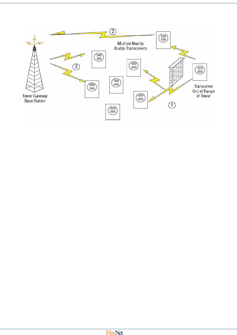
FlexNet SmartPoint Radio Overview A-5
SmartPoint Module for the Elster A3 Meter ECMTM40000
A.3.3.1Buddy Mode Using mPass Transmissions
Figure A-1: Remote SmartPoint to Tower mPass Buddy Mode Schematic
Figure A-1shows how a remote SmartPoint device out-of-range of any tower, an ORD, can send
messages in mPass mode to other Buddy transceivers, which then relay the ORD messages on to
the tower.
1. The out-of-range transceiver (or transmit only device) sends an mPass
modulated message which is received by multiple Buddy transceivers. Each
Buddy queues the message to be repeated with a timeout inversely
proportional to the signal-to-noise ratio (SNR) of the message it received, plus
a small pseudo random amount. Closer Buddy transceivers will have a
shorter timeout.
2. The first Buddy to timeout and repeat the message sends it directly to the
tower on the Normal mode channel. If the tower does not hear the repeated
message, nothing happens until the next Buddy timeout occurs and the next
buddy repeats the message.
3. Once the tower hears a repeated message from a Buddy, it sends an
acknowledge (Ack) message with the ID of the repeated message, which
causes all Buddy devices with a message still queued from that ID to
eliminate that message from their queue. This minimizes the number of times
the message is repeated on air.
A.3.3.2Tower mPass Buddy Mode to ORD Command Transmissions
Figure A-2 exhibits how a remote SmartPoint device that is out-of-range of commands from a
tower can receive those commands via a Buddy relay of the message.
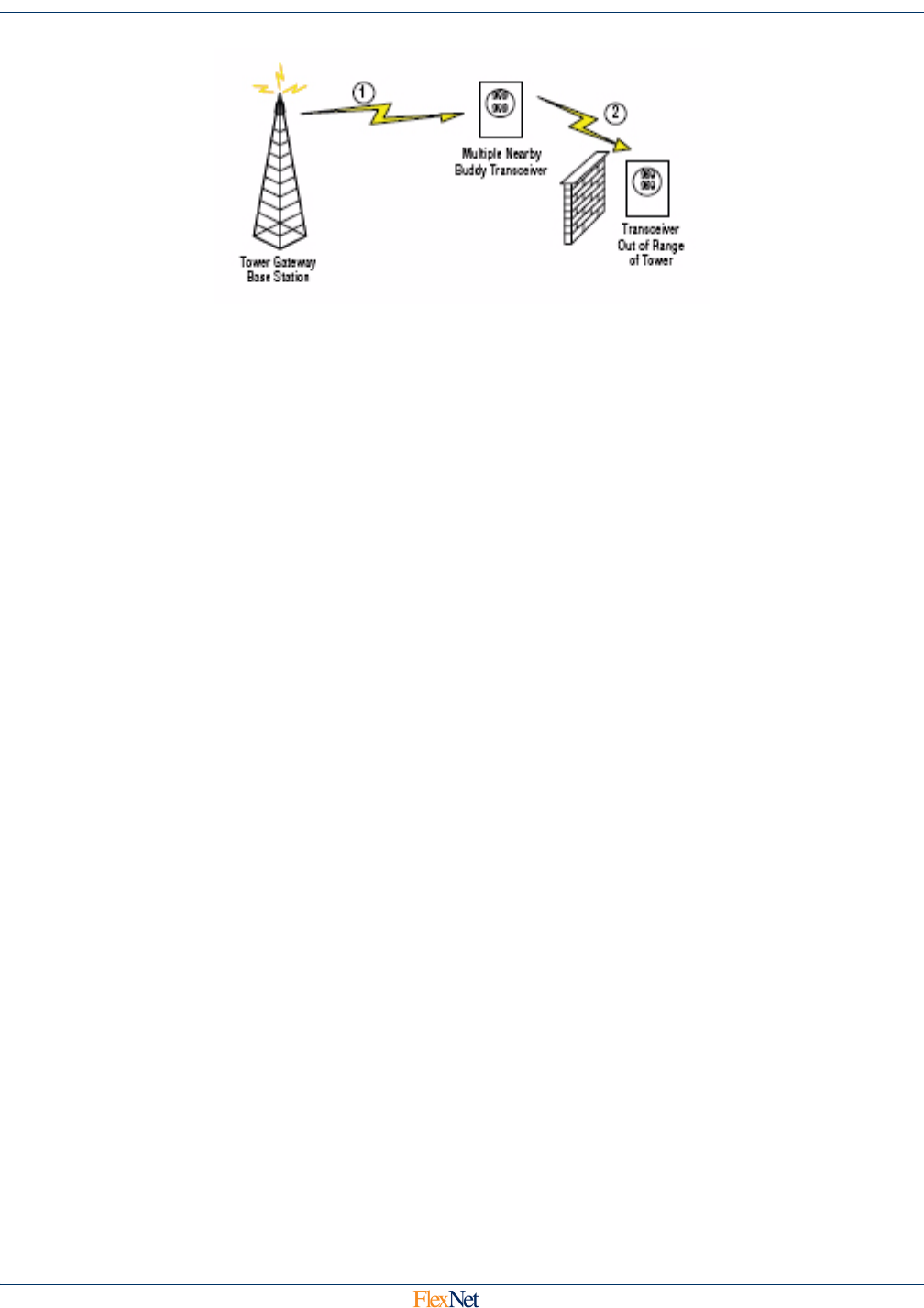
FlexNet SmartPoint Radio Overview A-6
SmartPoint Module for the Elster A3 Meter ECMTM40000
Figure A-2: Remote Tower to SmartPoint mPass Buddy Mode Schematic
1. The tower sends an mPass-modulated message with the address of the out-
of-range transceiver as the primary address, and the address of the desired
relaying Buddy as the Buddy Routing Address. The Buddy receives the
message and identifies it as one the Buddy is commanded to relay.
2. The Buddy transmits the repeated message in the mPass channel to the out-
of-range transceiver.
A.4 SmartPoint Data Security
The FlexNet system is designed with total data security in mind. Sensus is acutely aware that meter reads,
customer data, and telemetry data is highly confidential, and extends every effort to ensure the protection and
integrity of that data. For the protection of customer meter-read data, all meter data can be encrypted at the
meter and remains encrypted throughout the entire communications path until it is inserted into the utility
database, safely inside the utility customer firewall.
A.4.1 SmartPoint Radio Data Security
The SmartPoint radio module is designed to integrate directly into the registers of the host meter.
Register values are read from the meter and encoded into a message inside the SmartPoint radio
module. This message is then mangled in a convolution algorithm, and then encrypted with the system
WEP key, 128 bit, for transmission. In addition, each RF packet is tagged with a sequence number that
allows detection of attempted tampering.
Lastly, the proprietary SmartPoint 7-FSK modulation is not public domain. It is not recognizable by a
spectrum analyzer and no off-the-shelf equipment can be purchased to demodulate it.
A.4.2 TGB Data Security
Once data has arrived at the TGB, additional security measures are added. Data is stored only for the
period of time needed to ensure accurate transmission over the backhaul link to the RNI. Data stored
in the TGB remains encrypted, and the encryption keys are never stored on the same device as the
data.
All communications between the TGB and the RNI occurs over encrypted channels. No data is ever
sent over any network, public or private, in clear text. All backhaul network interactions are conducted
over SSL tunnels using AES-256 encryption.

FlexNet SmartPoint Radio Overview A-7
SmartPoint Module for the Elster A3 Meter ECMTM40000
A.4.3 RNI Data Security
The meter data stream is terminated at the RNI, where it is received via a secure, encrypted tunnel
from the TGB. The actual meter readings are decrypted at this point using the WEP keys, and inserted
into the utility customer-controlled meter-read database.
A.4.4 Separation of Customer Data
Another unique feature of the FlexNet system is the separation of customer data from network
telemetry. This separation, which occurs at the RNI, ensures that customer data is directed to the utility
database, and network telemetry and housekeeping data is directed to the network operations
database. Personal customer data, such as names and street addresses, are never mixed into the
network operations database, ensuring that utilities control the access to information that can
personally identify customers.

Specifications B-1
SmartPoint Module for the Elster A3 Meter ECMTM40000
Appendix B Specifications
B.1 External AC Line Power
•DC Supply A: 13 VDC +/- 1V, 150mA max
•Maximum Message Duration: Supported by supply capacitor, 200 ms
B.2 Current Consumption
The end point device shall have three modes of operation and a different current requirement for each.
•Quiescent Mode: Normal quiescent state. Entered during periods of no input or reading activity to
charge capacitor, microprocessor and local high speed crystal always running. The TCXO and other
peripherals are off in this state. In this state an additional 9 mA is available for charging the transmit
capacitor. ICharge ≤ 6 mA @ the 36 V rectified voltage source.
•Receive Mode: (Optional) A duty cycled state entered to detect if an incoming message is occurring,
and, if so, to receive that message. IReceive ≤ 25 mA @ the 3.3 V supply.
•Pre-Transmit Mode: Before transmission, the uC powers up TCXO, Synthesizer, VCO, and other RF
circuitry before actively transmitting. The current consumption in this mode will be IPre-Transmit ≤ 30
mA @ the 3.3 V supply.
•Transmit Mode: Entered when on air transmission is required. ITransmit ≤ 850 mA @ the 3.6 V
switching regulator.
B.3 Power Failure
•Power Fail Transmission: Following power failure, as detected by a Power Failure IRQ signal from
the iCon display board, the processor shall place the endpoint device into a low power mode until a
programmable time limit up to 120 seconds (Outage Time Threshold). During this time, the device
shall count the number of pulses on the Power Failure IRQ line and keep this information to report in
an Alarm Message to report the outage. Once the Outage Time limit has been reached, the device
shall wait an additional pseudo-random time (up to 152 seconds), at which time it shall transmit an
Alarm Message.
•Power Restored Detection: Once power has been restored (as determined by no Power Fail IRQ
signals being sent by the iCon and the Minimum Voltage Level being exceeded) for longer than the
Power Restored Time Threshold, the device shall wait an additional pseudo-random time (up to 160
seconds) at which time it shall send an Alarm Message indicating Power Restored.

Specifications B-2
SmartPoint Module for the Elster A3 Meter ECMTM40000
B.4 Internal Power Supplies
B.4.1 Micro Power Regulator
Always on, supplies power to CPU, VCO, Buffer Amplifier, Synthesizer, TCXO, and Receiver (if
implemented).
•Drop Out: 60mV @ 50 mA load
•Minimum Voltage Input: 3.4V
•Maximum Voltage Input: 3.8V
•Voltage Output: 3.3V
B.4.2 DC to DC Converter
Enabled during transmit operation.
•Efficiency: 65% Minimum (70% typical)
•Drop Out: 2 V maximum under 850 mA load
•Converter Ripple: ≤ 100mV
•Converter Impulse Response: 750 mA causes ≤ 20 mV spike (TBD)
•Voltage Output: 3.6V +/- 5%
B.5 Start Up Timing Requirements
After changing from Charge Mode to other modes, the device takes the following amounts of time for different
components to be operational.
•DC-DC Converter Stabilization: 10 msec
•TCXO Stabilization: 10 msec
•VCO Frequency Lock: 1.0 msec
•Transmit RF Data: 1.0 msec

Index
SmartPoint Module for the Elster A3 Meter ECMTM40000
Index
A
AC power fail 2
alarm data 18
alarm messages 16
alarms
click count 16
current meter reading 17
data 18
device temperature 17
extended time since event 17
lock errors 17
microprocessor status 17
power failure 1
time of last power failure 18
time since event 16
total number of outages 18
voltage phase 16
App code 1 2, 9
App code 5 3
App code 7 5
App code 8 6
application code 3
application codes
alarm data 18
alarm messages 16
buddy message 6
click count 16
coincident reading 13
command message 5
compression enabled 8
compression enabled history 9
cumulative demand 13
current meter reading 8, 17
data flags/peak demand time 12
delta data type 8
demand history 19, 23
demand reading 13
demand resets 13
device temperature 17
extended time since event 17
last demand reset date & time 20
last peak demand 20
last peak demand reset date & time 20
load profile block data 21
load profile metadata 21
lock errors 17
meter setup/configuration 2
meter type 12
microprocessor status 17
number of demand resets 20
peak demand reading 9
phase voltages 9
quantity of tiers 14
relative time stamp 8
serial number 3
service quality 14
summation reading 13
testing message 1
tier information 11
time of last power failure 18
time since event 16
total # of outages 18
voltage phase alarms 16
application data 3
application fixed bin width history 10
application sequence 3
B
base frequency channel 3
basic command message format 7, 9
basic reply message format 9
battery low 2
boost mode channel 4
brown-out detection 1
buddy id, receiver 9
buddy message 6
C
C&I demand reset, receiver 11
C&I read c12.19 data 10
C&I table read 15
C&I tablewrite 15
click count 16
coincident reading 13
command acknowledge 2
command message 5
command messages
basic status request 9
C&I table read 15
C&I table write 15
demand reset 16
device static setup 11
ping 13
set A/D calibration 12
set customer id 15
set customer meter number 14
set device id 10
set encryption key 12
set installed latitude/longitude 12

Index
SmartPoint Module for the Elster A3 Meter ECMTM40000
set real time clock 13
set TCXO correction 12
set voltage quality threshold 12
command types, receiver 1
company meter number 9
component descriptions 1
compression enabled 8
compression enabled history 9
configurable parameters 1
base frequency channel 3
boost mode channel 4
enable encryption 6
endpoint id 1
meter sample rate 2
programmer id 6
receive frequency channel 4
receiver operational mode 5
supervisory transmit rate 2
transmit channel mask 4
transmit frequency channels 3
transmit operational mode 5
configuration interface
magnetic loop 1
optical direct serial connection 1
control 2
CRC 3
cumulative demand 13
current consumption 1
current meter reading 8, 17
customer id, receiver commands 8
D
data flags 12
data security 6
DC to DC converter 2
delta data type 8
demand history 19, 23
last demand 20
last demand reset date & time 20
last peak demand reset date & time 20
number of demand resets 20
demand reading 13
demand reset 16, 11
demand resets 13
demand, peak 9
description
register display board 1
detection, brown-out 1
device static setup 11
device temperature 17
diversity 1
E
encryption key 8
endpoint id 1
endpoint id parameter 6
external AC line power 1
F
FCC label 1
FCC Part 24 2
fixed bin width history 10
FlexNet module
overview 1
FlexNet network
local network 2
regional network interface 3
SmartPoint module 2
Tower Gateway Base Station 3
FlexNet System
initialization 1
FlexNet system
description 1
frequencies 2
FCC Part 24 2
rss 134 2
H
hazardous voltages 1
I
ID number 1
initialization. SmartPoint 1
internal power supplies 2
L
labels
FCC label 1
labels and hardware 1
last demand reset date & time 20
last peak demand 20
last peak demand reset date & time 20
latitude and longitude 4
length, message 2
load profile block data 21
load profile metadata 21
lock errors 17
M
magnetic loop configuration interface 1
message format
on air 1
message leader 1
meter reading, current 8
meter sample rate 2
meter setup/configuration 2
meter type 12
microprocessor status 17

Index
SmartPoint Module for the Elster A3 Meter ECMTM40000
mPass mode 3
N
narrow-band PCS 2
normal mode 3
notification, power restoral 1
number of demand resets 20
O
on air
time requirements 3
on air control fields
AC power fail 2
battery low 2
payload encrypted 2
power restore 2
RF sequence number 2
on air fields
application code 3
application data 3
application sequence 3
control 2
CRC 3
ID number 1
length 2
message leader 1
repeat level/status 3
sync 1
on air message format 1
on demand read 5
operating frequencies 1
operation modes 1
optical direct serial connection 1
overview
Flexnet module 1
SmartPoint 1
P
payload encrypted 2
PCS frequencies 2
peak demand reading 9
peak demand time 12
phase voltages 9
ping 13
ping, receiver 6
poll-response mode 3
power fail detection 1
power failure 1
power failure alarm 1
power restoral notification 1
power restore 2
preferred buddy id 9
programmer id 6
purpose, manual 1
Q
quantity of tiers 14
R
radio data security 6
receive frequency channel 4
receiver command messages 1
C&I demand reset 11
C&I read c12.19 data 10
C&I writer c12.19 data 10
command acknowledge 2
command types 1
on-demand read 5
ping 6
set company meter number 9
set customer id 8
set encryption key 8
set latitude and longitude 4
set preferred buddy id 9
set static setup 3
set TCXO correction 3
set time 5
set voltage quality settings 4
settransmitter id 7
receiver miscellaneous 11
receiver operational mode 5
receiver polling 11
receiver requirements 1
diversity 1
operation modes 1
RF link requirements 1
sensitivity 1
regional network interface 3
register display board
description 1
relative time stamp 8
repeate level/status 3
requirements, on air time 3
RF link requirements 1
RF sequence number 2
RNI data security 7
RSS 134 2
S
safety 1
security
data 6
radio security 6
RNI data 7
TGB data 6
send data commands 16
sensitivity 1
serial number 3

Index
SmartPoint Module for the Elster A3 Meter ECMTM40000
service quality 14
set A/D calibration 12
set company meter number 9
set customer id 15
set customer meter number 14
set device id 10
set encryption key 12
set encryption key, receiver 8
set installed latitude/longitude 12
set latitude and longitude 4
set preffered buddy id, receiver 9
set real time clock 13
set static setup 3
set TCXO correction 12
set TCXO correction, receiver 3
set time 5
set transmitter id 7
set voltage quality settings 4
set voltage quality threshold 12
setup messages 6
basic command message format 7
basic reply message format 9
command/reply message definitions 9
SmartPoint
brown-out detection 1
Canadian narrow-band PCS 2
data security 6
initialization 1
mPass mode 3
normal mode 3
operating frequencies 1
overview 1
poll-response mode 3
power fail detection 1
power restoral notification 1
radio data security 6
radio transmit modes 2
RNI data security 7
TGB data security 6
U.S. narrow-band PCS 2
SmartPoint frequencies
FCC Part 24 2
RSS 134 2
SmartPoint module 2
SmartPoint power failure detection 1
SmartPoint radio transmit modes 2
specifications 1
current consumption 1
DC to DC converter 2
external AC line power 1
internal power supplies 2
power failure 1
startup timing 2
startup timing 2
status request 9
summation reading 13
supervisory transmit rate 2
sync 1
T
temperature, device alarm 17
testing message 1
TGB data security 6
tier information 11
time of last power failure 18
time since event 16
time since event, extended 17
total # of outages 18
Tower Gateway Base Station 3
transmit channel mask 4
transmit frequency channels 3
transmit modes 2
transmit operational mode 5
transmitter id, receiver commands 7
V
voltage phase alarms 16
voltage quality settings 4
W
write c12.19 data 10