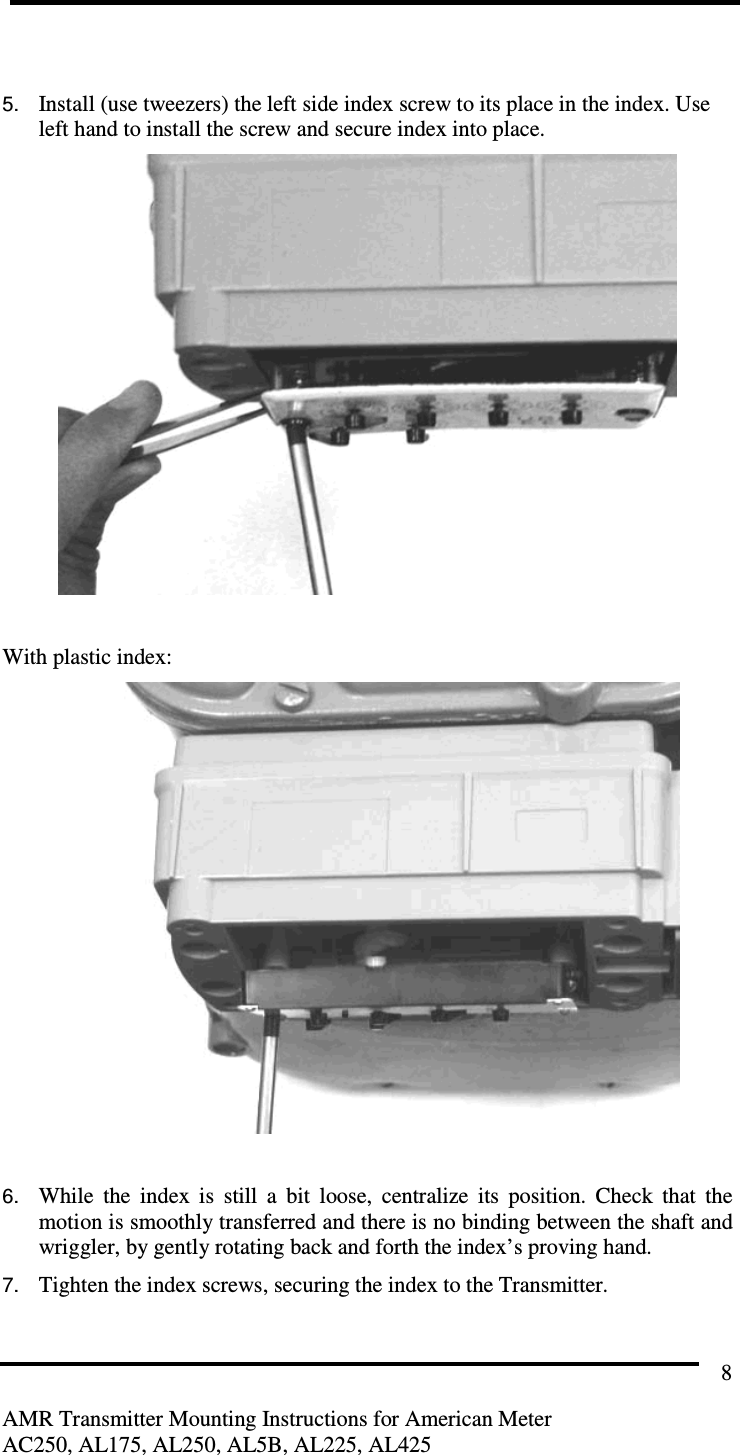
Sensus Metering Systems GS0001 AUTOMATIC GAS METER TRANSMITTER User Manual AC250 TX IS5
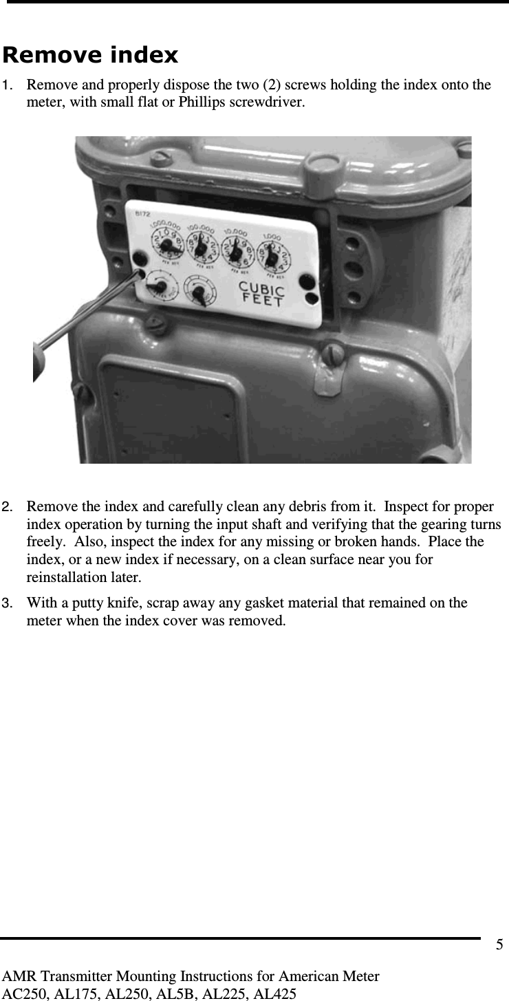
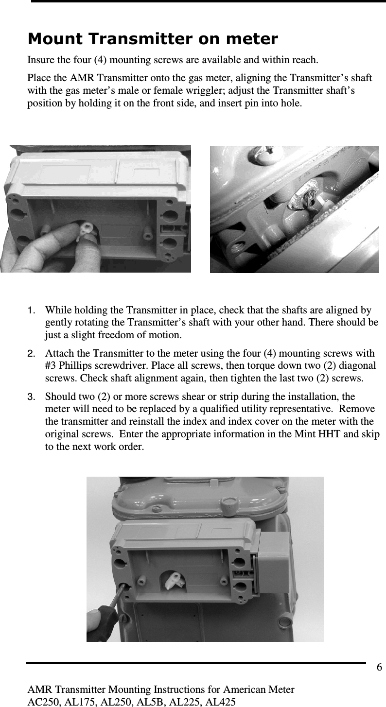
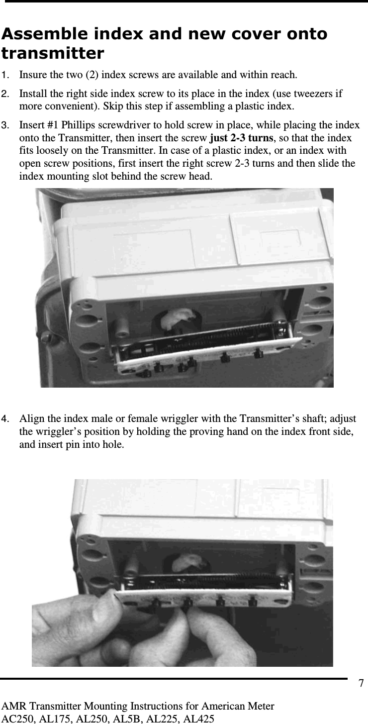
Sensus Metering Systems AUTOMATIC GAS METER TRANSMITTER AC250 TX IS5
UserManual.wiki
>
Sensus Metering Systems
>
GS0001 User Manual
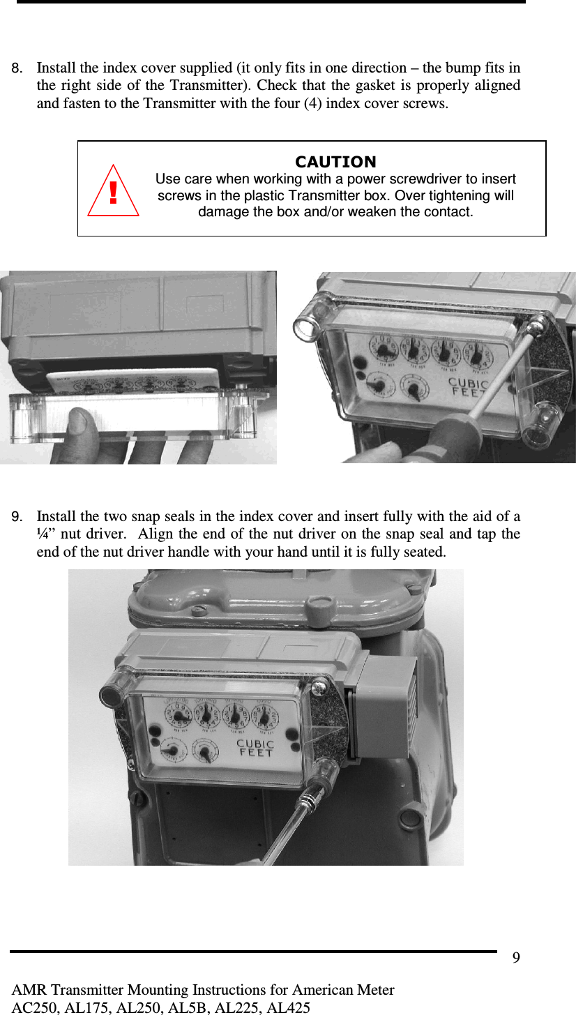
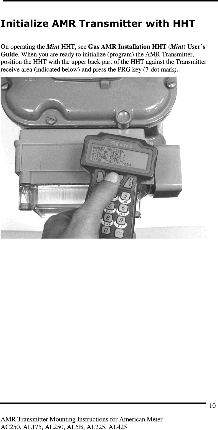
USERS MANUAL
Navigation menu
Upload a User Manual
Namespaces
Wiki Guide
HTML
PDF
Info
Views
User Manual
Discussion / Help
Navigation