Sensus Metering Systems GS0001 AUTOMATIC GAS METER TRANSMITTER User Manual AC250 TX IS5
Sensus Metering Systems AUTOMATIC GAS METER TRANSMITTER AC250 TX IS5
USERS MANUAL

AMR Transmitter Mounting Instructions for American Meter
AC250, AL175, AL250, AL5B, AL225, AL425
1
Automated Meter Reading (AMR)
Transmitter Mounting Instructions
For American Gas Meters
Applicable Meters
AC250, AL175, AL250, AL5B (=AL225), AL425 and any other American Meter model with a
standard residential index.
RF Exposure Note
In order to comply with FCC RF Exposure requirements, the Automatic Meter
Reading unit must be installed in such a way that there is a 20c”m separation
distance between it and all persons during normal operation.
The installer of this radio equipment must ensure that the antenna is located or
pointed such that it does not emit RF field in excess of Health Canada limits for
the general population; consult Safety code 6, obtainable from Health Canada's
website www.hc-sc.gc.ca/rpb
NOTE: THE MANUFACTURER IS NOT RESPONSIBLE FOR ANY RADIO OR TV
INTERFERENCE CAUSED BY UNAUTHORIZED MODIFICATIONS TO THIS EQUIPMENT.
SUCH MODIFICATIONS COULD VOID THE USER’S AUTHORITY TO OPERATE THE
EQUIPMENT
AMR Transmitter Mounting Instructions for American Meter
AC250, AL175, AL250, AL5B, AL225, AL425
2
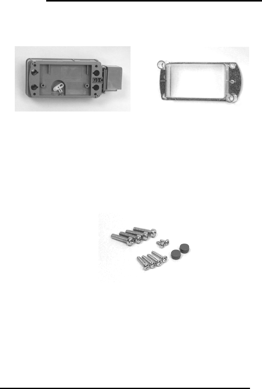
Components
Verify that all the required components for the installation are available:
GS0001 AMR Transmitter Index cover (supplied with the transmitter)
Hardware
Screw kit (see Appendix – Transmitter Installation Screws as identification
guide):
4x mounting screws (thread length 1”)
2x index screws (thread length ⅜”)
4x index cover screws (thread length ¾”)
2x snap seals
Tools
Verify that all the required tools for the installation are available:
#1 Phillips screwdriver
Flat screwdriver (blade size ¼”)
Small flat screwdriver (blade size 5/32”)
Stiff blade putty knife
Pointed tweezers (required for index screw placement)
¼” Nut driver

AMR Transmitter Mounting Instructions for American Meter
AC250, AL175, AL250, AL5B, AL225, AL425
3
Mint handheld terminal (HHT)
AMR Transmitter Mounting Instructions for American Meter
AC250, AL175, AL250, AL5B, AL225, AL425
4
AMR Transmitter Installation
Installation Tasks
1. Remove index cover.
2. Remove index from gas meter.
3. Mount AMR transmitter onto gas meter.
4. Assemble index and cover onto AMR transmitter.
5. Initialize AMR transmitter with HHT.
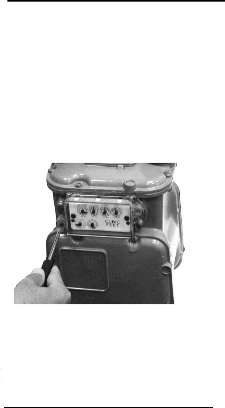
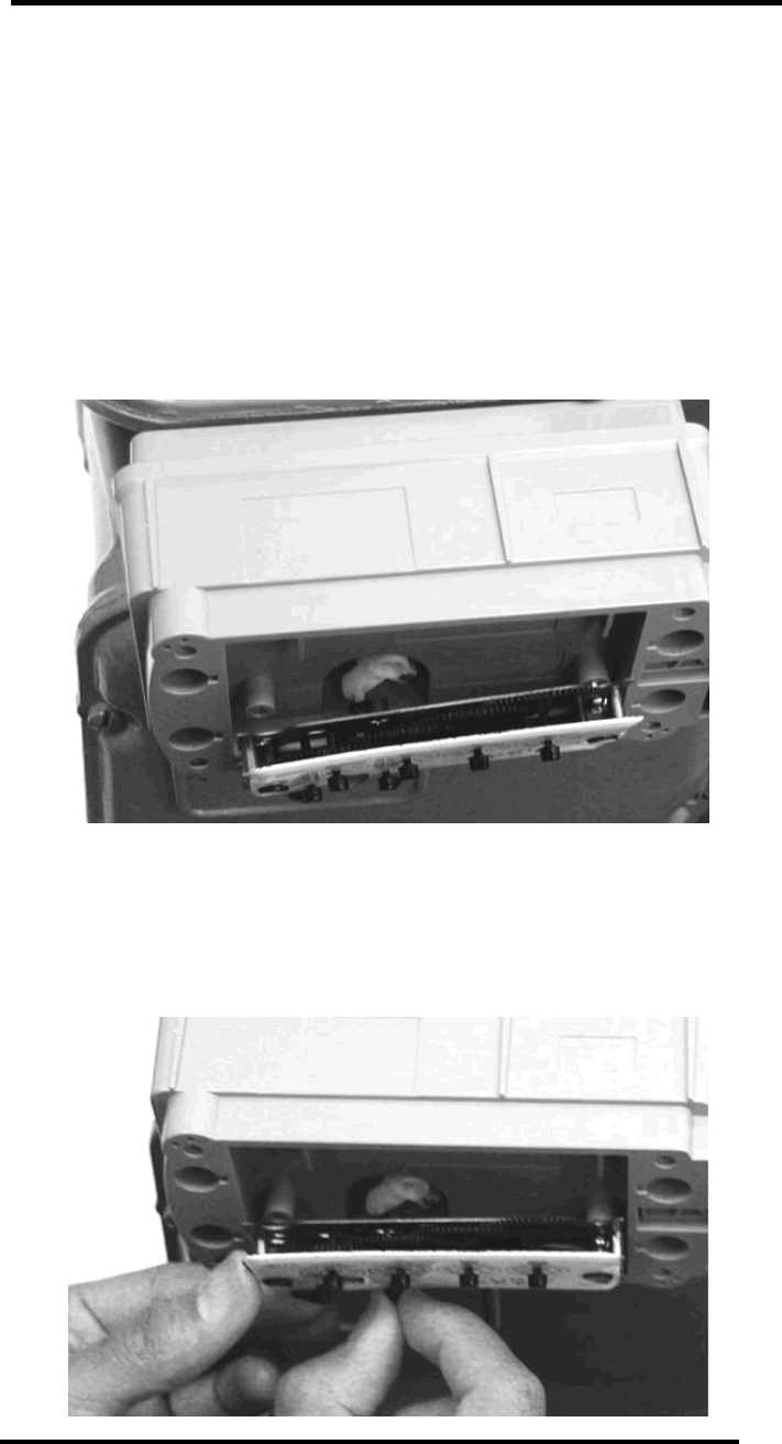
Remove index cover
1. Use small flat screwdriver to punch out the seals that cover two (2) of the
four (4) index cover screws.
2. Remove and properly dispose the four (4) screws holding the index cover
onto meter, with flat screwdriver. If two (2) or more screws shear off during
the cover removal (or were previously sheared off), the meter will need to be
replaced by a qualified utility representative. Reinstall any index cover
screws that were removed and cap with seals if possible. Enter the
appropriate information in the Mint HHT and skip to the next work order.
3. Remove the index cover and dispose of properly.
AMR Transmitter Mounting Instructions for American Meter
AC250, AL175, AL250, AL5B, AL225, AL425
5
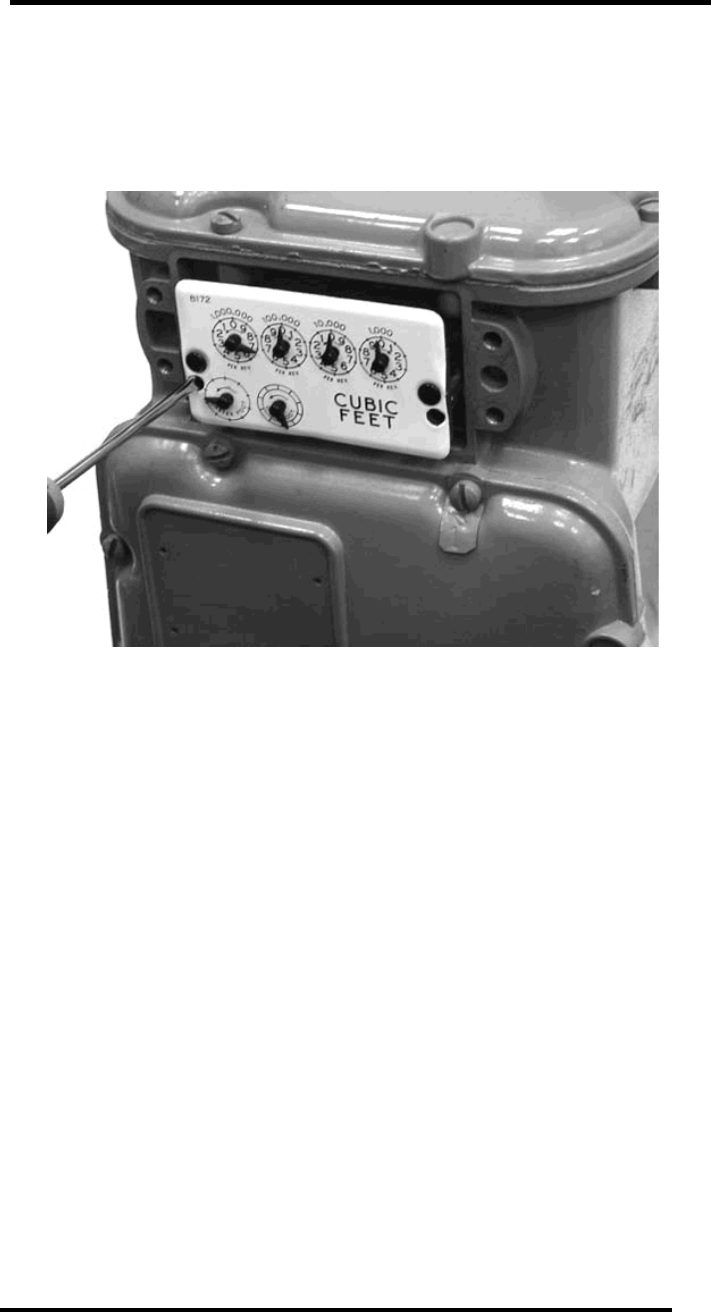
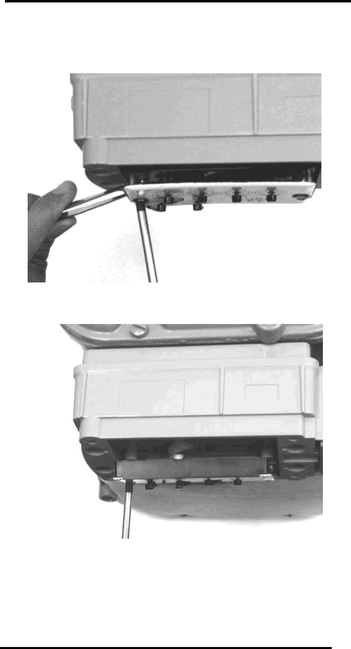
Remove index
1.
Remove and properly dispose the two (2) screws holding the index onto the
meter, with small flat or Phillips screwdriver.
2.
Remove the index and carefully clean any debris from it. Inspect for proper
index operation by turning the input shaft and verifying that the gearing turns
freely. Also, inspect the index for any missing or broken hands. Place the
index, or a new index if necessary, on a clean surface near you for
reinstallation later.
3.
With a putty knife, scrap away any gasket material that remained on the
meter when the index cover was removed.
AMR Transmitter Mounting Instructions for American Meter
AC250, AL175, AL250, AL5B, AL225, AL425
6
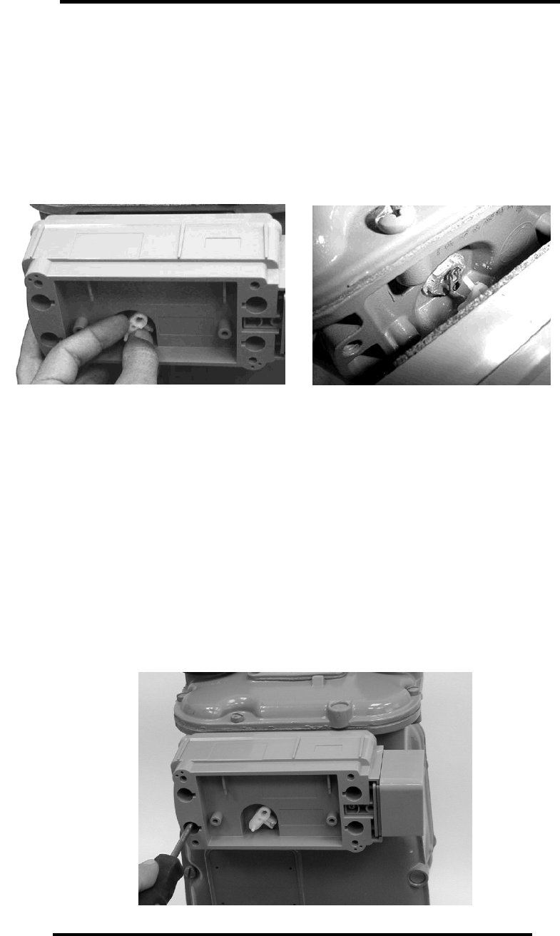
Mount Transmitter on meter
Insure the four (4) mounting screws are available and within reach.
Place the AMR Transmitter onto the gas meter, aligning the Transmitter’s shaft
with the gas meter’s male or female wriggler; adjust the Transmitter shaft’s
position by holding it on the front side, and insert pin into hole.
1.
While holding the Transmitter in place, check that the shafts are aligned by
gently rotating the Transmitter’s shaft with your other hand. There should be
just a slight freedom of motion.
2.
Attach the Transmitter to the meter using the four (4) mounting screws with
#3 Phillips screwdriver. Place all screws, then torque down two (2) diagonal
screws. Check shaft alignment again, then tighten the last two (2) screws.
3.
Should two (2) or more screws shear or strip during the installation, the
meter will need to be replaced by a qualified utility representative. Remove
the transmitter and reinstall the index and index cover on the meter with the
original screws. Enter the appropriate information in the Mint HHT and skip
to the next work order.
AMR Transmitter Mounting Instructions for American Meter
AC250, AL175, AL250, AL5B, AL225, AL425
7
Assemble index and new cover onto
transmitter
1.
Insure the two (2) index screws are available and within reach.
2.
Install the right side index screw to its place in the index (use tweezers if
more convenient). Skip this step if assembling a plastic index.
3.
Insert #1 Phillips screwdriver to hold screw in place, while placing the index
onto the Transmitter, then insert the screw just 2-3 turns, so that the index
fits loosely on the Transmitter. In case of a plastic index, or an index with
open screw positions, first insert the right screw 2-3 turns and then slide the
index mounting slot behind the screw head.
4.
Align the index male or female wriggler with the Transmitter’s shaft; adjust
the wriggler’s position by holding the proving hand on the index front side,
and insert pin into hole.
AMR Transmitter Mounting Instructions for American Meter
AC250, AL175, AL250, AL5B, AL225, AL425
8
5.
Install (use tweezers) the left side index screw to its place in the index. Use
left hand to install the screw and secure index into place.
With plastic index:
6.
While the index is still a bit loose, centralize its position. Check that the
motion is smoothly transferred and there is no binding between the shaft and
wriggler, by gently rotating back and forth the index’s proving hand.
7.
Tighten the index screws, securing the index to the Transmitter.
AMR Transmitter Mounting Instructions for American Meter
AC250, AL175, AL250, AL5B, AL225, AL425
9
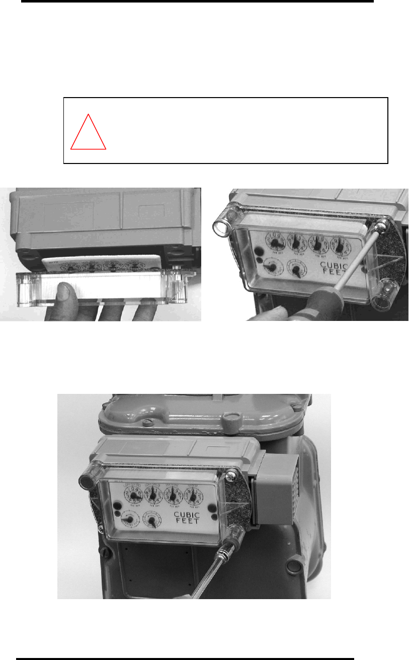
8.
Install the index cover supplied (it only fits in one direction – the bump fits in
the right side of the Transmitter). Check that the gasket is properly aligned
and fasten to the Transmitter with the four (4) index cover screws.
CAUTION
Use care when working with a power screwdriver to insert
screws in the plastic Transmitter box. Over tightening will
damage the box and/or weaken the contact.
9.
Install the two snap seals in the index cover and insert fully with the aid of a
¼” nut driver. Align the end of the nut driver on the snap seal and tap the
end of the nut driver handle with your hand until it is fully seated.
!
AMR Transmitter Mounting Instructions for American Meter
AC250, AL175, AL250, AL5B, AL225, AL425
10
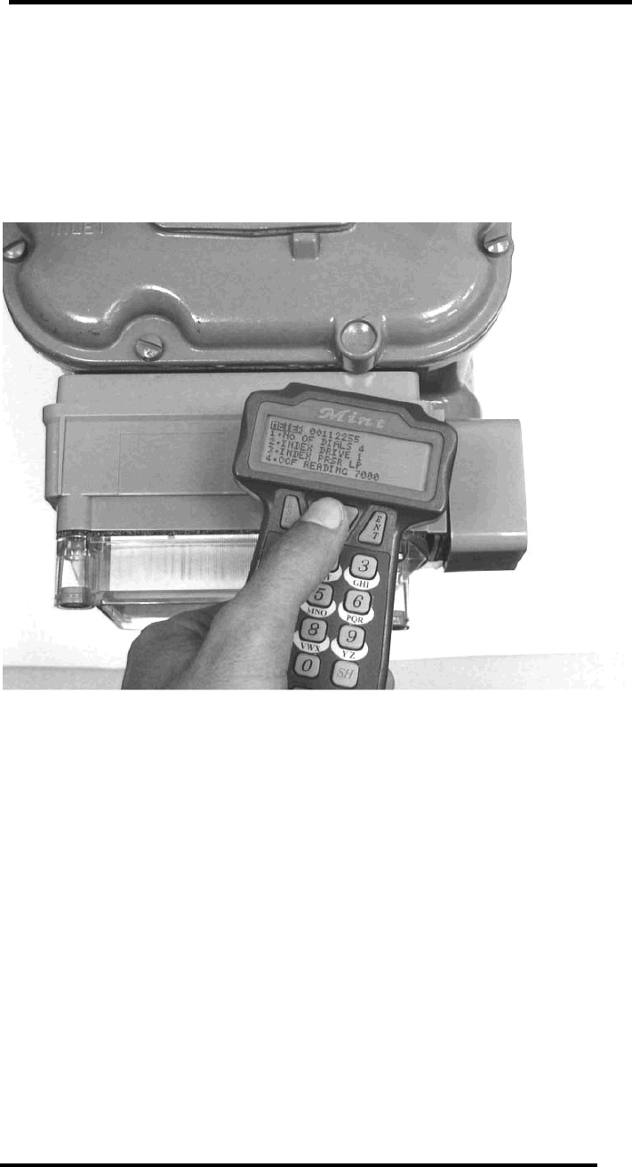
Initialize AMR Transmitter with HHT
On operating the Mint HHT, see Gas AMR Installation HHT (Mint) User’s
Guide. When you are ready to initialize (program) the AMR Transmitter,
position the HHT with the upper back part of the HHT against the Transmitter
receive area (indicated below) and press the PRG key (7-dot mark).
AMR Transmitter Mounting Instructions for American Meter
AC250, AL175, AL250, AL5B, AL225, AL425
11
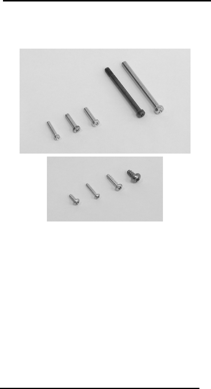
Appendix – Transmitter
Installation Screws
Mounting Screws
1. Equimeter/Rockwell commercial meter (e.g. R750)
– 5/16” x 3½” combo
fillister
2. American commercial meter (e.g. AL800)
– #18-18 x 84 Phillips pan head
3. American residential meter (e.g. AC250)
– ¼” x 1” Phillips fillister
4. Schlumberger/Sprague residential meter (e.g. S175)
– 10-24 x 1” Phillips fillister
5. Equimeter/Rockwell residential meter (e.g. R275)
– 10-24 x 1” Phillips fillister
Index Screws
6. Equimeter/Rockwell commercial meter (e.g. R750)
– WN1411 KA 60x14 Phillips
8. Equimeter/Rockwell residential meter (e.g. R275)
– WN1412 KA 35x22 Phillips
9. American & Schlumberger/Sprague residential meter
– WN1411 KA 40x12 Phillips
Index Cover Screws
7. All residential meters – WN1412 KA 50x20 Phillips
1
2
3
4
5
6
7
8
9