Sensus Metering Systems MXU530T Radio Transceiver for Electric Meter User Manual Technical Manual
Sensus Metering Systems Radio Transceiver for Electric Meter Technical Manual
UserManual.wiki
>
Sensus Metering Systems
>
MXU530T User Manual
Users Manual
Navigation menu
Upload a User Manual
Namespaces
Wiki Guide
HTML
PDF
Info
Views
User Manual
Discussion / Help
Navigation

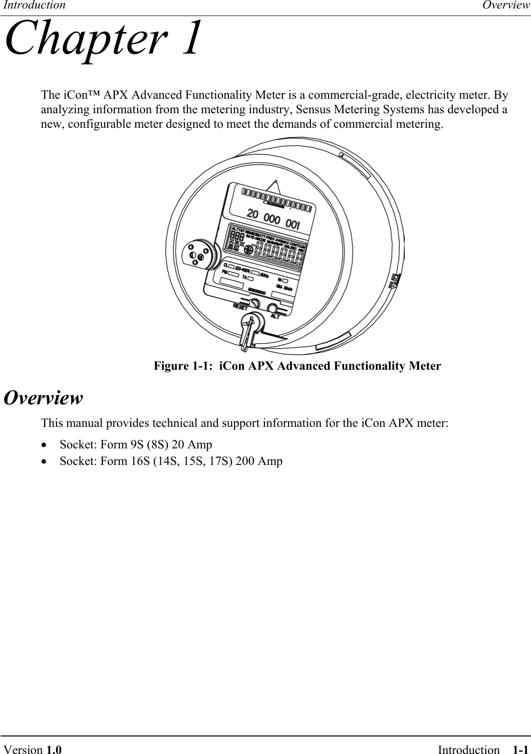
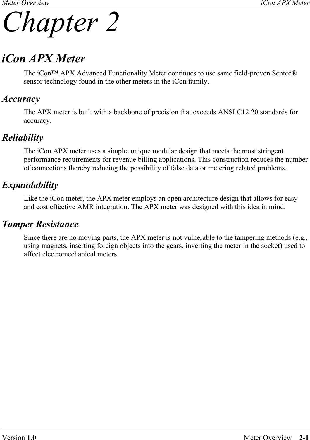
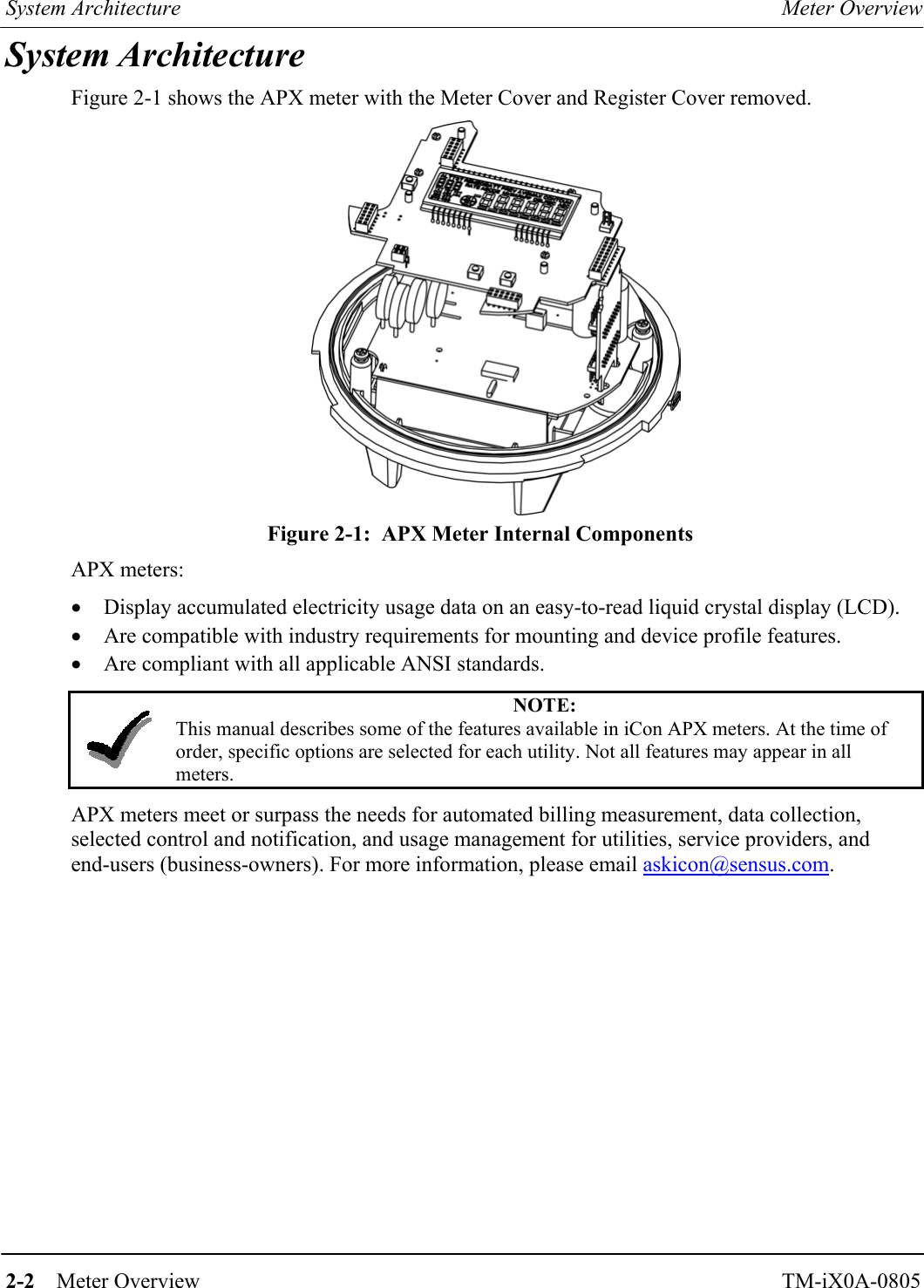
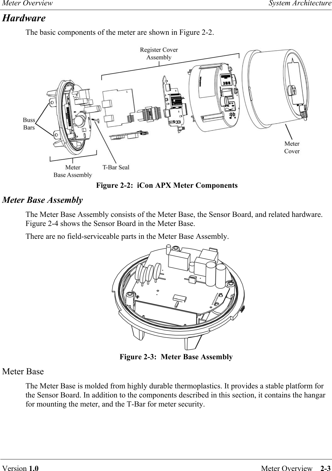
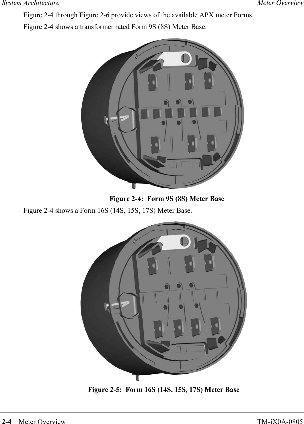
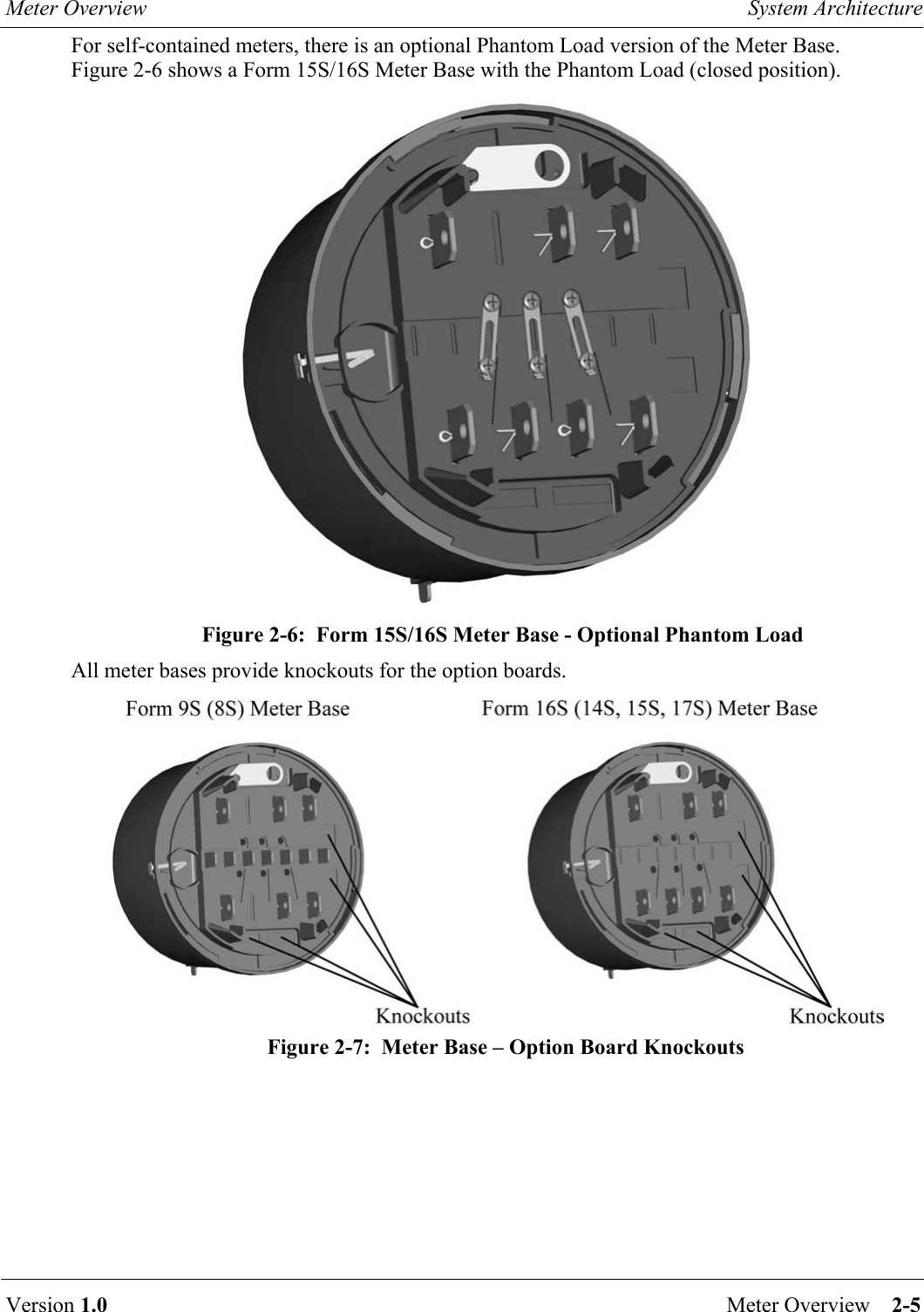
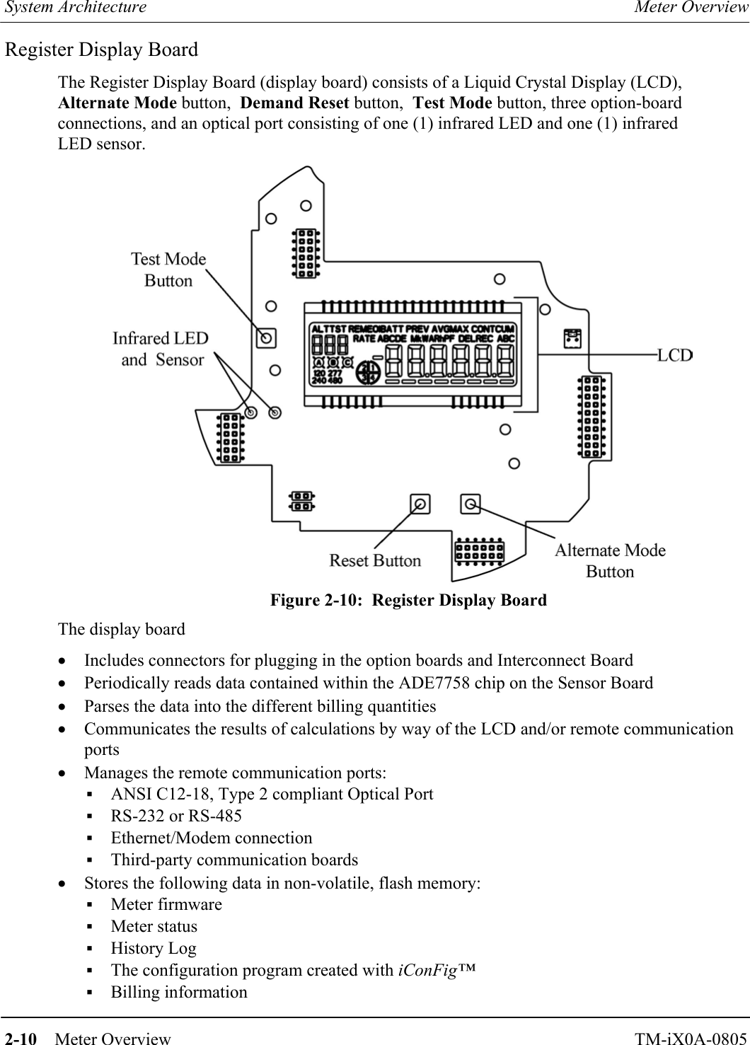
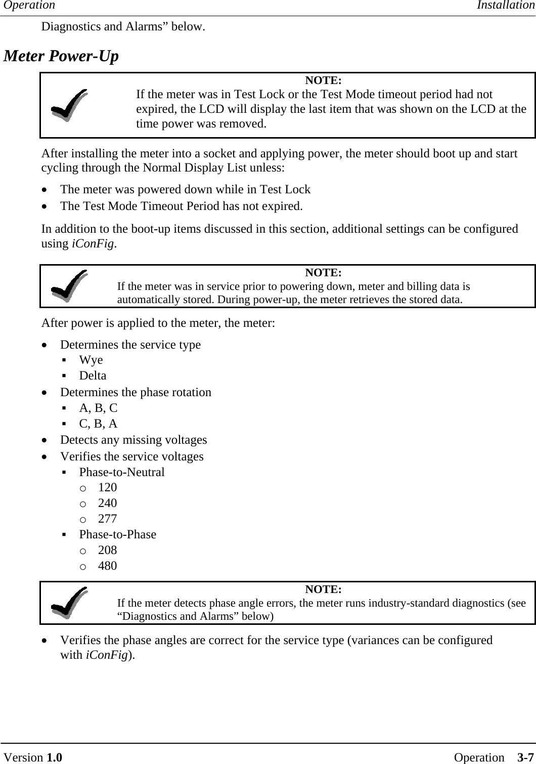
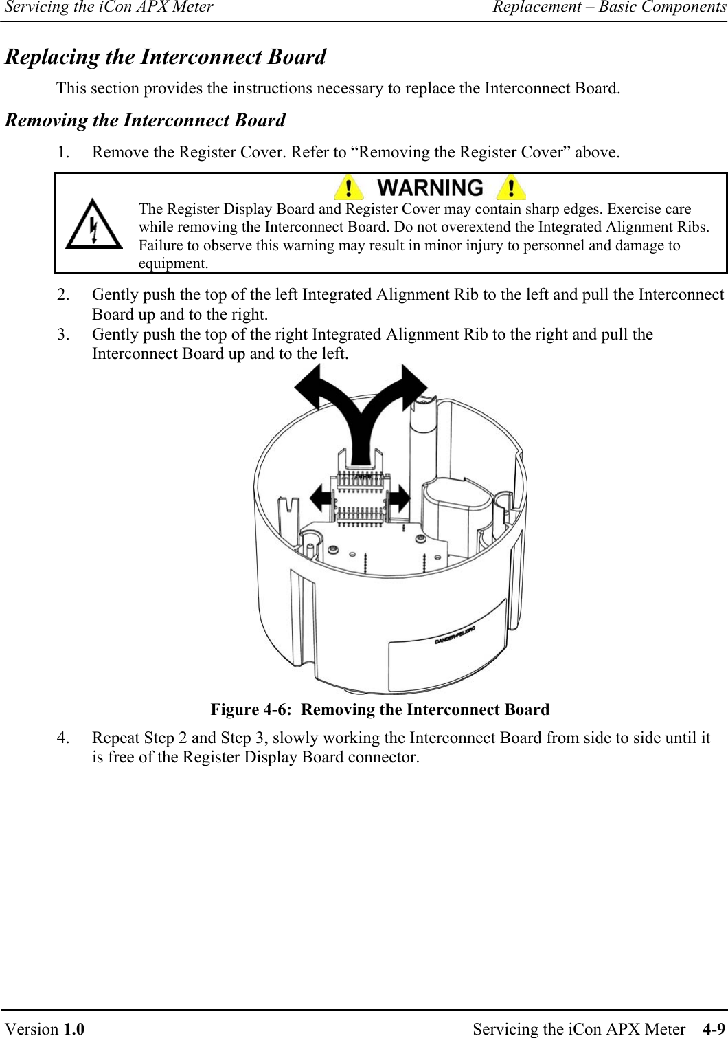
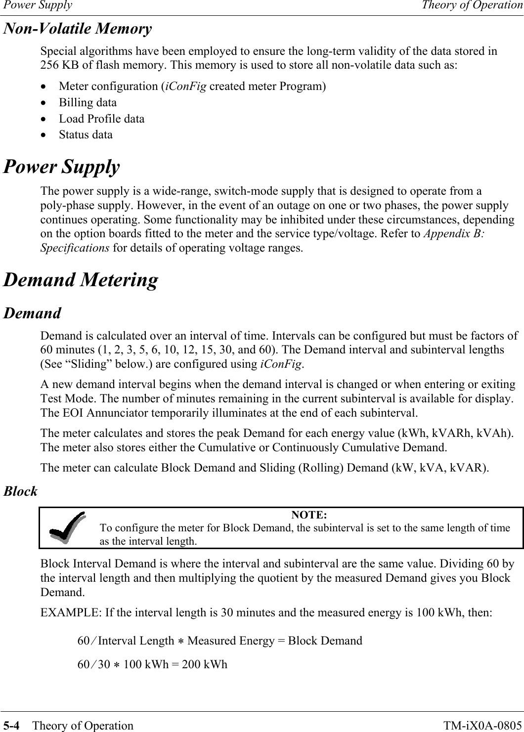
![Installation Operation 3-6 Operation TM-iX0A-0805 Test Mode Operation While the meter is in Display Mode, the Test Pulse correlates to the energy value that is visible on the LCD. NOTE: If the Display List item does not have an energy reading, the Test Pulse will correlate to the kWh present at the meter. Example: If the item on the Display List is kWh delivered, the Test Pulse will correspond to the kWh presently going through the meter. When you press and release the ALT button and the next item on the Display List is kVAR hours, the Test Pulse will correspond to the kVAR hours. The Test Pulse constant (Kt) in Test Mode can be different than the constant (Kh) that is used in Normal, Alternate, and Site Diagnostic Modes. Test Lock To put the meter into Test Lock from Normal Mode, press and hold the TEST button [approximately three (3) seconds] until the TST Annunciator flashes. While in Test Lock, the TST Annunciator will flash. In Test Lock the meter remains in Test Mode for the amount of time configured in the Test Mode Timeout period, even if power is cycled during that time. If the Test Mode Timeout period is set to zero (0), the meter will remain in Test Lock indefinitely. Regardless of whether the meter is in Test Mode or Test Lock, pressing the Test button a second time causes the meter to revert back to Normal Mode. When exiting Test Mode, all previously stored customer-billing data from the “snapshot” is restored to the billing registers and the meter returns to Normal Mode. Reset Button It is possible to reset the energy and Demand values in the Test Mode registers without having to cycle the meter through different modes. While in Test Mode, press and release the RESET button to reset the Test Mode registers. Installation The APX meter is designed to be compatible with the mechanical form factor of existing electromechanical, commercial meters. This design allows technicians and trained meter personnel to perform meter installations easily and without the use of specialized tools. To install the meter, follow the procedures established by your company for standard commercial meters. Should the meter be configured to monitor for diagnostic errors, it may be necessary for the technician to observe the meter for several minutes to ensure no error messages appear. Refer to “](https://usermanual.wiki/Sensus-Metering-Systems/MXU530T/User-Guide-696762-Page-35.png)